R9G-0034-3340AbioCor Implantable Controller
ABIOMED Inc.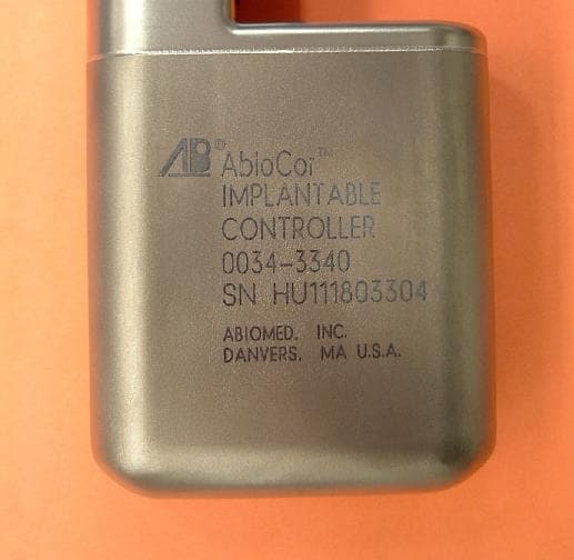
Click to zoom
Application Details
- Equipment Class
- DXT - Part 15 Low Power Transceiver, Rx Verified
- Date of Grant
- Oct 12, 2004
- Application Purpose
- Original Equipment
- Date of Application
- Jul 21, 2004
- Equipment Note
- AbioCor Implantable Controller
- Frequency Range
- 916.50000000 - 916.50000000
- Company
- ABIOMED Inc.
- Country
- United States
Documents & Files
Document Text
Text extracted from the exhibit documents filed with the FCC. Open a document above to read the original.
Users Manual
AbioCor Handheld Monitor INSTRUCTIONS FOR USE ® ® CAUTION: IMPORTANT NOTICE: Read the entire Instructions for Use before using the Handheld Monitor. The Handheld Monitor is to be used only in accordance with the Instructions for Use. Manufactured by: ABIOMED, Inc. 22 Cherry Hill Drive Danvers, MA 01923 USA N. America: 800-422-8666 (24-Hour Emergency Hotline) or 978-777-5410 Document No. 0034-0980-00006 Rev. A DRAFT July 2004 © 2004 ABIOMED, Inc. All rights reserved. Information contained in this document is subject to change without notice. ABIOMED, AbioCor, and the ABIOMED logo are registered U.S. trademarks of ABIOMED, Inc. The AbioCor ® Implantable Replacement Heart System is covered by one or more United States Patents and patents pending. Contents Cautions..............................................................................................................1 Overview.............................................................................................................2 Components of the Handheld Monitor................................................................3 Controls and Features........................................................................................5 Resolving Alarms................................................................................................7 Checking AbioCor ® Status................................................................................13 Checking AbioCor ® Settings and Alarm History...............................................15 Charging the Battery.........................................................................................19 Troubleshooting................................................................................................21 Care and Cleaning............................................................................................23 Appendix: Federal Communications Commission (FCC) Notice...................A.1 About This Manual This manual provides the Instructions for Use for the Handheld Monitor used by patients who have received the AbioCor ® Implantable Replacement Heart System. These Instructions for Use are intended to be used by clinicians, caregivers, and AbioCor patients. For more information about the AbioCor System, refer to the AbioCor Implantable Replacement Heart System - Operator’s Manual; the AbioCor Console Alarms - User’s Guide; and the Patient- Carried Electronics [PCE] - Instructions for Use. 1 Cautions NOTE: A caution indicates a situation in which equipment may malfunction, be damaged, or cease to operate. • Do not use the Handheld Monitor close to an operating AbioCor ® Console. The RF signals from the AbioCor Console and the Handheld Monitor will interfere with each other and not allow adjustments to be made to the Implanted System. If RF interference occurs, turn off the Handheld Monitor. • The Handheld Monitor does not use an indicator to display the status of its battery. However, the alarm message “Handheld Battery” is displayed when the battery is low. You should charge the Handheld Monitor battery every night, whether it is used or not. Overview 2 Overview The Handheld Monitor is a Personal Digital Assistant (PDA) that communicates with the AbioCor ® Implanted Controller. This allows you to quickly access important information about the AbioCor without using the Console. You can use the Handheld Monitor to: • Respond to a Heart Alarm on the PCE Module. • Check AbioCor ® status. • Check AbioCor ® settings and alarm history. You cannot make changes to Beat Rate, Motor Speed, or Balance settings using the Handheld Monitor. These changes must be made using the Console. Before using the Handheld Monitor, you must be trained in the operation of the PCE and the Console. 3 Components of the Handheld Monitor • RF Expansion Module – allows the Handheld Monitor to communicate with the Implanted Controller; draws power from the Handheld Monitor’s battery (even when the unit is off). • Handspring ™ Personal Digital Assistant (PDA) – standard PDA used as the interface component of the Handheld Monitor. • Stylus – used to select items on the screen (fingers can also be used). • Charger – plugs into an AC outlet to charge the Handheld Monitor’s battery. Components of the Handheld Monitor 4 RF Expansion Module Charger Handspring ™ PDA Stylus 5 Controls and Features • Life-Threatening Alarm Light – flashes when a life-threatening alarm condition exists; it also flashes briefly when the RF Expansion Module is inserted. • Application Button – used to access the AbioCor ® Settings Screens and Alarm History Screen. • Power Button – turns the Handheld Monitor on and off; the screen automatically turns off (to save power) if the unit has not been used for 2 minutes. • Touch-Sensitive Screen – displays information; responds to the stylus. • Scroll Buttons, Up/Down Arrows, and Scroll Bar – used to move through information on the screen. Controls and Features 6 Life- Threatening Alarm Light Application Button Up/Down Arrows Scroll Buttons Scroll Bar Touch- Sensitive Screen (Not used) Power Button 7 Resolving Alarms 1 The Handheld Monitor’s AbioCor ® Alarms screen allows you to view two types of alarms: active and inactive. • Active alarm – an existing alarm that has not been acknowledged (“silenced”); indicated by a flashing alarm message. • Inactive alarm – an existing alarm that has been acknowledged; becomes active again if it is not resolved within 2 minutes; indicated by a solid (not flashing) alarm message. NOTE: Alarms that have been resolved without action or acknowledgement may be displayed as solid alarm messages. Resolving Alarms 8 2 Alarms are divided into three levels: Life Threatening, Serious, and Advisory. The following message display methods are used to distinguish each level: • Life Threatening – Active: flashes between black text on light background and light text on black background. Inactive: solid light text with black background. • Serious – Active: flashes …
Text truncated - open the document above for the full version.
Cover Letter(s)
ABIOMED , Inc. CHERRY HILL DRIVETEL: 978-777-5410 DANVERS, MASSACHUSETTS 01923FAX: 978-777-5692 U.S.A. June 29, 2004 Federal Communications Commission 445 12 th Street, S.W. Washington, DC 20554 RE:Request for Confidentiality under 47 CFR § 0.457(d) and/or § 0.459 in ABIOMED, Inc.’s Application for Equipment Certification FCC ID: R9G-0034-3340 Dear Sir or Madam: ABIOMED, Inc. hereby requests that the materials and information specified below in ABIOMED, Inc.’s Application of Equipment Certification for the AbioCor Implantable Controller (part number 0034-3340) be withheld from public inspection. This request for confidentiality is made pursuant to 47 CFR §§ 0.457(d) and 0.459. In compliance with the requirements of 47 CFR § 0.459, we provide the following specific information. • 47 CFR § 0.459(a). A copy of this request is attached to and covers all of the material and information to which it applies, which materials and information are physically separate from any materials and information in the application to which the request does not apply. The material and information to be kept confidential include, without limitation: • All Schematics • All Block Diagrams • All Operational and/or Functional Design Descriptions • All Internal Photos (the product is laser sealed and cannot be opened without destroying the product) • 47 CFR § 0.459(b). ABIOMED, Inc. requests that the above material and information be withheld from public inspection for at lease the reasons set forth below. • 47 CFR § 0.459(b)(1). The specific materials and information for which confidential treatment is sought is set forth above. All such materials and information are physically separate from any materials and information in the application to which the request does not apply. A copy of this request is attached to the materials and information covered by this request. • 47 CFR § 0.459(b)(2). This request is made in connection with the above- referenced Application for Equipment Certification, FCC ID: R9G-0034-3340. ABIOMED , Inc. • 47 CFR § 0.459(b)(3). The materials and information to which this request applies contain ABIOMED, Inc. proprietary and confidential information, which information constitutes substantial ABIOMED, Inc. trade secrets. • 47 CFR § 0.459(b)(4). The materials and information to which this request applies do not concern a service. • 47 CFR § 0.459(b)(5). ABIOMED, Inc. has invested extensive resources to produce the product described in the above-referenced application and to develop the trade secret information included in the materials and information covered by this request. Disclosure of those materials and information would reveal ABIOMED, Inc.’s trade secrets and give competitors unfair commercial advantage in developing similar products. • 47 CFR § 0.459(b)(6). ABIOMED, Inc. has maintained the confidentiality of the trade secret information contained in the materials covered by this request by taking the customary measures for protecting proprietary and confidential trade secret information. • 47 CFR § 0.459(b)(7). To the best of ABIOMED, Inc.’s knowledge, the information contained in the materials covered by this request have not been made publicly available and have been disclosed to third parties only subject to non-disclosure agreements. • 47 CFR § 0.458(b)(8). ABIOMED, Inc. requests that the information contained in the materials covered by this request should not be available for public disclosure indefinitely as long as such information remains ABIOMED, Inc. trade secrets or, in the alternative, as long as permitted under the relevant laws and regulations. If additional information or explanation is required to grant this request, please contact the undersigned at 978-646-1478 or [email protected] . Sincerely, Tracy Palmer Berns Regulatory Affairs Manager and Staff Attorney
External Photos
ABIOMED , Inc. 0034-3340 Implantable Controller External Photos 0034-3340 Implantable Controller – Front View ABIOMED , Inc. 0034-3340 Implantable Controller – Side View ABIOMED , Inc. 0034-3340 Implantable Controller – Back View ABIOMED , Inc. 0034-3340 Implantable Controller – With Cable / Antenna Antenna Cable
ID Label/Location Info
B C D A B C D 1 234 4 A 3 2 1 REVISIONS SHEET OF ABIOMED Inc. PROPRIETARY AND PRIVATE The information contained in this document is the property of ABIOMED Inc. and shall be kept in strict confidence. Except with the express written permission of ABIOMED Inc., such information shall not be published or disclosed to others, or used for manufacture, sale or any other purpose, and this document shall not be reproduced, in whole or in part. If written permission is granted for reproduction, this legend shall be included in any such reproduction. This document and all copies of this document, in whole or in part, and with or without modifications shall be returned to ABIOMED Inc. upon request, upon completion of the use for which it was made available to recipient, or termination of relationship with recipient, whichever first occurs. Any recipientAny recipient so atance of this document or item. APPLICATION USED ONNEXT ASSY TAH- REVISION ZONELTRDATEAPPROVED LIST OF PARTS ITEM NO. QTY REQD PART OR IDENTIFYING NO. NOMENCLATURE OR DESCRIPTION MATERIAL UNLESS OTHERWISE SPECIFIED DIMENSIONS ARE IN INCHES. TOLERANCES ARE: DO NOT SCALE DRAWING DECIMALS .X ± .1 ANGLES ± .5° .XX ± .01 .XXX ± .005 .XXXX ± .0005 APPROVALSDATE DRAWN B. SOARES 6-23-04 IMPLANTABLE CONTROLLER WELDMENT/MARKING MATERIAL CHECKED ___ __ ENGR ___ __ FINISHED SURFACES 63 BREAK SHARP CORNERS .005 APPROV ___ __ SIZE C CHERRY HILL DR. DANVERS, MA 01923 (978) 777-5410 DRAWING NO. REV CASE 0034 0034-0966-00236-0X1 DO NOT SCALE DRAWING SCALE NTS 1 1 DANVERS, MA U.S.A. ABIOMED, INC. FCC ID: R9G-0034-3340 SN XXXXXXXXX 0034-3340 CONTROLLER IMPLANTABLE AbioCor R TM
ID Label/Location Info
1.35±.10 TM R ABIOMED Inc. PROPRIETARY AND PRIVATE The information contained in this document is the property of ABIOMED Inc. and shall be kept in strict confidence. Except with the express written permission of ABIOMED Inc., such information shall not be published or disclosed to others, or used for manufacture, sale or any other purpose, and this document shall not be reproduced, in whole or in part. If written permission is granted for reproduction, this legend shall be included in any such reproduction. This document and all copies of this document, in whole or in part, and with or without modifications shall be returned to ABIOMED Inc. upon request, upon completion of the use for which it was made available to recipient, or termination of relationship with recipient, whichever first occurs. Any recipient so agrees by acceptance of this document or item. CHERRY HILL DR.DANVERS,MA 01923(978) 777-5410 MODEL NAME UNLESS OTHERWISE SPECIFIED DIMENSIONS ARE IN INCHES. TOLERANCES ARE: DO NOT SCALE DRAWING DECIMALS .X ± .1 ANGLES ± .5° .XX ± .010 .XXX ± .005 .XXXX ± .0005 APPROVALSDATE DRAWN B. SOARES6/23/04 MATERIAL CHECKED XXX XX LASERMARK, IMPLANTABLE CONTROLLER ------------ ENGR XXX XX FINISHED SURFACES 63 BREAK SHARP CORNERS .010 APPROV XXX XX SIZE A DRAWING NO.REV QA XXX XX 0034-0966-00170-AX1 DO NOT SCALE DRAWING DOC CTRL XXX XX SCALE 2.001 of 1 REVISIONS APPROVED DATE DESCRIPTION LTR AbioCor IMPLANTABLE CONTROLLER 0034-3340 SN XXXXXXXXX FCC ID: R9G-0034-3340 ABIOMED, INC. DANVERS, MA U.S.A.
Test Report
ABIOMED , Inc. 0034-3340 AbioCor Implantable Controller RF Telemetry – RF Exposure The AbioCor Implantable Controller contains the electronic circuitry required to run the AbioCor Implantable Replacement Heart. The Implantable Controller is surgically implanted in the abdomen of an AbioCor Implantable Replacement Heart patient. The RF telemetry transceiver is part of the Implantable Controller. An antenna, which is part of the implantable cable, is attached to the Implantable Controller and located in the patient’s abdomen. The AbioCor Implantable Controller’s RF telemetry system was tested to 47 CFR 15.249. Based on correspondence with the FCC, the Implantable Controller and antenna were submersed in a phantom material that simulates human tissue during the testing. The antenna and Implantable Controller were positioned 2 cm inside the phantom material as recommended by the FCC. Correspondence with the FCC can be found in Attachment 1. The formula for the phantom material and paper referenced in OTE Bulletin 65 Supplement C can be found in Attachment B. ABIOMED , Inc. Attachment 1 Correspondence with the FCC 1 D'Ambrosio, Ralph From: Phyllis Parrish [[email protected]] Sent: Tuesday, March 30, 2004 7:06 AM To: LabHelp Cc: [email protected] Subject: RE: Question Question: The AbioCor implantable telemetry system uses an OOK modulated transceiver operating at 916.5 MHz and is designed to comply with 47 CFR 15.249. Below is some of the information that Richard has requested: The radiated output power of the device is approximately -8.0 dBm (158uW) at the implantable antenna. The transmitted data uses a bit-balancing scheme, similar to Manchester encoding, since the base band signal is AC coupled. The implantable transmitter is active about 90% of the time. During the remaining 10%, the implantable receiver is enabled to accept inbound commands. Below are some facts to ease your concern regarding "Part 15 devices, which have no protection against harmful interference, to be used for life-saving/preserving devices" for this application. 1) The RF telemetry is not required to maintain operation of the device. (example: If the RF link is down for a day there will be no adverse effect) 2) All of the inbound and outbound data use a CRC to maintain data integrity. 3) Commands required to disable the device require multiple messages. 4) The entire AbioCor system will undergo full immunity testing per EN60601-1-2 which include full testing of the EN61000-3 and EN61000-4 families of standards. 5) The AbioCor system has been undergoing clinical trials for the past 2-1/2 years using this telemetry system. Never has interference been interpreted as, or caused desired message to be interpreted as, something other than the intended message. Please let me know if you require any additional information. Your prompt response is appreciated as we would like to commence testing next week. You can reach me in the office at 978-646-1709. If you receive my voice mail, please dial "0" and have the operator page me, or you can try my cell phone at 978-314-6517. Best Regards, Ralph D'Ambrosio [email protected] Answer: We will allow testing in the open air or in a fluid that simulates body tissue on an open area test site. The choice is up to 2 you. ANSI C63.4 requires testing in the open air, however, we have allowed other Part 15 transmitters to be tested in-situ or as-installed. A transmitter tested in air will be placed stand-alone on the tabletop. A transmitter tested in fluid must not be more than 2 cm inside the fluid on the tabletop. Be aware that a device tested in fluid will appear to have more power when compared side-by side to one tested in the open air. This could be advantageous to your future marketing plans. Supplement C to OET Bulletin 65 contains recipes for "phantom materials". 1 D'Ambrosio, Ralph From: LabHelp [[email protected]] Sent: Tuesday, March 16, 2004 8:29 AM To: D'Ambrosio, Ralph Subject: RE: Question We are in receipt of your e-mail dated March 10, 2004. After some research, it appears that we will need additional time to provide an appropriate response to your inquiry. We will therefore be responding to your e-mail within one to two weeks. If you have any questions, please send me an e-mail with your concerns. Hello, I am contacting you at Richard Fabina's direction. Please see the emails below for some background. The AbioCor implantable telemetry system uses an OOK modulated transceiver operating at 916.5 MHz and is designed to comply with 47 CFR 15.249. Below is some of the information that Richard has requested: The radiated output power of the device is approximately -8.0 dBm (158uW) at the implantable antenna. The transmitted data uses a bit-balancing scheme, similar to Manchester encoding, since the base band signal is AC coupled. The implantable transmitter is active about 90% of the time. During the remaining 10%, the implantable receiver is enabled to accept inbound commands. Below are some facts to ease your concern regarding "Part 15 devices, which have no protection against harmful interference, to be used for life-saving/preserving devices" for this application. 1)The RF telemetry is not required to maintain operation of the device. (example: If the RF link is down for a day there will be no adverse effect) 2)All of the inbound and outbound data use a CRC to maintain data integrity. 3)Commands required to disable the device require multiple messages. 4)The entire AbioCor system will undergo full immunity testing per EN60601-1-2 which include full testing of the EN61000-3 and EN61000-4 families of standards. 5)The AbioCor system has been undergoing clinical trials for the past 2-1/2 years using this telemetry system. Never has interference been interpreted as, or caused desired message to be interpreted as, something other than the intended message. Please let me know if you require any additional information. Your prompt response is appreciated …
Text truncated - open the document above for the full version.
Test Report
Emissions Testing Performed on the Abiomed AbioCor TM Implantable Replacement Heart To FCC Part 15, Subpart C, Section 15.249 Date(s) of Test: April 30 and May 21, 2004 Page 1 of 22 Report Number: 3058793 Contact: Mr. Charles Kolifrath All services undertaken are subject to the following general policy: Reports are submitted for exclusive use of the client to whom they are addressed. Their significance is subject to the adequacy and representative character of the samples and to the comprehensiveness of the tests, examinations or surveys made. No quotations from reports or use of Intertek Testing Services NA Inc. name is permitted except as expressly authorized by Intertek Testing Services NA Inc. in writing. This report must not be used to claim product endorsement by NVLAP, NIST or any other agency of the U.S. Government. Intertek Testing Services NA, Inc. Part 15 Laboratory Measurements and ANSI C63.4-2001 Project Number: 3058793 Revision March 24, 2000 Page 2 of 22 This document may not be reproduced except in its entirety without written permission from ITS. Table of Contents TABLE OF CONTENTS........................................................................................................................................................... 2 I – INTRODUCTION AND SUMMARY ................................................................................................................................................. 3 II – TECHNICAL REQUIREMENTS....................................................................................................................................................... 4 15.1 SCOPE......................................................................................................................................................................................... 4 15.15 GENERAL TECHNICAL REQUIREMENTS............................................................................................................................ 4 15.27 SPECIAL ACCESSORIES.......................................................................................................................................................... 4 15.31 MEASUREMENT STANDARDS .............................................................................................................................................. 4 15.33 FREQUENCY RANGE OF MEASUREMENT ......................................................................................................................... 4 15.35 MEASUREMENT DETECTOR FUNCTIONS AND BANDWIDTH ....................................................................................... 4 15.37 TRANSITION PROVISIONS ..................................................................................................................................................... 5 15.105 INFORMATION TO THE USER................................................................................................................................................. 5 15.107 CONDUCTED LIMITS. ............................................................................................................................................................. 6 15.109 RADIATED EMISSION LIMITS. ................................................................................................................................................ 7 15.111 ANTENNA POWER CONDUCTION LIMITS FOR RECEIVERS. ............................................................................................ 8 15.201 CERTIFICATION ....................................................................................................................................................................... 8 15.203 ANTENNA REQUIREMENTS .................................................................................................................................................. 8 15.204 EXTERNAL RADIO AMPLIFIER............................................................................................................................................. 9 15.205 RESTRICTED BANDS OF OPERATION ................................................................................................................................. 9 15.207 CONDUCTED LIMITS .............................................................................................................................................................. 9 15.209 RADIATED EMISSION LIMITS; GENERAL REQUIREMENTS ........................................................................................... 9 15.249 OPERATION WITHIN THE BANDS 902-928MHZ, 2400-2483.5MHZ, 5725-5875, AND 24.0-24.25GHZ ........................ 10 III - ATTESTATION ............................................................................................................................................................................... 11 IV - SITE DESCRIPTION....................................................................................................................................................................... 12 V - MEASUREMENT EQUIPMENT ..................................................................................................................................................... 13 VI - CONFIGURATION INFORMATION............................................................................................................................................. 14 VII - CONFIGURATION PHOTOGRAPHS .......................................................................................................................................... 15 VIII - SAMPLE CALCULATION .......................................................................................................................................................... 17 IX - DATA TABLES ............................................................................................................................................................................... 18 X - DUTY CYCLE (AV…
Text truncated - open the document above for the full version.
Test Report
From: Roland Gubisch ES-Box Sent: Friday, September 17, 2004 4:02 PM To: 'D'Ambrosio, Ralph'; Danielle Fontaine ES-Box Subject: RE: Correspondence reference number 27518 Ralph, Thank you, we have received your e-mail. Danielle will upload the exhibits and these comments early next week. Regards, Roland -----Original Message----- From: D'Ambrosio, Ralph [mailto:[email protected]] Sent: Friday, September 17, 2004 3:57 PM To: Roland Gubisch ES-Box; Danielle Fontaine ES-Box Subject: Correspondence reference number 27518 Importance: High Roland / Danielle, Below is the edited text to upload with the test reports. Please confirm the receipt of this email. Thanks & have a good weekend, Ralph ___________________________________________ Andrew, This email is in response to correspondence reference number 27518. (attached) Below is the response to your letter, in order. 1) The test report for the implantable unit and setup photos have been uploaded; we regret the oversight. 2) The implantable unit contains antenna integrated into the implantable cable assembly, which makes conducted RF power measurement very difficult. Radiated emissions were measured both in air and simulation fluid, and worst-case field strength of the 916.6 MHz fundamental at 3m was: in air: 84.7 dBuV/m in fluid: 64.2 dBuV/m Full details are contained in the test report. If I can be of further assistance, please contact me at [email protected], or 978-314-6517. Sincerely, Ralph D'Ambrosio Abiomed Inc. <<Pending Status via FCC 9-16-04.pdf>> ______________________________________
Test Setup Photos
Worst-Case Radiated Emissions (in simulation fluid) Worst-case conducted emissions (Patient Console only)
Test Setup Photos
Andrew, This email is in response to correspondence reference number 27728. Below is the response to your email, in order. 1. The setup of the of the implantable subsystem inside the container is shown in figures 1 and 2. The RF telemetry transceiver is housed within the Implantable Controller. The antenna is a 15cm wire with a carbothane jacket that exits the implantable controller via a hermetic multipin connector. The antenna was spaced 2cm from the wall of the enclosure as recommended by the FCC per the attached Lab Help Email below. THORACIC UNIT 2 cm IMPLANTABLE CONTROLLER HOSES INTERNAL TET BATTERY CABLE ANTENNA 5 GALLON PLASTIC BUCKET CONTAINING PHANTOM MATERIAL. EXTERNAL TET ALL PLASTIC CONSTRUCTION PHANTOM MATERIAL Figure 1 TRANSCEIVER IMPLANTABLE CONTROLLER CABLE 5 GALLON PLASTIC BUCKET CONTAINING PHANTOM MATERIAL. ALL PLASTIC CONSTRUCTION PHANTOM MATERIAL ANTENNA OTHER IMPLANTABLE ELEMENTS NOT SHOWN Figure 2 From: Phyllis Parrish [[email protected]] Sent: Tuesday, March 30, 2004 7:06 AM To: LabHelp Cc: [email protected] Subject: RE: Question Question: The AbioCor implantable telemetry system uses an OOK modulated transceiver operating at 916.5 MHz and is designed to comply with 47 CFR 15.249. Below is some of the information that Richard has requested: The radiated output power of the device is approximately -8.0 dBm (158uW) at the implantable antenna. The transmitted data uses a bit-balancing scheme, similar to Manchester encoding, since the base band signal is AC coupled. The implantable transmitter is active about 90% of the time. During the remaining 10%, the implantable receiver is enabled to accept inbound commands. Below are some facts to ease your concern regarding "Part 15 devices, which have no protection against harmful interference, to be used for life-saving/preserving devices" for this application. 1) The RF telemetry is not required to maintain operation of the device. (example: If the RF link is down for a day there will be no adverse effect) 2) All of the inbound and outbound data use a CRC to maintain data integrity. 3) Commands required to disable the device require multiple messages. 4) The entire AbioCor system will undergo full immunity testing per EN60601-1-2 which include full testing of the EN61000-3 and EN61000-4 families of standards. 5) The AbioCor system has been undergoing clinical trials for the past 2-1/2 years using this telemetry system. Never has interference been interpreted as, or caused desired message to be interpreted as, something other than the intended message. Please let me know if you require any additional information. Your prompt response is appreciated as we would like to commence testing next week. You can reach me in the office at 978-646-1709. If you receive my voice mail, please dial "0" and have the operator page me, or you can try my cell phone at 978-314-6517. Best Regards, Ralph D'Ambrosio [email protected] Answer: We will allow testing in the ope…
Text truncated - open the document above for the full version.
Contact Information
Applicant
Ralph L D'Ambrosio(Director, Electronic Engineering)
Technical Contact
ABIOMED, Inc.Ralph D'Ambrosio
[email protected]978-646-1709
22 Cherry Hill Drive · Danvers, Massachusetts · United States
Non-Technical Contact
ABIOMED, Inc.Tracy Berns
[email protected]978-646-1478
Test Firm
Intertek Testing Services NA Inc.Roland Gubisch
Technical Specifications
| # | Rule Parts | Frequency Range | Power Output |
|---|---|---|---|
| 1 | 15C | 916.5 MHz - 916.5 MHz | - |
Other Applications from ABIOMED Inc.
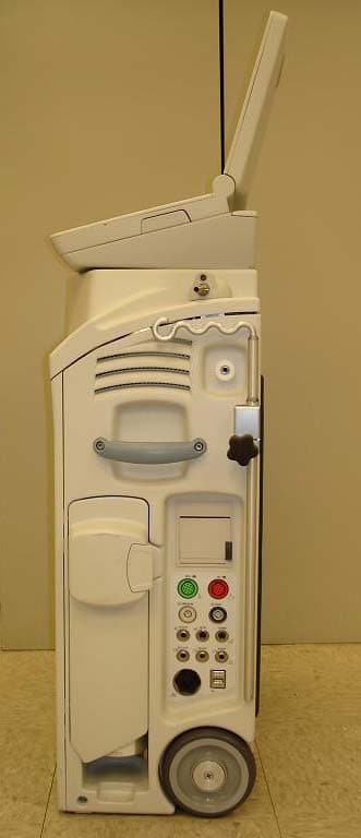
R9G-0036-0010
Nov 19, 2006SupraCor
Equipment Class
FAP - Part 15 Anti-Pilferage Device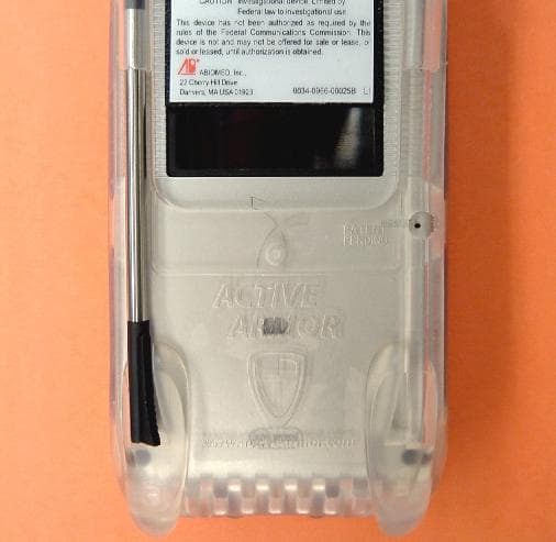
R9G0034-4590
Nov 01, 2004AbioCor HandHeld Monitor
Equipment Class
DXT - Part 15 Low Power Transceiver, Rx Verified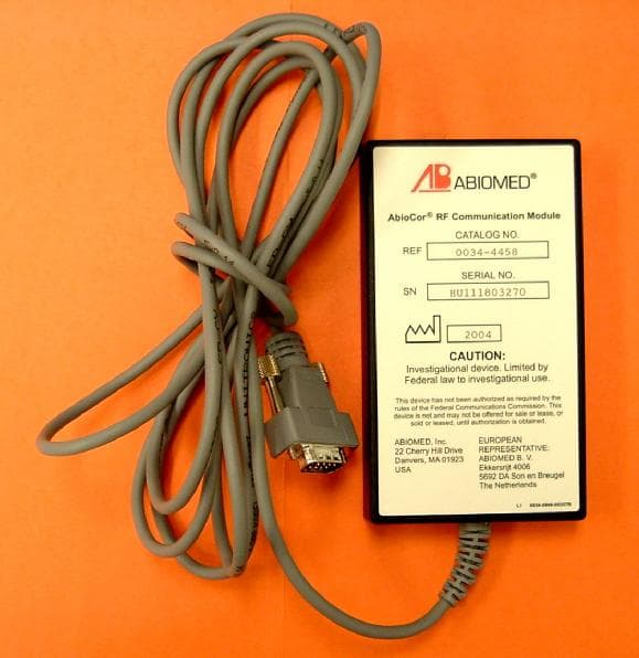
R9G0034-4458
Aug 02, 2004AbioCor RF Communication Module
Equipment Class
DXT - Part 15 Low Power Transceiver, Rx Verified