R9G-0036-0010SupraCor
ABIOMED Inc.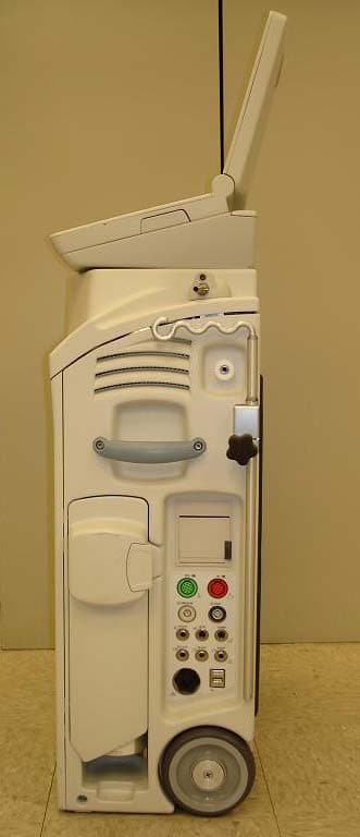
Click to zoom
Application Details
- Equipment Class
- FAP - Part 15 Anti-Pilferage Device
- Date of Grant
- Nov 19, 2006
- Application Purpose
- Original Equipment
- Date of Application
- Nov 19, 2006
- Equipment Note
- SupraCor
- Frequency Range
- 13.56000000 - 13.56000000
- Company
- ABIOMED Inc.
- Country
- United States
Documents & Files
Document Text
Text extracted from the exhibit documents filed with the FCC. Open a document above to read the original.
Users Manual
RECOVER BP IABP/VAD System Operator’s Manual ® RECOVER BP IABP/VAD System Operator’s Manual ABIOMED, Inc. 22 Cherry Hill Drive Danvers, MA 01923 USA 978-777-5410 978-777-8411 (fax) [email protected] (email) www.abiomed.com 24-Hour Emergency Hotline: N. America 1-800-422-8666 September 2006 DRAFT Document No. x Rev. 2 IMPORTANT NOTICE: Read this entire manual before using the RECOVER BP IABP/VAD System. The RECOVER BP IABP/VAD System is to be used only in accordance with this manual and in conjunction with the RECOVER BP Intra-Aortic Balloon Catheter Instructions for Use ****[document number]. Information contained in this document is subject to change without notice. © 2006 ABIOMED, Inc. All rights reserved. ABIOMED is a trademark of ABIOMED, Inc. and is registered in the U.S.A. RECOVER BP IABP/VAD System – Operator’s Manual iii Contents Introduction........................................................................ ix 1 Warnings and Cautions................................................ 1.1 Warnings...................................................................................................................... 1.2 Cautions.......................................................................................................................1.5 2 Indications, Contraindications, and Potential Adverse Events.................................................................. 2.1 Indications....................................................................................................................2.2 IABP...................................................................................................................... 2.2 VAD ...................................................................................................................... 2.2 Contraindications .........................................................................................................2.4 IABP...................................................................................................................... 2.4 VAD ...................................................................................................................... 2.4 Potential Adverse Events ............................................................................................. 2.4 IABP...................................................................................................................... 2.4 VAD ...................................................................................................................... 2.4 3 The RECOVER BP IABP/VAD System............................ 3.1 Overview ...................................................................................................................... 3.2 Disposables and Accessories...................................................................................... 3.3 IABP...................................................................................................................... 3.3 VAD ...................................................................................................................... 3.4 4 Using the RECOVER BP Console.................................. 4.1 Overview ...................................................................................................................... 4.2 Key Features ............................................................................................................... 4.3 Console Electrical Connections ................................................................................... 4.6 Keypad Layout ............................................................................................................. 4.7 Display Layout ............................................................................................................. 4.8 Menus ................................................................................................................... 4.8 Sample Screens ................................................................................................. 4.11 5 System Status and Settings........................................ 5.1 Using the Interface....................................................................................................... 5.2 iv RECOVER BP IABP/VAD System – Operator’s Manual System Menu ............................................................................................................... 5.3 Checking Console Power Status.................................................................................. 5.4 6 IABP Support................................................................ 6.1 Using the Interface ....................................................................................................... 6.2 IABP Keypad......................................................................................................... 6.2 IABP Screen ......................................................................................................... 6.4 Initial Setup ..................................................................................................................6.6 Acquiring an Electrocardiograph (ECG) Waveform............................................... 6.7 Acquiring an Arterial Pressure (AP) Waveform ..................................................... 6.8 Connecting the IAB to the Console ....................................................................... 6.9 Initiating Support ........................................................................................................6.10 To Initiate Support in Auto Mode:........................................................................ 6.10 To Initiate Support in Manual Mode:................................................................... 6.11 IABP Alarms............................................................................................................... 6.19 Levels of Severity..........................................…
Text truncated - open the document above for the full version.
External Photos
< ABIOMED CONFIDENTIAL > Page 1 of 4 0036-0010 Recover BP External Photos 0036-0010 Recover BP – Front View < ABIOMED CONFIDENTIAL > Page 2 of 4 0036-0010 Recover BP – Right Side View < ABIOMED CONFIDENTIAL > Page 3 of 4 0036-0010 Recover BP – Back View < ABIOMED CONFIDENTIAL > Page 4 of 4 0036-0010 Recover BP – Left Side View
Internal Photos
< ABIOMED CONFIDENTIAL > Page 1 of 7 0036-0010 Recover BP Internal Photos RFID Antenna RFID Transceiver Module 0036-0010 Recover BP – Front View < ABIOMED CONFIDENTIAL > Page 2 of 7 0036-0010 Recover BP – Front View (Close) < ABIOMED CONFIDENTIAL > Page 3 of 7 0036-0010 Recover BP – Inside Door View (Close) RFID Transceiver Module RFID Antenna 0036-0010 Recover BP – Top View < ABIOMED CONFIDENTIAL > Page 4 of 7 < ABIOMED CONFIDENTIAL > Page 5 of 7 RFID Transceiver Module 0036-0010 Recover BP – RFID Transceiver in Console (Close) < ABIOMED CONFIDENTIAL > Page 6 of 7 RFID Antenna 0036-0010 Recover BP – RFID Antenna & Coax Cable in Console (Close) < ABIOMED CONFIDENTIAL > Page 7 of 7 RFID Antenna RFID Transceiver Module 0036-0010 Recover BP – RFID Transceiver, Coax Cable and Antenna (Top & Bottom Views)
Test Report
Report Number 3094944BOX.001 Page 2 of 19 1.0 Job Description 1.1 Client Information This EUT has been tested at the request of: Company: Abiomed 22 Cherry Hill Drive Danvers, MA 01923 Contact: Ralph D’Ambrosio Telephone: Fax: Email: 978-646-1709 978-777-5692 [email protected] 1.2 Equipment Under Test Equipment Type: SupraCor Console Model Number(s): 0036-0010 Serial number(s): SC0101 Manufacturer: Abiomed EUT receive date: 3/13/2006 EUT received condition: Prototype in good condition Test start date: 3/13/2006 Test end date: 3/20/2006 1.3 Test Plan Reference: Tested according to the standards listed and ANSI C63.4:2003. 1.4 Test Configuration 1.4.1 Block Diagram SupraCor Console ECG-AP Simulator ECG Simulator AC Power Single AP ECG SPO 2 Coaxial x6 Dual AP Balloon Pressure Test Fixture Double Barrel Loop Test Fixture SupraCor Console Display Interface Report Number 3094944BOX.001 Page 3 of 19 1.4.2. Cables: Cable Shielding Connector Length (m) Qty. Coaxial Cables Coaxial Metal/BNC 1.5 6 SPO 2 Cable None Plastic 3 1 ECG Cable None Plastic 4.2 1 Dual AP Cable None Plastic 3.3 1 Single AP Cable None Plastic 3.3 1 AC Power Cable None Plastic 3 1 1.4.3. Support Equipment: Name: Model No.: Serial No.: Balloon Pressure Test Fixture N/L N/L Name: Model No.: Serial No.: Double Barrel Loop Test Fixture N/L N/L Name: Model No.: Serial No.: Netech ECG Patient Simulator MiniSim 9413 & 9414 1.5 Mode(s) of Operation: During testing, the RFID was transmitting repeatedly as it normally would during system operation. The EUT was tested as a floor-standing device. The SupraCor Console includes a display/interface which is hardwired as part of the console. Since the display/interface can be unclipped from the SupraCor Console main chassis and placed on a table with the interconnecting wiring extended, it was tested in this fashion. During the radiated emissions testing, only the transmitter was active in the EUT chassis. During the line- conducted emissions testing, the ECG, AP, Balloon Pump, and Ventricular Assist modes of the associated digital device were active. 1.6 Modifications Required for Compliance: A Wurth Elektronik ferrite, part number 74271132, was placed in a double loop configuration on the power and data line to the RF module (at the RF module). Report Number 3094944BOX.001 Page 4 of 19 2.0 Test Summary TEST STANDARD RESULTS FCC Part 15 Subpart C 15.225 SUB-TEST TEST PARAMETER COMMENT RF Output Power and Radiated Emissions FCC 15.205, 15.209, 15.225 RF Output Power is subject to the limits set forth in FCC Part 15.225, Spurious Emissions up to the tenth harmonic and in restricted bands are subject to the limits set forth in FCC Part 15.209. Spurious emissions must not exceed the fundamental field strength. Pass Frequency Stability FCC 15.225 The frequency drift of the carrier frequency must not exceed ±0.01% (100 PPM). Pass Line-Conducted Emissions FCC 15.207 Emissions must be below the 15.207 limits. Pass Notes: The RFID transmits at 13.56 MHz. REVISION SUMMARY – The following changes have been made to this Report: Date Project No. Project Handler Page(s) Item Description of Change Report Number 3094944BOX.001 Page 5 of 19 3.0 Sample Calculations The field strength is calculated by adding the Antenna Factor and Cable Factor, and subtracting the Amplifier Gain (if any) from the measured reading. The basic equation with a sample calculation is as follows: FS = RA + AF + CF - AG Where FS = Field Strength in dBμV/m RA = Receiver Amplitude (including preamplifier) in dBμV CF = Cable Attenuation Factor in dB AF = Antenna Factor in dB AG = Amplifier Gain in dB In the following table(s), the reading shown on the data table reflects the preamplifier gain. An example for the calculations in the following table is as follows. Assume a receiver reading of 52.0 dBμV is obtained. The antenna factor of 7.4 dB and cable factor of 1.6 dB is added. The amplifier gain of 29 dB is subtracted, giving a field strength of 32 dBμV/m. This value in dBμV/m was converted to its corresponding level in μV/m. RA = 52.0 dBμV AF = 7.4 dB/m CF = 1.6 dB AG = 29.0 dB FS = 32 dBμV/m Level in μV/m = [10( 32 dBμV/m)/20] = 39.8 μV/m The following is how net line-conducted readings were determined: NF = RF + LF + CF + AF Where NF = Net Reading in dBμV RF = Reading from receiver in dBμV LF = LISN Correction Factor in dB CF = Cable Correction Factor in dB AF = Attenuator Loss Factor in dB To convert from dBμV to μV or mV the following was used: UF = 10 (NF / 20) where UF = Net Reading in μV Example: NF = RF + LF + CF + AF = 28.5 + 0.2 + 0.4 + 20.0 = 49.1 dBμV UF = 10 (48.1 dBμV / 20) = 254 μV/m Report Number 3094944BOX.001 Page 6 of 19 3.1 Measurement Uncertainty Compliance of the product is based on the measured value. However, the measurement uncertainty is included for informational purposes. The expanded uncertainty (k = 2) for radiated emissions from 30 to 1000 MHz has been determined to be: ±3.5 dB at 10m, ±3.8 dB at 3m The expanded uncertainty (k = 2) for mains conducted emissions from 150 kHz to 30 MHz has been determined to be: ±2.6 dB The expanded uncertainty (k = 2) for telecom port conducted emissions from 150 kHz to 30 MHz has been determined to be: ±3.2 for ISN and voltage probe measurements ±3.1 for current probe measurements Report Number 3094944BOX.001 Page 7 of 19 3.2 Site Description Test Site(s): 2 Our OATS are 3m and 10m sheltered emissions measurement ranges located in a light commercial environment in Boxborough, Massachusetts. They meet the technical requirements of ANSI C63.4-2003 and CISPR 22:1993/EN 55022:1994 for radiated and conducted emission measurements. The shelter structure is entirely fiberglass and plastic, with outside dimensions of 33 ft x 57 ft. The structure resembles a quonset hut with a center ceiling height of 16.5 ft. The testing floor is covered by a galvanized sheet metal groundplane that is earth-grounded via copper rods around the perimeter of the site. The joints between indivi…
Text truncated - open the document above for the full version.
Test Setup Photos
Report Number 3094944BOX.001 Page 10 of 19 Radiated emissions setup photos Report Number 3094944BOX.001 Page 11 of 19 Report Number 3094944BOX.001 Page 16 of 19 Line-conducted emissions setup photos Line-Conducted Emissions, Front View, Ventricular Assist Mode Report Number 3094944BOX.001 Page 17 of 19 Line-Conducted Emissions, Back View, Ventricular Assist Mode Report Number 3094944BOX.001 Page 18 of 19 Line-Conducted Emissions, Front View, Balloon Pump Mode Report Number 3094944BOX.001 Page 19 of 19 Line-Conducted Emissions, Back View, Balloon Pump Mode
Contact Information
Applicant
Ralph L D'Ambrosio(Director, Electronic Engineering)
Technical Contact
ABIOMED IncRalph L D'Ambrosio
[email protected]978.646.1709
22 Cherry Hill Drive · Danvers, Massachusetts · United States
Non-Technical Contact
ABIOMED IncSheila M Flaherty
[email protected]978.646.1819
Test Firm
Intertek Testing Services NA Inc.Yaqing Liu
[email protected]978 635 8662
Technical Specifications
| # | Rule Parts | Frequency Range | Power Output |
|---|---|---|---|
| 1 | 15C | 13.56 MHz - 13.56 MHz | - |
Other Applications from ABIOMED Inc.
R9G0034-4590
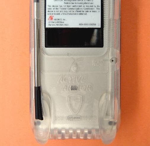
Nov 01, 2004AbioCor HandHeld Monitor
Equipment Class
DXT - Part 15 Low Power Transceiver, Rx Verified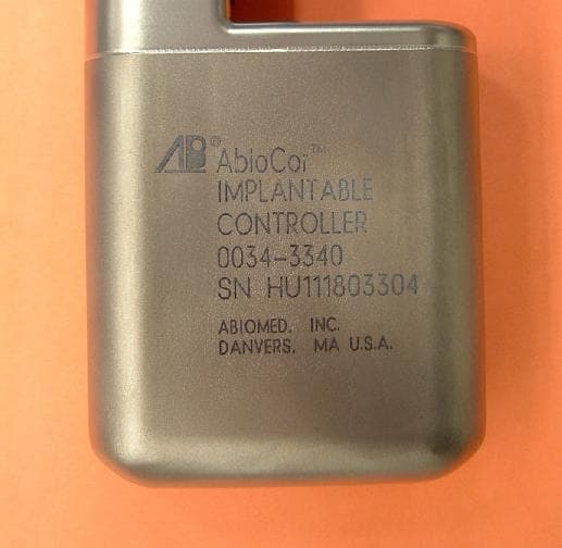
R9G-0034-3340
Oct 12, 2004AbioCor Implantable Controller
Equipment Class
DXT - Part 15 Low Power Transceiver, Rx Verified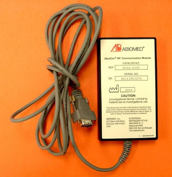
R9G0034-4458
Aug 02, 2004AbioCor RF Communication Module
Equipment Class
DXT - Part 15 Low Power Transceiver, Rx Verified