R9O-CONNEX1Single Wireless Gas Detector
BW Technologies Limited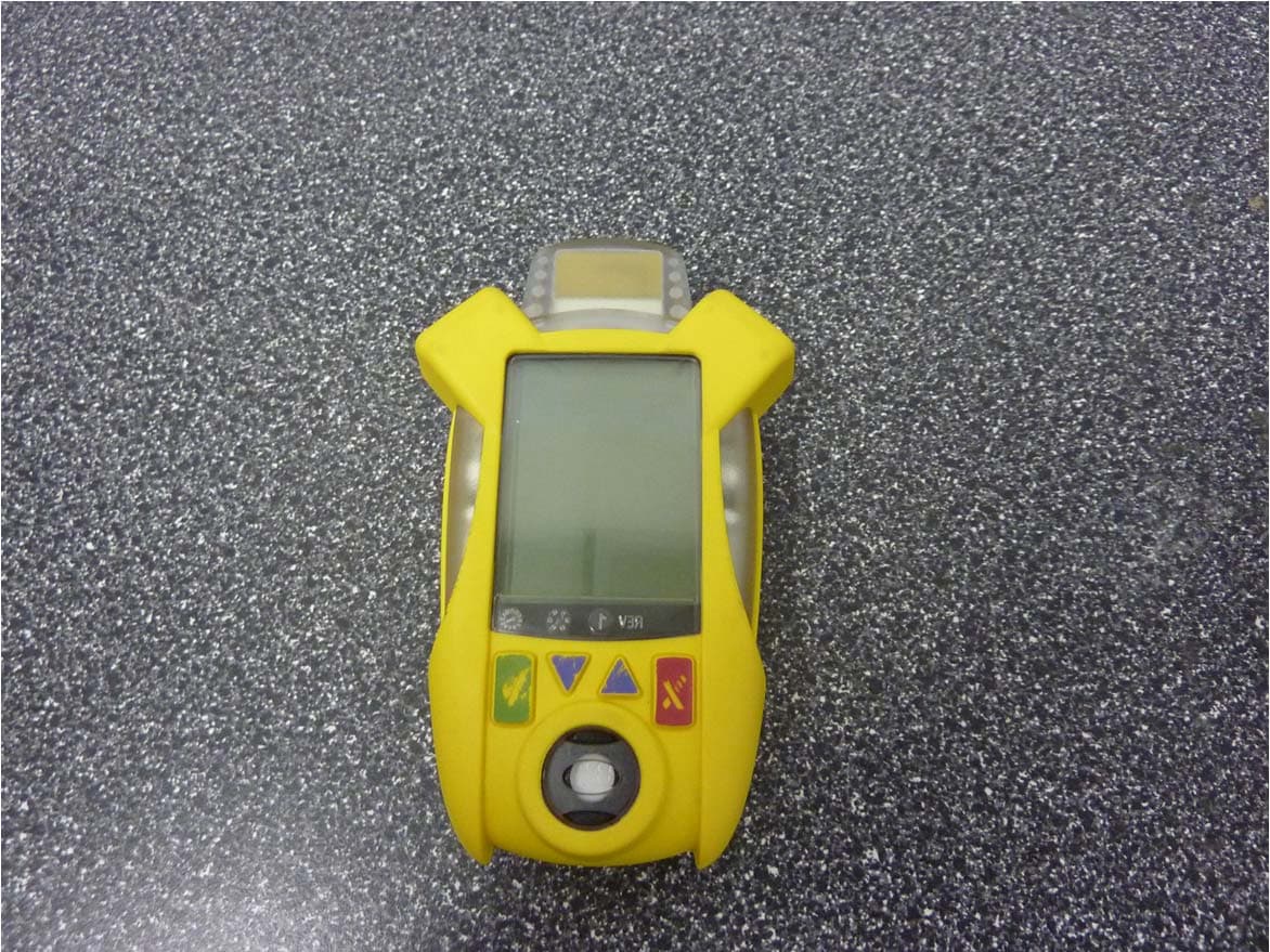
Click to zoom
Application Details
- Equipment Class
- DTS - Digital Transmission System
- Date of Grant
- May 16, 2012
- Application Purpose
- Original Equipment
- Date of Application
- May 09, 2012
- Equipment Note
- Single Wireless Gas Detector
- Frequency Range
- 2412.00000000 - 2462.00000000
- Company
- BW Technologies Limited
- Country
- Canada
Documents & Files
Document Text
Text extracted from the exhibit documents filed with the FCC. Open a document above to read the original.
Users Manual
Gas Detector Operator’s Manual ConneX1 Operator’s Manual i Limited Warranty and Limitation Liability BW Technologies by Honeywell LP (BW) warrants the product to be free from defects in material and workmanship under normal use and service for a period of two years, beginning on the date of shipment to the buyer. This warranty extends only to the sale of new and unused products to the original buyer. BW’s warranty obligation is limited, at BW’s option, to refund of the purchase price, repair or replacement of a defective product that is re turned to a BW authorized service center within the warranty period. In no event shall BW’s liability hereunder exceed the purchase price actually paid by the buyer for the Product. This warranty does not include: a. fuses, disposable batteries or the routine replacement of parts due to the normal wear and tear of the product arising from use; b. any product which in BW’s opinion, has been misused, altered, neglected or damaged, by accident or abnormal conditions of op eration, handling or use; c. any damage or defects attributable to repair of the product by any person other than an authorized dealer, or the installati on of unapproved parts on the product; or The obligations set forth in this warranty are conditional on: a. proper storage, installation, calibration, use, maintenance and compliance with the product manual instructions and any othe r applicable recommendations of BW; b. the buyer promptly notifying BW of any defect and, if required, promptly making the product available for correction. No goo ds shall be returned to BW until receipt by the buyer of shipping instructions from BW; and c. the right of BW to require that the buyer provide proof of purchase such as the original invoice, bill of sale or packing sl ip to establish that the product is within the warranty period. THE BUYER AGREES THAT THIS WARRANTY IS THE BUYER’S SOLE AND EXCLUSIVE REMEDY AND IS IN LIEU OF ALL OTHER WARRANTIES, EXPRESS OR IMPLIED, INCLUDING BUT NOT LIMITED TO ANY IMPLIED WARRANTY OF MERCHANTABILITY OR FITNESS FOR A PARTICULAR PURPOSE. BW SHALL NOT BE LIABLE FOR ANY SPECIAL, INDIRECT, INCIDENTAL, OR BASED ON CONTRACT, TORT OR RELIANCE OR ANY OTHER THEORY.Since some countries or states do not allow limitation of the term of an implied warranty, or exclusion or limitation of incide ntal or consequential damages, the limitations and exclusions of this warranty may not apply to every buyer. If any provision of this warranty is held invalid or unenforceabl e by a court of competent jurisdiction, such holding will not affect the validity or enforceability of any other provision. ConneX1 Operator’s Manual ii Contacting BW Technologies by Honeywell Corporate HeadquartersBW Technologies by Honeywell2840 2nd Ave. SECalgary, ABCanada T2A 7X9 +1.403.248.9226 / 1.800.663.4164 +1.403.573.3708 United StatesBW Technologies by Honeywell405 Barclay Blvd.Lincolnshire, ILUSA 60069 +1.847.955.8200 / 1.800.538.0363 +1.847.955.8210 EuropeBW Technologies by Honeywell4 Stinsford RoadNuffield Industrial EstatePoole, Dorset BH17 0RZ +44 (0) 1295.700.300 +44 (0) 1295.700.301 [email protected] ConneX1 Operator’s Manual iii 5.1 Break Mode................................................................................... 19 6. Panic Alarm ........................................................................................ 207. Alarms ................................................................................................ 217.1 Alarm Setpoints ................................................................................. 24 7.2 Stopping a Gas Alarm ................................................................... 24 7.2.1 Low and High Alarms ................................................................. 24 7.2.2 TWA and STEL Alarms ........................................................ 247.2.3 Acknowledging Latching Alarms .......................................... 24 8. Modes ................................................................................................. 24 8.1 Standard Operation ....................................................................... 24 8.2 Stealth Mode ................................................................................. 248.3 Safe Mode ..................................................................................... 24 8.4 Review Mode ................................................................................ 25 8.4.1 Gas Exposure ...................................................................... 258.4.2 Sensor Configuration ........................................................... 258.4.3 Detector Information ............................................................ 258.4.4 Messages ............................................................................. 25 9. Calibration .......................................................................................... 25 9.1 Calibration Using the IntelliDoX .................................................... 259.2 Calibration Guidelines ................................................................... 269.3 Installing the Calibration Cap ........................................................ 26 Table of Contents 1. Introduction .......................................................................................... 1 1.1 Intended Use................................................................................... 11.2 Product Overview ............................................................................ 2 1.2.1 Parts of the ConneX1 ............................................................. 2 1.2.2 Display Elements ................................................................... 31.2.3 Buttons ................................................................................... 4 1.3 Sensor Poisons and Contaminants ................................................. 5 2. Getting Started ...............................…
Text truncated - open the document above for the full version.
Users Manual
Exposure to RF Energy THIS MODEL DEVICE MEETS U.S. AND INTERNATIONAL REQUIREMENTS FOR EXPOSURE TO RADIO FREQUENCY RADIATION. The CONNEX1 is a radio transmitter and receiver. It is designed and manufactured not to exceed the emission limits for exposure to radio frequency (RF) energy set by the Federal Communications Commission of the U.S. Government and by the International Commission on Non-Ionizing Radiation Protection (ICNIRP). The device also meets the European Radio and Telecommunications Terminal Equipment (R&TTE) directive, for protecting the health and safety of the user and other persons. These limits are part of comprehensive guidelines that establish permitted levels of RF energy for the general population. The guidelines are based on standards that were developed by independent scientific organizations through periodic and thorough evaluation of scientific studies. The standards include a substantial safety margin designed to assure the safety of all persons, regardless of age and health. Before a device model is available for sale to the public, it must be tested and certified to operate within the limits for safe exposure established by the FCC and international organizations. The tests are performed in positions and locations (e.g., next to the body) as required by the FCC for each model. The FCC has granted an Equipment Authorization for this model device with all reported SAR levels (see below) evaluated as in compliance with the FCC RF emission guidelines. This device meets RF exposure guidelines when the antennas are positioned at a minimum distance from the body. In order to transmit data or messages, this device requires a quality connection to the network. In some cases, transmission of data or messages may be delayed until such a connection becomes available. Be sure that the recommended distance is observed until the transmission is complete. The exposure standard for wireless devices employs a unit of measurement known as the Specific Absorption Rate, or SAR. Tests for SAR are conducted using standard operating positions specified by the FCC with the device transmitting at its highest certified power level in all tested frequency bands. The SAR limit set by the FCC is 1.6 W/kg. The international guidelines state that the SAR limit for mobile devices used by the public is 2.0 W/kg averaged over 10 grams of body tissue. SAR values may vary depending on national reporting requirements and the network band. Although the SAR is determined at the highest certified power level, the actual SAR level of the device while operating can be well below the maximum value because the device operates at multiple power levels and uses only the power required to reach the network. SAR information on this model device is on file with the FCC and can be found under the Display Grant section a n d http://www.fcc.gov/oet/fccid after searching on FCC ID: R9O-CONNEX1 and IC: 5164A-CONNEX1 ____________________________________________________________________________________ ConneX1 Operator’s Manual
Attestation Statements
FCC ID: R9O-CONNEX1; IC: 5461-CONNEX1
Cover Letter(s)
Agent Authorization letter for radio certification FCC ID: R9O-CONNEX1; IC: 5461-CONNEX1 To whom so ever it may concern, Please be advised that BW Technologies, authorizes Suresh Kondapalli of TUV Rheinland of North America 1279 Quarry Lane, Suite A, Pleasanton California 94566 USA to act as agent on our behalf on all matters relating to applications for equipment authorizations before the Federal Communication Commission, including signing of documents related to these matters.
Cover Letter(s)
Subject: Confidentiality request FCC ID: R9O-CONNEX1 IC: 5164A-CONNEX1 Type of Confidentiality Requested Exhibit Short Term Permanent Block Diagrams Short Term Permanent Internal Photos Short Term Permanent Operation Description/Theory of Operation Short Term Permanent Tune-Up Procedure Short Term Permanent Schematics Short Term Permanent User’s Manual
External Photos
External Photos
ID Label/Location Info
A 04-16-12 50104703-001 Individual labels per gas type, per region 01A 04-23-12 50104703-001 Changed M: for Model: 02A 04-23-12 50104703-001 Removed IEC labels. Updated artwork LABEL ARTWORK as printed @ 150% NA - H2S LABEL ARTWORK as printed @ 150% NA - SO2 LABEL ARTWORK as printed @ 150% NA - CO LABEL ARTWORK as printed @ 150% NA - O2 NA Model: FCC ID: R90-CONNEX1 IC: 5164A-CONNEX1 Understand manual before operating Canada T2A 7X9 WARNING: Battery must be charged in a non-hazardous area and may only be replaced by the manufacturer. Noncompliance might cause explosion danger. Intrinsically safe CI. I Div. I Gr. A,B,C,D T4 AEx ia IIC T4 Haz locs. -20 ̊C ≤ Ta ≤ +55 ̊C 4.2 Vdc Battery powered NA S1 FCC ID: R90-CONNEX1 IC: 5164A-CONNEX1 Understand manual before operating Canada T2A 7X9 WARNING: Battery must be charged in a non-hazardous area and may only be replaced by the manufacturer. Noncompliance might cause explosion danger. Intrinsically safe CI. I Div. I Gr. A,B,C,D T4 AEx ia IIC T4 Haz locs. -20 ̊C ≤ Ta ≤ +55 ̊C 4.2 Vdc Battery powered NAM1 FCC ID: R90-CONNEX1 IC: 5164A-CONNEX1 Understand manual before operating Canada T2A 7X9 WARNING: Battery must be charged in a non-hazardous area and may only be replaced by the manufacturer. Noncompliance might cause explosion danger. Intrinsically safe CI. I Div. I Gr. A,B,C,D T4 AEx ia IIC T4 Haz locs. -20 ̊C ≤ Ta ≤ +55 ̊C 4.2 Vdc Battery powered NA X1 FCC ID: R90-CONNEX1 IC: 5164A-CONNEX1 Understand manual before operating Canada T2A 7X9 WARNING: Battery must be charged in a non-hazardous area and may only be replaced by the manufacturer. Noncompliance might cause explosion danger. Intrinsically safe CI. I Div. I Gr. A,B,C,D T4 AEx ia IIC T4 Haz locs. -20 ̊C ≤ Ta ≤ +55 ̊C 4.2 Vdc Battery powered Model: Model: Model: 7 654 24-Feb-2012 PS 321 File: CONX1D-64_certification_labels.ai Date: Date: Approved: Part #ECO # Description Rev Drawn by: AG Scale: As Noted. Sheet: 1 of 1 Dwg #: CONX1D-64 Layer NA / IEC labels. SN / MN location BW Technologies by Honeywell Calgary, Alberta by Honeywell
ID Label/Location Info
DEMO FCC ID: R90-CONNEX1 IC: 5164A-CONNEX1 Understand manual before operating Canada T2A 7X9 WARNING: Battery must be charged in a non-hazardous area and may only be replaced by the manufacturer. Noncompliance might cause explosion danger. C22.2 No. 152, x12.13 Intrinsically safe CI. I Div. I Gr. A,B,C,D T4 AEx ia II T4 Haz locs. -20 ̊C ≤ Ta ≤ +50 ̊C 4.2 Vdc 04A 16-10-12 50104703-001 Split into NA, EU and IEC labels 05A 26-10-12 50104703-001 Resized CE, FCC and C-tick. Add A-tick and Gost-R 06A 02-02-12 50104703-001 Update Ex to AEx, temperature changed to 50C 07A 02-07-12 50104703-001 Part num. revised. Type point size and leading increased 08A 02-24-12 50104703-001 FCC and IC numbers updated as per Paul S. LABEL ARTWORK @ 100% LABEL ARTWORK @ 150% AS PRINTED @ 100% ConneX1 Model # Legend Date Code & Serial # Legend 5345CNX01112201000 Plant code Product ID Revision # Serial number Week of manufacture Year of manufacture CONNEX1-H Sensor (see Table A) Product ConneX1 label location FCC ID: R90-CONNEX1 IC: 5164A-CONNEX1 Understand manual before operating Canada T2A 7X9 WARNING: Battery must be charged in a non-hazardous area and may only be replaced by the manufacturer. Noncompliance might cause explosion danger. C22.2 No. 152, x12.13 Intrinsically safe CI. I Div. I Gr. A,B,C,D T4 AEx ia II T4 Haz locs. -20 ̊C ≤ Ta ≤ +50 ̊C 4.2 Vdc 42.40 23.94 23.91 7 654 24-Feb-2012 PS 321 File: CONX1A-01_certification_America.ai Date: Date: Approved: Part #ECO # Description Rev Drawn by: AG Scale: As Noted. Sheet: 1 of 1 Dwg #: CONX1A-01 Layer Connex1 Americas Certification Label Notes: 1. Blank: 3M 7872, 2.0 mil Thermal Transfer Polyester Label material Colour: Black thermal print on matte platinum background. Adhesive: 3M 350, 1.8 mil acrylic Ribbon: Sony TR5070 ERP# 50104701-001 2. Barcodes to be printed Data Matrix 3. All dimensions in mm. BW Technologies by Honeywell Calgary, Alberta by Honeywell
Internal Photos
Internal Photos Production Model of ConneX1 with Radio module potted Preproduction model of ConneX1 with Radio module uncovered
RF Exposure Info
802 N. Twin Oaks Valley Road, Suite 105 • San Marcos, CA 92069 • U.S.A. TEL (760) 471-2100 • FAX (760) 471-2121 http://www.rfexposurelab.com CERTIFICATE OF COMPLIANCE SAR EVALUATION BW Technologies Dates of Test: March 22, 2012 2840 2 nd Avenue SE Test Report Number: SAR.20120303 Calgary, Alberta, Canada T2A 7X9 FCC ID: R90-CONNEX1 IC Certificate: 5164A-CONNEX1 Model(s): ConneX1 Test Sample: Engineering Unit Same as Production MAC Address: 5345CNX01114300181 Equipment Type: Wireless Gas Detector Classification: Portable Transmitter Next to Body TX Frequency Range: 2412 – 2462 MHz Frequency Tolerance: ± 2.5 ppm Maximum RF Output: 2450 MHz (b) – 18.31 dB Peak Conducted Signal Modulation: DSSS, OFDM Antenna Type: Internal Application Type: Certification FCC Rule Parts: Part 2, 15C KDB Test Methodology: KDB 447498, KDB 248227 Industry Canada: RSS-102, Safety Code 6 Maximum SAR Value: 0.840 W/kg Separation Distance: 0 mm This wireless mobile and/or portable device has been shown to be compliant for localized specific absorption rate (SAR) for uncontrolled environment/general exposure limits specified in ANSI/IEEE Std. C95.1-1992 and had been tested in accordance with the measurement procedures specified in IEEE 1528-2003, and OET Bulletin 65 Supp. C (See test report). I attest to the accuracy of the data. All measurements were performed by myself or were made under my supervision and are correct to the best of my knowledge and belief. I assume full responsibility for the completeness of these measurements and vouch for the qualifications of all persons taking them. RF Exposure Lab, LLC certifies that no party to this application is subject to a denial of Federal benefits that includes FCC benefits pursuant to Section 5301 of the Anti-Drug Abuse Act of 1988, 21 U.S.C. 853(a). Jay M. Moulton Vice President Certificate # 2387.01 © 2012 RF Exposure Lab, LLC This report shall not be reproduced except in full without the written approval of RF Exposure Lab, LLC. FCC ID: R90-CONNEX1 Table of Contents 1. Introduction ........................................................................................................................... 3 SAR Definition [5] ...................................................................................................................... 3 2. SAR Measurement Setup ..................................................................................................... 4 Robotic System ......................................................................................................................... 4 System Hardware ..................................................................................................................... 4 System Description ................................................................................................................... 4 E-Field Probe ............................................................................................................................ 5 3. Robot Specifications ............................................................................................................. 7 4. Probe and Dipole Calibration ................................................................................................ 8 5. Phantom & Simulating Tissue Specifications ........................................................................ 9 SAM Phantom ........................................................................................................................... 9 Head & Body Simulating Mixture Characterization ................................................................... 9 Device Holder ........................................................................................................................... 9 6. ANSI/IEEE C95.1 – 1992 RF Exposure Limits [2] ............................................................... 10 Uncontrolled Environment ....................................................................................................... 10 Controlled Environment .......................................................................................................... 10 7. Measurement Uncertainty ................................................................................................... 11 8. System Validation ............................................................................................................... 12 Tissue Verification ................................................................................................................... 12 Test System Verification ......................................................................................................... 12 9. SAR Test Data Summary .................................................................................................... 13 Procedures Used To Establish Test Signal ............................................................................. 13 Device Test Condition ............................................................................................................. 13 SAR Data Summary – 2450 MHz Body 802.11b .................................................................... 14 11. Test Equipment List ........................................................................................................ 15 12. Conclusion ...................................................................................................................... 16 13. References ...................................................................................................................... 17 Appendix A – System Validation Plots and Data ........................................................................ 18 Appendix B – SAR Test Data Plots ............................................................................................. 22 Appendix C – SAR Test Setup Photos ....................................................................................... 30 Appendix D – Probe Calibr…
Text truncated - open the document above for the full version.
Test Report
Report Number: 31153356.001 Page 1 of 75 EUT: Single Wireless Gas Detector Models: CNX1-X1-Y-NA, CNX1-H1-Y-NA, CNX1-M1-Y-NA and CNX1-S1-Y-NA EMC / Rev 3/20/2012 FCCID: R90-CONNEX1; IC: 5164A-CONNEX1 Emissions Test Report EUT Name: Single Wireless Gas Detector Model No: CNX1-X1-Y-NA, CNX1-H1-Y-NA, CNX1-M1-Y-NA and CNX1-S1-Y-NA CFR 47 Part 15.247 2009 and RSS 210: 2010 Prepared for: Paul Silva BW Technologies, LTD. 2840 2nd Avenue SE Calgary, Alberta, Canada T2A 7X9 Tel: 781-708-6777 Prepared by: TUV Rheinland of North America, Inc. 1279 Quarry Lane Pleasanton, CA 94566 Tel: (925) 249-9123 Fax: (925) 249-9124 http://www.tuv.com/ Report/Issue Date: March 31, 2012 Report Number: 31153356.001 Statement of Compliance Report Number: 31153356.001 Page 2 of 75 EUT: Single Wireless Gas Detector Models: CNX1-X1-Y-NA, CNX1-H1-Y-NA, CNX1-M1-Y-NA and CNX1-S1-Y-NA EMC / Rev 3/20/2012 FCCID: R90-CONNEX1; IC: 5164A-CONNEX1 Manufacturer: BW Technologies, LTD. 2840 2nd Avenue SE Calgary, Alberta, Canada T2A 7X9 Requester / Applicant: Paul Silva Name of Equipment: Single Wireless Gas Detector Model No. CNX1-X1-Y-NA, CNX1-H1-Y-NA, CNX1-M1-Y-NA and CNX1- S1-Y-NA Type of Equipment: Intentional Radiator Application of Regulations: CFR 47 Part 15.247 2009 and RSS 210: 2010 Test Dates: February 01 to Feb 29, 2012 Guidance Documents: Emissions: ANSI C63.10-2009 Test Methods: Emissions: ANSI C63.10-2009 The electromagnetic compatibility test and documented data described in this report has been performed and recorded by TUV Rheinland, in accordance with the standards and procedures listed herein. As the responsible authorized agent of the EMC laboratory, I hereby declare that the equipment described above has been shown to be compliant with the EMC requirements of the stated regulations and standards based on these results. If any special accessories and/or modifications were required for compliance, they are listed in the Executive Summary of this report. This report must not be used to claim product endorsement by NVLAP or any agency of the U.S. Government. This report contains data that are not covered by NVLAP accreditation. This report shall not be reproduced except in full, without the written authorization of TUV Rheinland of North America. Suresh Kondapalli March 31, 2012 Conan Boyle March 31, 2012 Test Engineer Date NVLAP Signatory Date Industry Canada 500011-0 US5254 2932M-1 Index of Tables Report Number: 31153356.001 Page 3 of 75 EUT: Single Gas Wireless Detector Models: CNX1-X1-Y-NA, CNX1-H1-Y-NA, CNX1-M1-Y-NA and CNX1-S1-Y-NA EMC / Rev 3/20/2012 FCCID: R90-CONNEX1; IC: 5164A-CONNEX1 1 Executive Summary _______________________________________________________ 6 1.1 Scope______________________________________________________________________ 6 1.2 Purpose____________________________________________________________________ 6 1.3 Summary of Test Results _____________________________________________________ 6 1.3.1 Measured values of key parameters ____________________________________________________ 7 1.4 Special Accessories __________________________________________________________ 7 1.5 Equipment Modifications _____________________________________________________ 7 2 Laboratory Information ____________________________________________________ 8 2.1 Accreditations & Endorsements _______________________________________________ 8 2.1.1 US Federal Communications Commission _______________________________________________ 8 2.1.2 NIST / NVLAP ____________________________________________________________________ 8 2.1.3 Canada – Industry Canada ___________________________________________________________ 8 2.1.4 Japan – VCCI _____________________________________________________________________ 8 2.1.5 Acceptance by Mutual Recognition Arrangement _________________________________________ 9 2.2 Test Facilities _______________________________________________________________ 9 2.2.1 Emission Test Facility ______________________________________________________________ 9 2.2.2 Immunity Test Facility ______________________________________________________________ 9 2.3 Measurement Uncertainty ___________________________________________________ 10 2.3.1 Sample Calculation – radiated & conducted emissions ____________________________________ 10 2.3.2 Measurement Uncertainty ___________________________________________________________ 10 2.4 Calibration Traceability _____________________________________________________ 11 3 Product Information ______________________________________________________ 12 3.1 Product Description ________________________________________________________ 12 3.2 Equipment Configuration ___________________________________________________ 12 3.3 Operating Mode ___________________________________________________________ 13 3.4 Duty Cycle: _______________________________________________________________ 13 3.5 Unique Antenna Connector __________________________________________________ 14 3.5.1 Results _________________________________________________________________________ 14 4 Emission Requirements – 2400 MHz to 2483.5 MHz Band _______________________ 15 4.1 Output Power Requirements _________________________________________________ 15 4.1.1 Test Method _____________________________________________________________________ 15 4.1.2 Results _________________________________________________________________________ 16 4.2 Occupied Bandwidth _______________________________________________________ 20 4.2.1 Test Method _____________________________________________________________________ 20 4.2.2 Results _________________________________________________________________________ 21 4.3 Band-edge Requirements ____________________________________________________ 25 4.3.1 Results _________________________________________________________________________ 25 Index of Tables Report Number: 31153356.001 Page 4 of 75 EUT: Single Gas Wireless Detector Models: CNX1-X1-Y-NA, CNX1-H1-Y-NA, CNX1-M1-Y-NA and CNX1-S1-Y-NA EMC / Re…
Text truncated - open the document above for the full version.
Test Setup Photos
Test Setup Photos (FCCID: R90-CONNEX1; IC: 5164A-CONNEX1)
Contact Information
Applicant
Bonnie Saxinger(Manager, Product Compliance)
Test Firm
TUV Rheinland of North America Inc.Kent Chesley
Technical Specifications
| # | Rule Parts | Frequency Range | Power Output |
|---|---|---|---|
| 1 | 15C | 2.41 GHz - 2.46 GHz | 16.30 mW |
Other Applications from BW Technologies Limited
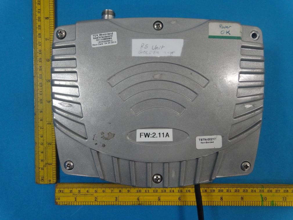
R9O-LADC101
May 28, 2014LocaXion Anchor Wireless Transceiver
Equipment Class
DTS - Digital Transmission System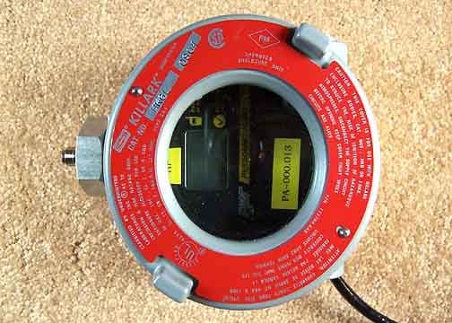
R9O-PAHE-10
Aug 28, 2005Personnel Alert Base
Equipment Class
DSS - Part 15 Spread Spectrum Transmitter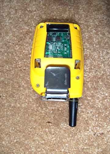
R9O-PASE-10
Aug 28, 2005Personnel Alert Badge
Equipment Class
DSS - Part 15 Spread Spectrum Transmitter