RA30009260177PS2 Wireless AirFlo Controller
Nyko Technologies, Inc.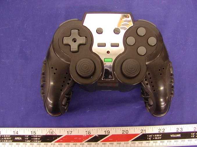
Click to zoom
Application Details
- Equipment Class
- DXX - Part 15 Low Power Communication Device Transmitter
- Date of Grant
- Jan 28, 2004
- Application Purpose
- Original Equipment
- Date of Application
- Jan 28, 2004
- Equipment Note
- PS2 Wireless AirFlo Controller
- Frequency Range
- 908.05800000 - 922.80300000
- Company
- Nyko Technologies, Inc.
- Country
- United States
Documents & Files
Document Text
Text extracted from the exhibit documents filed with the FCC. Open a document above to read the original.
Users Manual
Instructions for Air Flo ™ Wireless Controller — Item # 80503 Thank you for purchasing the NYKO Air Flo ™ Wireless controller for the PlayStation®2, PlayStation® or PSone ™ entertainment consoles. This controller provides unparalleled comfort in wireless gaming without sacrificing control or accuracy. Please take note of the CARE AND MAINTENANCE guidelines to ensure long life and problem-free performance. FEATURES • Adjustable Air Flo ™ hand cooling technology eliminates perspiration and fatigue during game play • 8 selectable wireless channels for multi-player wireless gaming • Dual analog control sticks • Vented and rubberized comfort grips for control and comfort • 8-way directional pad • Long range RF wireless technology ensures lag-free response with no line-of- sight interference • Automatic Sleep Mode saves battery life when the controller is not in use • Detachable D-pad joystick and rubber feet for arcade-style play • Pressure sensitive buttons QUICK START GUIDE 1. Remove battery compartment lid on the back of the Controller. 2. The detachable joystick stores in the bottom of the battery compartment for safe keeping. If you wish to use the joystick, remove it before inserting the batteries. 3. Insert 4 "AA" batteries as shown by the diagram printed in the compartment. NOTE: A battery ribbon is provided to aid in the removal of the batteries. As you insert the batteries, fold the ribbon over each layer for easy replacement later. 4. Replace the battery compartment lid. 5. Set the Wireless Channel by rotating the CHANNEL knob to any position from 1 to 8. NOTE: If you have multiple Air Flo Wireless controllers, you will need to select a different channel number for each Controller. 6. Set the slide switch on the side of the Receiver to match the Channel number you have selected on the Controller. 7. Insert the Receiver into an open controller slot on the PlayStation console. 8. Turn the PlayStation ON. 9. Turn on the Air Flo Wireless controller by pressing the green POWER button. USING THE AIR FLO FEATURE The Air Flo Wireless controller provides the latest advances in our award winning Air Flo technology. While earlier Air Flo models provide two modes of Air Flo fan speed, this model provides a variable speed FAN control knob that allows you to set a custom cooling level. To activate the hand cooling feature, simply turn the FAN knob clockwise. The SPEED of the fan increases gradually as you turn the knob. Set the cooling level to the desired level. To turn the fan OFF, simply turn the FAN knob all the way counter-clockwise. USING THE DETACHABLE JOYSTICK The Air Flo Wireless controller provides a detachable joystick, which can screw into the D-pad in order to simulate an arcade stick game pad. This configuration can be very useful when playing certain types of games. There is a special cavity provided for storage of the joystick when not in use, located at the bottom the battery compartment of the Air Flo Wireless controller. The batteries will need to be removed in order to access the storage space. When replacing batteries, fold the battery ribbon around the battery layers to ensure quick, easy access to the joystick storage space. When attaching the joystick, make sure the screw threads are correctly aligned to avoid damage. Never screw the stick into place too tightly. Doing so may cause the joystick to get stuck and risk damage during removal. WARNING: THIS ITEM INCLUDES SMALL PARTS THAT MAY POSE A CHOKING HAZARD IF PLACED IN THE MOUTH OR SWALLOWED. NEVER PLACE THE JOYSTICK IN YOUR MOUTH. KEEP SMALL PARTS AWAY FROM CHILDREN. TROUBLESHOOTING • Make sure the CHANNEL selected on the Controller matches the CHANNEL selection on the Receiver. • Set the CHANNEL numbers before turning game console ON. • If the Controller does not respond well, try selecting a different CHANNEL number on the Controller and the Receiver. • Make sure that the batteries have sufficient charge to power the unit. • Make sure that the batteries are placed into the battery compartment in the proper orientation. • Make sure that the Receiver is fully inserted into the controller port. • Make sure that the LED light above the green POWER button is ON. If LED light is not lit, press the POWER/MODE button to turn the unit ON. CARE AND MAINTENANCE Please review the following guidelines to ensure optimal performance from the Air Flo Wireless controller. Failure to follow these guidelines may cause damage to the controller not covered by your NYKO Warranty. • Do not expose this controller to extreme conditions, including direct sunlight or excessive heat and humidity. • Protect the controller from exposure to liquids or small objects of any kind. • Be careful when using the various rotary knobs on the controller. These are delicate parts and should not be forced beyond their limits or tampered with. • Never use chemicals to clean the controller. If cleaning is necessary, unplug the controller and use a slightly damp cloth to clean the affected area. • When not in use, store the Receiver and other small parts included with this item in a safe place to avoid loss or damage. • When not in use, store the removable joystick in its special cavity in the battery compartment to avoid loss or damage. • Stop use if the controller performs abnormally. NYKO Product Limited Warranty This NYKO product is warranted to the original purchaser for the normal intended use for a period of ninety (90) days from the date of purchase. If a defect covered under this warranty occurs, NYKO will replace or repair the product or its defective parts, at its option, at no charge. Warranty does not apply to defects resulting from modification or misuse of this product. The product can be returned to the place of purchase accompanied with proof of purchase or shipped to: NYKO Technologies Inc., P.O. Box 46697, Los Angeles, CA 90064, with freight charges prepaid. Please allow 3-4 weeks for processing. INSTRUCTIONS AND WARRANTY INFORMATION Item# 805…
Text truncated - open the document above for the full version.
Block Diagram
Block Diagram Receiver Connector to PlayStation Microprocessor RF radio receiver RSSI Measurement DC power 14.7456 MHz Xtal Transmitter Microprocessor RF radio Transmitter Joypad Interface 4-cell AA batteries 3.3V Power to circuits 14.7456 MHz Xtal
External Photos
EXHIBIT C - EUT EXTERNAL PHOTOGRAPHS EUT – Chassis Top View EUT – Chassis Bottom View EUT – Chassis Rear View
ID Label/Location Info
EXHIBIT A - FCC ID LABEL INFORMATION Proposed FCC ID Label Specifications: Text is black or white in color and is left justified. Labels are silk- screened and shall be “permanently affixed” at a conspicuous location on the EUT. Proposed Label Location on EUT EUT Bottom View / Proposed FCC ID Label Location FCC ID: RA30009260177 This device complies with Part 15 o the FCC Rules. Operation is subject to the following two conditions: (1) this device may not cause harmful interference, and (2) this device must accept any interference received, including interference that may cause undesired operation. 2.1875" 1.0" Label Here
Internal Photos
EXHIBIT C - EUT INTERNAL PHOTOGRAPHS EUT – Chassis Cover Off View EUT – Main Board Component View EUT – Main Board Solder View
Operational Description
Wireless Joypad for Sony PlayStation Theory of Operation 12/8/03 1. Joypad Side Radio Transmitter Joypad side radio is a radio transmitter operates in the frequency range of 908.058 – 922.803 MHz.in divided in 8 RF channels. It has a radio transmitter and a baseband processor. The baseband processor takes data from game controller, packetizes the data, and transmits them. When powered on, the baseband processor scans keystrokes on the joypad, packetizes the keystroke data, and transmits the command with the keystroke data to the Station Side Radio receiver at the data rate of 76.8 kbps. The transmitter has 8 dedicated channels which can be selected manually by the user via rotary switch. The joypad radio transmitter is powered by 4-AA size batteries and down regulated to 3.3V. The total average power consumption of the radio transmitter is about 12.7 mA at 3.3V. 2. Station Side Radio Receiver The radio receiver is mainly composed of two parts: radio receiver, and baseband microprocessor. The radio receiver is interfaced with Sony PlayStation via a 9-pin connector via a baseband processor. The receiver receives keystroke data from radio transmitter described in Section 1, depacketizes the data, and sends the data to Sony PlayStation every 16 milliseconds. The radio receiver is a FSK receiver running at 76.8 kbps. Frequency is controlled by a frequency synthesizer which adjusts a voltage- controlled RF oscillator dynamically for accurate frequency management. Channel is set by a selecting an 8-position slide switch. A total of 8 channels can be selected conversing the frequency range of 908.058 – 922.803 MHz. The antenna is an embedded PCB antenna matching is done by using lumped inductors and capacitors. The radio is powered by a 3.3V power source provided by Sony PlayStation.
Schematics
Transmitter Schematics BW_GC 1 GC_Stick_MCU (EM78P257 CC1050) B 24 Monday, December 08, 2003 TitleSize Document Number Rev Date: Sheet of +3.3V +3.3V +3.3V 3.3V +6V +6V +6V +3.3V +3.3V +3.3V +6V +3.3V DIO PALEPCLK PDATA JS_CLK JS_CS JS_DOUTJS_DIN DCLK PALE PDATA PCLK DCLK DIO JS_CSJS_CLKJS_DINJS_DOUT Wakeup_CNT LED_CNTVDetect VShutdown VLow Wake_Up CH_SEL1CH_SEL3CH_SEL2 Wake_Up Analog Wakeup_CNT LED_CNTVDetectVLowCH_SEL1 AnalogCH_SEL3VShutdownCH_SEL2 R23100K J6DCLK 1 R22 2.2k C4100nF J5DIO 1 C1100nF R1920K R2991K R17 10k R14 10k R30110KR25240K R31 0 1 2 R20100 U3 AIC1733 Vin 1 GND 2 CNT 3 Vout 5 Bypass 4 R21240K R24240K U2EM78P257 P56 1 P52 2 P53 3 P54 4 P71 5 VSS 6 INT/P60 7 P61 8 P62 9 P63 10 P64 11 P65/CIN4+ 12 P67 14 VDD 15 P70/OSCO 16 P55/OSCI 17 P50 18 P51 19 P57 20 P66/CIN4- 13 R2611k R2811k R2711k C310uF/6V + R15 10k R16 1k R1810K SW11RSW3 3 12 D1Analog LED 1 2 J171Rotary SW 1 1 GND 2 4th 3 8th 6 GND 5 2nd 4 J172Battary + 1 J173CON1 1 C19100uF/10V + U5EM78P257_Bonding P56 1 P52 2 P53 3 P54 4 P71 5 VSS 6 INT/P60 7 P61 8 P62 9 P63 10 P64 11 P65/CIN4+ 12 P67 14 VDD 15 P70/OSCO 16 P55/OSCI 17 P50 18 P51 19 P57 20 P66/CIN4- 13 C2010uF/6V + {Doc} {RevCode} {Title} A 34 Friday, November 14, 2003 TitleSize Document Number Rev Date: Sheet of {Doc} {RevCode} Transmitter A 34 Friday, November 14, 2003 TitleSize Document Number Rev Date: Sheet of 3.3V 3.3V 3.3V PALEPDATAPCLKDCLKDIO CHP_OUT X114.7456MHz C131nF L4 5.6nH L5 BLM11A102S C54.7pF L24pF ANT1ANTENNA ANT2ANTENNA C65.6pF L1 2.5nH C10 33nF U4 CC1050 L1 5 AGND4 4 AGND3 3 AVDD7 7 AVDD11 11 RF_OUT 24 PCLK 21 DCLK 20 DIO 19 AGND2 2 PDATA 22 DVDD17 17 DGND18 18 PALE 23 AVDD1 1 L2 6 CHP_OUT 8 R_BIAS 9 AGND15 15 AGND12 12 XOSC_Q2 13 XOSC_Q1 14 DGND16 16 AGND10 10 J75CON1 1 J72CON1 1 J71CON1 1 J69CON1 1 J79CON1 1 J73CON1 1 J78CON1 1 J77CON1 1 J74CON1 1 J76CON1 1 J70CON1 1 C8 220pF C982pF C1718pF R3282K C1818pF C70pF C1433nF
Test Report
Note: This test report is specially limited to the above client company and the product model only. It may not be duplicated without prior written consent of Bay Area Compliance Laboratory Corporation. This report must not be used by the client to claim product endorsement by NVLAP or any agency of the U.S. Government. FCC PART 15 Subpart C EMI MEASUREMENT AND TEST REPORT For Nyko Technologies, Inc. 1990 Westwood Boulevard, Penthouse Suite Los Angeles, CA 90025 FCC ID: RA30009260177 2004-01-26 This Report Concerns: Original Report Equipment Type: Air Flo Wireless for PlayStation Test Engineer: Benjamin Jin Report No.: R0312173 Test Date: 2003-12-23 Reviewed By: Ling Zhang Prepared By: Bay Area Compliance Laboratory Corporation 230 Commercial Street Sunnyvale, CA 94085 Tel (408) 732-9162 Fax (408) 732-9164 Nyko Technologies, Inc. FCC ID: RA30009260177 Report # R0312173Rpt.doc Page 2 of 18 FCC Part 15.249 Test Report TABLE OF CONTENTS GENERAL INFORMATION.......................................................................................................................................3 PRODUCT DESCRIPTION FOR EQUIPMENT UNDER TEST (EUT) ....................................................................................3 OBJECTIVE...................................................................................................................................................................3 RELATED SUBMITTAL(S)/GRANT(S).............................................................................................................................3 TEST METHODOLOGY..................................................................................................................................................3 TEST FACILITY.............................................................................................................................................................3 SYSTEM TEST CONFIGURATION ..........................................................................................................................5 DESCRIPTION OF TEST CONFIGURATION......................................................................................................................5 EQUIPMENT MODIFICATIONS.......................................................................................................................................5 CONFIGURATION OF TEST SYSTEM..............................................................................................................................5 TEST SETUP BLOCK DIAGRAM.....................................................................................................................................5 SUMMARY OF TEST RESULTS ...............................................................................................................................6 §15.203 - ANTENNA REQUIREMENT......................................................................................................................7 STANDARD APPLICABLE..............................................................................................................................................7 ANTENNA CONNECTED CONSTRUCTION......................................................................................................................7 §15.209(A) - RADIATED EMISSION DATA .............................................................................................................8 MEASUREMENT UNCERTAINTY....................................................................................................................................8 EUT SETUP..................................................................................................................................................................8 SPECTRUM ANALYZER SETUP......................................................................................................................................8 TEST EQUIPMENT LIST AND DETAILS...........................................................................................................................8 TEST PROCEDURE........................................................................................................................................................9 CORRECTED AMPLITUDE & MARGIN CALCULATION...................................................................................................9 SUMMARY OF TEST RESULTS.......................................................................................................................................9 RADIATED EMISSIONS TEST RESULT DATA...............................................................................................................10 §15.249(C) - BAND EDGES TESTING .....................................................................................................................16 STANDARD APPLICABLE............................................................................................................................................16 TEST PROCEDURE......................................................................................................................................................16 TEST EQUIPMENT LIST AND DETAILS.........................................................................................................................16 TEST RESULTS...........................................................................................................................................................16 Nyko Technologies, Inc. FCC ID: RA30009260177 Report # R0312173Rpt.doc Page 3 of 18 FCC Part 15.249 Test Report GENERAL INFORMATION Product Description for Equipment Under Test (EUT) The Nyko Technologies, Inc’s product, model name: 80503 or the "EUT" as referred to in this report is a Wireless Joypad Transmitter, which is measured approximately 6.50”L x 5.20”W x 2.70”H, and powered by battery. * The test data gathered are from production sample, serial number: RA30009260177, prov…
Text truncated - open the document above for the full version.
Test Setup Photos
EXHIBIT B - TEST SETUP PHOTOGRAPHS Radiated Emission - Front View Radiated Emission - Rear View
Contact Information
Applicant
Brandon Edmonds(Product Manager)
Test Firm
Bay Area Compliance LaboratoryJohn Chan
Technical Specifications
| # | Rule Parts | Frequency Range | Power Output |
|---|---|---|---|
| 1 | 15C | 908.058 MHz - 922.803 MHz | - |
Other Applications from Nyko Technologies, Inc.
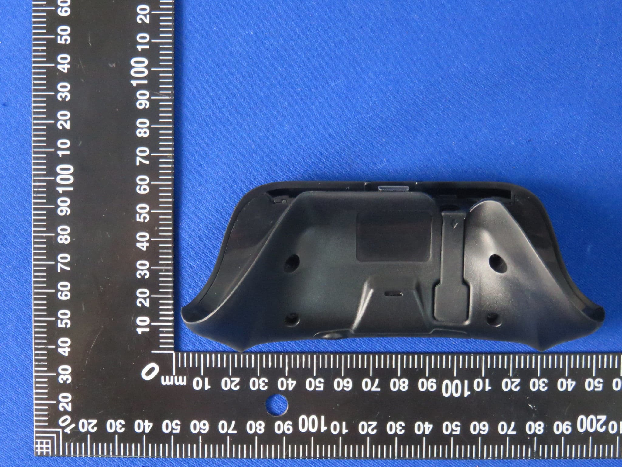
RA3-86125
Jan 27, 2016TYPE PAD
Equipment Class
DXT - Part 15 Low Power Transceiver, Rx Verified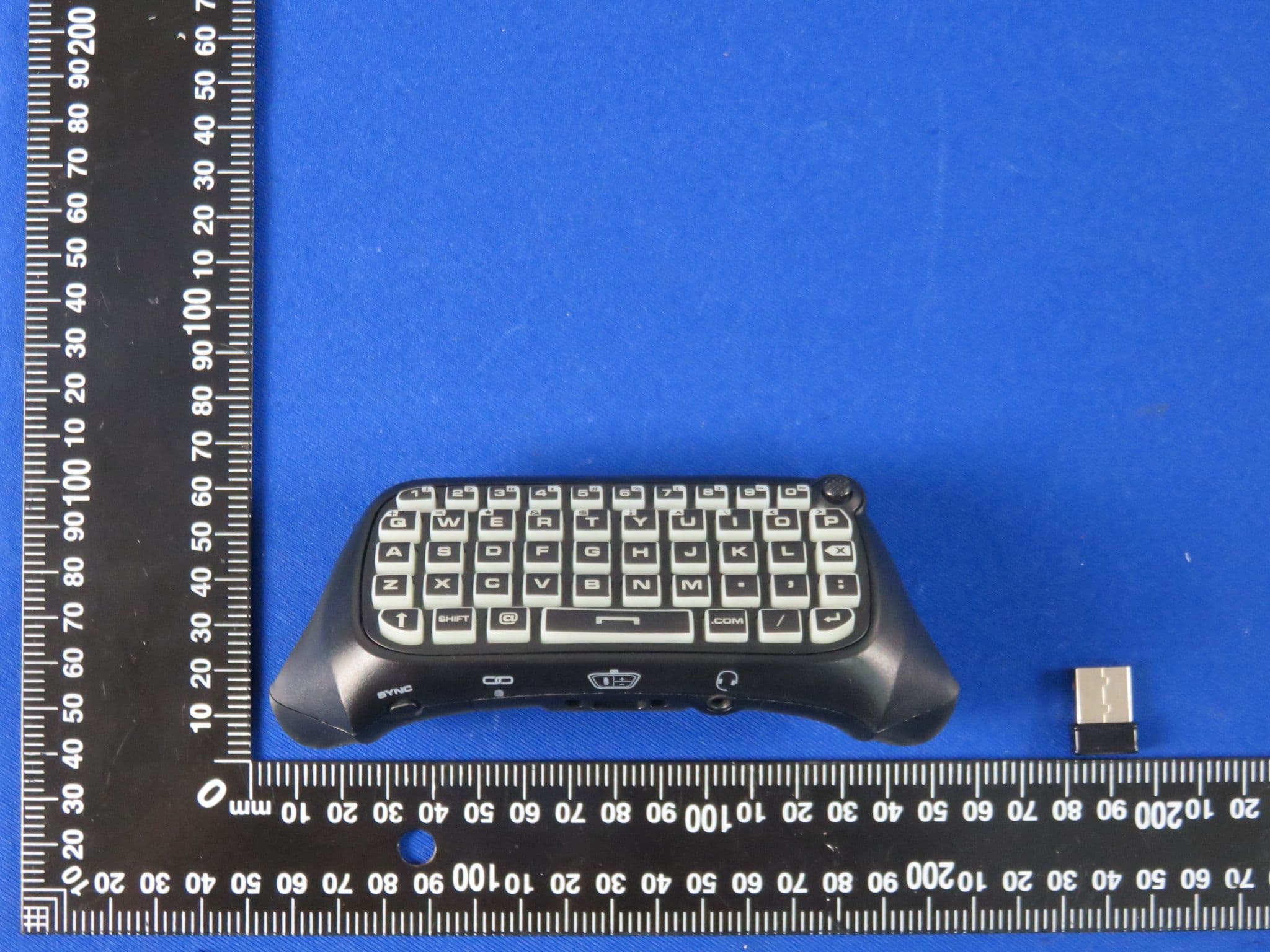
RA386125
Sep 23, 2015TYPE PAD
Equipment Class
DXT - Part 15 Low Power Transceiver, Rx Verified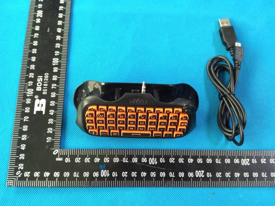
RA383222
Jul 01, 2015TYPE PAD
Equipment Class
DSS - Part 15 Spread Spectrum Transmitter
RA3-87161
Feb 17, 2013Bluetooth Controller Pro Commander
Equipment Class
DSS - Part 15 Spread Spectrum Transmitter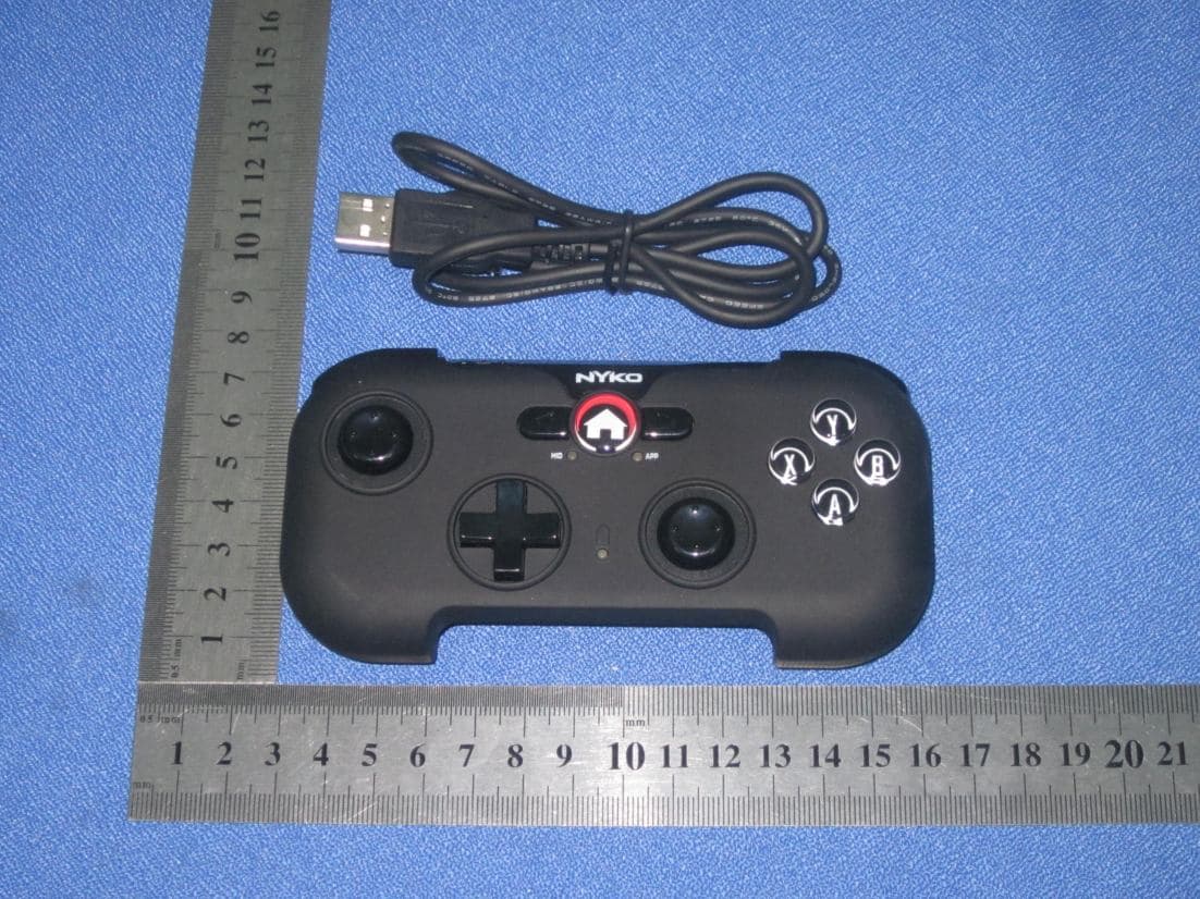
RA3-80691
Nov 27, 2012PLAYPAD
Equipment Class
DXX - Part 15 Low Power Communication Device Transmitter