RA8-BC010Bluetooth Speakerphone
Sunitec Enterprise Co., Ltd.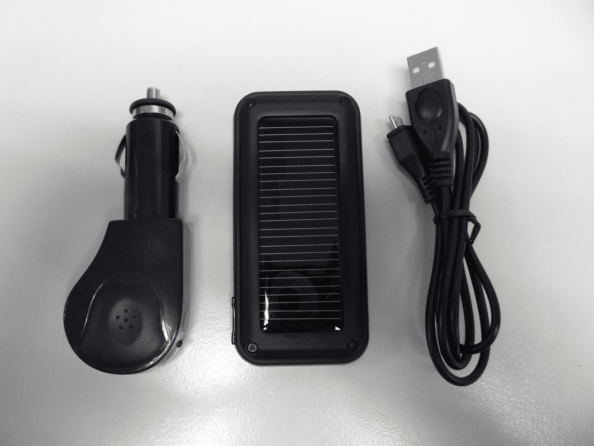
Click to zoom
Application Details
- Equipment Class
- DSS - Part 15 Spread Spectrum Transmitter
- Date of Grant
- Apr 20, 2010
- Application Purpose
- Original Equipment
- Date of Application
- Apr 20, 2010
- Equipment Note
- Bluetooth Speakerphone
- Frequency Range
- 2402.00000000 - 2480.00000000
- Company
- Sunitec Enterprise Co., Ltd.
- Country
- Taiwan
Documents & Files
Document Text
Text extracted from the exhibit documents filed with the FCC. Open a document above to read the original.
Users Manual
13 2 5 4 7 6 1. About Bluetooth Speakerphone This versatile Bluetooth speakerphone is specially designed for the user to enjoy the convenience and freedom of wireless communication. This truly handsfree speakerphone has many applications in the home, office, or car with any wireless Bluetooth compatible technologies. It has an advanced built-in microphone with Digital Sound Processor (DSP) solution for echo cancellation and noise suppression that gives you impeccable full duplex sound quality. 2. About Bluetooth Technology Bluetooth wireless technology is set to revolutionise personal connectivity by providing freedom from wired connections - enabling links and connectivity between notebook/laptop, mobile phones, portable handheld devices and other Bluetooth enabled devices within 10 metres. Utilising global sound and digital data 2.4GHz ISM transmission, it facilitates global communication in a way you have never dreamed of! 3. Getting to Know Your Bluetooth Speakerphone To use your Bluetooth speakerphone, please follow these simple steps: (1) C h a r g e yo u r s p e a k e r p h o n e. Pr i o r t o u s i n g t h e s p e a k e r p h o n e, i t i s recommended to charge the battery fully for the first time. Normal full charge time is 2 hrs. (approx.) (2) Place your speakerphone and a Bluetooth-enabled device within 1 metre for pairing. (3) Ensure your speakerphone and Bluetooth-enabled device is placed within 10 metres during operation to ensure connectivity. (Obstructions could cause shorter sensing distances.) 4. Appearance and Function (1) Speaker (2) Microphone (3) LED (4) Charging Socket (Micro 5-pin USB) (5) MFB Button (Multi-Function Button) (6) Volume Increase (V+) talk time and the standby time) will be extended continuously without any additional charge required by the car charger. WARNING: Do not attempt to charge the speakerphone with any charger other than the one provided. Using another charger may damage or destroy the speakerphone. 7. Turning ON/OFF the Speakerphone Power ON: When the speakerphone is in OFF mode, press and hold the “MFB” for 3 seconds until you hear a short beep. The flashing blue LED light indicator comes on, and then the speakerphone will automatically connect to the mobile phone which has been paired already. Power OFF: Speakerphone is under standby mode, press and hold the “MFB” button for 3 seconds until you hear a short beep. The flashing red LED light indication goes off. 8. Pairing Prior to using the speakerphone for the first time, you must pair it with a Bluetooth-enabled device. The steps below describe pairing instructions for a typical Bluetooth-enabled mobile phone. (1) Place the speakerphone and mobile phone no more than 1 metre apart. (2) Ensure the speakerphone is in the OFF mode. (3) Press and hold the “MFB” button for 5 seconds until the LED light flashes red and blue alternatively, indicating it is now ready for pairing. (4) Activate the Bluetooth function on your mobile phone and search for accessible Bluetooth devices, referring to your mobile phone user guide for details if required. (5) Select “BT Speaker” from the list. (6) E n t e r t h e p re - p ro g r a m m e d c o d e “ 0 0 0 0 ” a n d p re s s “O K ” t o p a i r t h e speakerphone and the mobile phone. When pairing is completed, the blue and red LED light will stop flashing, the speakerphone is in the standby mode with the blue LED light flashing every 3 seconds. (7) Press “Return” to go back to your mobile phone’s main menu. Place the mobile phone and the speakerphone within 10 metres sensing distance. You should now be able to make and receive calls using your speakerphone. Note: If the pairing cannot be completed within 2 minutes after the pairing mode is activated, the speakerphone will power OFF automatically. Please repeat the steps above to pair the speakerphone and mobile phone again. 9. Connection/Link between Speakerphone and Mobile Phone After pairing is completed, the speakerphone is always in standby mode. Before you place or answer a call, if the headset icon is not shown on the mobile phone screen, please follow the steps below to activate the Bluetooth connection/link through your mobile phone or speakerphone until the headset icon is on the screen. (1) On phone: Select the “BT Speaker” from the paired list on your phone screen. (2) On speakerphone: Short press “MFB” and select “Accept” on the phone screen to accept connection. 10. Disconnection between Speakerphone and Mobile Phone When you need to connect your speakerphone with another Bluetooth-enabled mobile phone, follow the steps below to disconnect the speakerphone with the pre-paired mobile phone. (1) Power OFF the speakerphone. (2) Select “Disconnecting” on the Bluetooth device list of your mobile phone to remove the connection. Note: When losing the connection/link, the speakerphone will automatically power OFF within 15 minutes. The blue LED light will flash twice every 3 seconds when the speakerphone is not connected with your mobile phone. 11. Using the Speakerphone (1) Answering a Call When receiving a phone call, press the “MFB” button once to answer the call. (2) Ending a Call Press the “MFB” button once to end a call. (3) Reject a Call When you hear the ringing tone, press and hold the “MFB” button for 3 seconds to reject the call. (4) Voice Dial If your mobile phone has voice dialing enabled, in standby mode, press the “MFB” button once and say the voice tag after you hear a beep. Note: Please make sure to record voice tag into the mobile phone before When power on the speakerphone, it will automatically search and connect the last 2 mobile phones that have been connected before. (4) Reject the Second mobile phone Call When receiving a second call, press and hold the “MFB” button for 3 seconds to reject the second mobile phone call. (5) Answer the Second mobile phone Call When receiving a second call, press “MFB” button once to end the first mobile phone call and answer the second mobile pho…
Text truncated - open the document above for the full version.
Cover Letter(s)
SUNITEC ENTERPRISE CO., LTD. Statement We Sunitec LTD hereby state that BC962 and BC962S are identical in interior structure, electrical circuits. Only different model name and solar battery . Confirmed by: Name in full: liyuanshun Authorized signature: Position: manager Date: 2010-03-10 Company stamp:
External Photos
Page 1 of 2 External Photo Report No.: 17015434 001 Photo 1 Photo 2 Page 2 of 2 External Photo Report No.: 17015434 001 Photo 3 Photo 4
ID Label/Location Info
23.5 mm 9.5 mm Sunitec Enterprise CO., Ltd. Bluetooth Speakerphone Model: BC962S Input: 5V 400mA FCC ID: RA8-BC010 Made in China Sunitec Enterprise CO., Ltd.Bluetooth SpeakerphoneModel: BC962SInput: 5V 400mAFCC ID: RA8-BC010Made in China
Internal Photos
Page 1 of 3 Internal Photo Report No.: 17015434 001 Photo 1 Photo 2 Page 2 of 3 Internal Photo Report No.: 17015434 001 Photo 3 Photo 4 Page 3 of 3 Internal Photo Report No.: 17015434 001 Photo 5 Photo 6
Test Report
Produkte Products Prüfbericht - Nr.: Test Report No. 17015434 001 Seite 2 von 93 Page 2 of 93 TEST SUMMARY 5.1.1 ANTENNA REQUIREMENT RESULT: Passed 5.1.2 PEAK OUTPUT POWER RESULT: Passed 5.1.3 20DB BANDWIDTH RESULT: Passed 5.1.4 100KHZ BANDWIDTH OF FREQUENCY BAND EDGE RESULT: Passed 5.1.5 SPURIOUS EMISSION RESULT: Passed 5.1.6 FREQUENCY SEPARATION RESULT: Passed 5.1.7 NUMBER OF HOPPING FREQUENCY RESULT: Passed 5.1.8 TIME OF OCCUPANCY RESULT: Passed 5.1.9 PEAK POWER DENSITY RESULT: Passed 5.1.10 RADIATED EMISSIONS RESULT: Passed Produkte Products Prüfbericht - Nr.: Test Report No. 17015434 001 Seite 3 von 93 Page 3 of 93 Contents 1. GENERAL REMARKS.........................................................................................................4 1.1 COMPLEMENTARY MATERIALS...........................................................................................4 2. TEST SITES.......................................................................................................................4 2.1 TEST FACILITIES...............................................................................................................4 2.2 LIST OF TEST AND MEASUREMENT INSTRUMENTS...............................................................5 2.3 TRACEABILITY..................................................................................................................6 2.4 CALIBRATION....................................................................................................................6 2.5 MEASUREMENT UNCERTAINTY...........................................................................................6 2.6 LOCATION OF ORIGINAL DATA...........................................................................................6 2.7 STATUS OF FACILITY USED FOR TESTING...........................................................................6 3. GENERAL PRODUCT INFORMATION....................................................................................7 3.1 PRODUCT FUNCTION AND INTENDED USE...........................................................................7 3.2 RATINGS AND SYSTEM DETAILS.........................................................................................7 3.3 INDEPENDENT OPERATION MODES.....................................................................................8 3.4 NOISE GENERATING AND NOISE SUPPRESSING PARTS........................................................9 3.5 SUBMITTED DOCUMENTS...................................................................................................9 4. TEST SET-UP AND OPERATION MODES...............................................................................9 4.1 PRINCIPLE OF CONFIGURATION SELECTION........................................................................9 4.2 TEST OPERATION AND TEST SOFTWARE............................................................................9 4.3 SPECIAL ACCESSORIES AND AUXILIARY EQUIPMENT..........................................................9 4.4 COUNTERMEASURES TO ACHIEVE EMC COMPLIANCE.......................................................10 4.5 TEST SETUP DIAGRAM....................................................................................................10 5. TEST RESULTS...............................................................................................................12 5.1 TRANSMITTER REQUIREMENT & TEST SUITES...................................................................12 5.1.1 Antenna Requirement................................................................................................................ 12 5.1.2 Peak Output Power ................................................................................................................... 13 5.1.3 20dB Bandwidth ........................................................................................................................ 16 5.1.4 100kHz Bandwidth of Frequency Band Edge ........................................................................... 19 5.1.5 Spurious Emission ..................................................................................................................... 21 5.1.6 Frequency Separation ............................................................................................................... 69 5.1.7 Number of hopping frequency ................................................................................................... 72 5.1.8 Time of Occupancy.................................................................................................................... 74 5.1.9 Peak Power Density .................................................................................................................. 80 5.1.10 Radiated emissions ............................................................................................................... 83 6. PHOTOGRAPHS OF THE TEST SET-UP..............................................................................90 7. LIST OF TABLES..............................................................................................................93 8. LIST OF PHOTOGRAPHS...................................................................................................93 Produkte Products Prüfbericht - Nr.: Test Report No. 17015434 001 Seite 4 von 93 Page 4 of 93 1. General Remarks 1.1 Complementary Materials None 2. Test Sites 2.1 Test Facilities TÜV Rheinland (Guangdong) Ltd. EMC Laboratory Guangzhou Auto Market, Yuan Gang Section of Guangshan Road, Guangzhou, P.R. China Produkte Products Prüfbericht - Nr.: Test Report No. 17015434 001 Seite 5 von 93 Page 5 of 93 2.2 List of Test and Measurement Instruments Table 1: List of Test and Measurement Equipment Kind of Equipment Manufacturer Type S/N Calibrated until Spurious emission and Radiated emission EMI Test Receiver Rohde & Schwarz ESCI+3 100216 2011+01+17 Spectrum Analyzer Rohde & Schwarz FSP30 100286 2011+01+17 Trilog+Broadband Ante…
Text truncated - open the document above for the full version.
Test Report
Produkte Products Prüfbericht - Nr.: Test Report No. 17015434 001 Seite 51 von 93 Page 51 of 93 Test Graph of Spurious emission of A.3 – Vertical Produkte Products Prüfbericht - Nr.: Test Report No. 17015434 001 Seite 52 von 93 Page 52 of 93 Produkte Products Prüfbericht - Nr.: Test Report No. 17015434 001 Seite 53 von 93 Page 53 of 93 Produkte Products Prüfbericht - Nr.: Test Report No. 17015434 001 Seite 54 von 93 Page 54 of 93 Produkte Products Prüfbericht - Nr.: Test Report No. 17015434 001 Seite 55 von 93 Page 55 of 93 Produkte Products Prüfbericht - Nr.: Test Report No. 17015434 001 Seite 56 von 93 Page 56 of 93 Produkte Products Prüfbericht - Nr.: Test Report No. 17015434 001 Seite 57 von 93 Page 57 of 93 Test Graph of Spurious emission of B – Horizontal Produkte Products Prüfbericht - Nr.: Test Report No. 17015434 001 Seite 58 von 93 Page 58 of 93 Produkte Products Prüfbericht - Nr.: Test Report No. 17015434 001 Seite 59 von 93 Page 59 of 93 Produkte Products Prüfbericht - Nr.: Test Report No. 17015434 001 Seite 60 von 93 Page 60 of 93 Produkte Products Prüfbericht - Nr.: Test Report No. 17015434 001 Seite 61 von 93 Page 61 of 93 Produkte Products Prüfbericht - Nr.: Test Report No. 17015434 001 Seite 62 von 93 Page 62 of 93 Produkte Products Prüfbericht - Nr.: Test Report No. 17015434 001 Seite 63 von 93 Page 63 of 93 Test Graph of Spurious emission of B – Vertical Produkte Products Prüfbericht - Nr.: Test Report No. 17015434 001 Seite 64 von 93 Page 64 of 93 Produkte Products Prüfbericht - Nr.: Test Report No. 17015434 001 Seite 65 von 93 Page 65 of 93 Produkte Products Prüfbericht - Nr.: Test Report No. 17015434 001 Seite 66 von 93 Page 66 of 93 Produkte Products Prüfbericht - Nr.: Test Report No. 17015434 001 Seite 67 von 93 Page 67 of 93 Produkte Products Prüfbericht - Nr.: Test Report No. 17015434 001 Seite 68 von 93 Page 68 of 93 Produkte Products Prüfbericht - Nr.: Test Report No. 17015434 001 Seite 69 von 93 Page 69 of 93 5.1.6 Frequency Separation RESULT: Passed Date of testing : 2010+03+15 Test standard : FCC part 15.247(a)(1) Basic standard : ANSI C63.4: 2003 Limit : ≥ 25kHz or 20dB bandwidth, whichever is greater Kind of test site : Shield room Test setup Test Channel : Low/ Middle/ High Operation Mode : A Ambient temperature : 22°C Relative humidity : 52% Atmospheric pressure : 101 kPa Table 8: Test result of Frequency Separation Channel Channel Frequency (MHz) Measured Channel Separation (MHz) Limit (kHz) Result Low Channel 2402 Adjacency Channel 2403 1 ≥ 25kHz or 20dB bandwidth Pass Mid Channel 2441 Adjacency Channel 2442 1 ≥ 25kHz or 20dB bandwidth Pass High Channel 2480 Adjacency Channel 2479 1 ≥ 25kHz or 20dB bandwidth Pass Produkte Products Prüfbericht - Nr.: Test Report No. 17015434 001 Seite 70 von 93 Page 70 of 93 Test Graph of Frequency Separation Low Channel A PS Ref 10 dBmAtt 25 dB * 500 kHz/Center 2.403 GHzSpan 5 MHz * RBW 100 kHz VBW 300 kHz SWT 2.5 ms 1 PK VIEW 90 80 70 60 50 40 30 20 10 0 10 1 Marker 1 [T1 ] 4.82 dB m 2.402020000 GHz 2 Delta 2 [T1 ] 0.01 dB 1.000000000 MHz 3 Delta 3 [T1 ] 0.01 dB 2.000000000 MHz Date: 15.MAR.2010 14:48:58 Middle Channel A PS Ref 10 dBmAtt 25 dB * 500 kHz/Center 2.441 GHzSpan 5 MHz * RBW 100 kHz VBW 300 kHz SWT 2.5 ms 1 PK VIEW 90 80 70 60 50 40 30 20 10 0 10 1 Marker 1 [T1 ] 4.96 dB m 2.441030000 GHz 2 Delta 2 [T1 ] 0.00 dB 1.000000000 MHz 3 Delta 3 [T1 ] 0.02 dB 1.000000000 MHz Date: 15.MAR.2010 14:52:19 Produkte Products Prüfbericht - Nr.: Test Report No. 17015434 001 Seite 71 von 93 Page 71 of 93 High Channel A PS Ref 10 dBmAtt 25 dB * 500 kHz/Center 2.479 GHzSpan 5 MHz * RBW 100 kHz VBW 300 kHz SWT 2.5 ms 1 PK VIEW 90 80 70 60 50 40 30 20 10 0 10 1 Marker 1 [T1 ] 4.75 dB m 2.480020000 GHz 2 Delta 2 [T1 ] 0.01 dB 1.000000000 MHz 3 Delta 3 [T1 ] 0.01 dB 2.000000000 MHz Date: 15.MAR.2010 14:54:54 Produkte Products Prüfbericht - Nr.: Test Report No. 17015434 001 Seite 72 von 93 Page 72 of 93 5.1.7 Number of hopping frequency RESULT: Passed Date of testing : 2010+03+15 Test standard : FCC part 15.247(a)(1)(iii) Basic standard : ANSI C63.4: 2003 Limits : ≥ 15 non+overlapping channels Kind of test site : Shield room Test setup Test Channel : Low/ Middle/ High Operation Mode : A Ambient temperature : 22°C Relative humidity : 52% Atmospheric pressure : 101 kPa Table 9: Test result of Number of hopping frequency Frequency Range Measured Quantity of Hopping Channel Limit Result 2400 to 2483.5 MHz 79 ≥15 Pass Produkte Products Prüfbericht - Nr.: Test Report No. 17015434 001 Seite 73 von 93 Page 73 of 93 Test Graph of Number of hopping frequency A PS Ref 10 dBmAtt 25 dB * 4.1 MHz/Start 2.4 GHzStop 2.441 GHz * RBW 100 kHz VBW 300 kHz SWT 5 ms 1 PK VIEW 90 80 70 60 50 40 30 20 10 0 10 1 Marker 1 [T1 ] 4.89 dB m 2.401968000 GHz 2 Delta 2 [T1 ] 0.20 dB 38.130000000 MHz Date: 15.MAR.2010 15:03:16 Ref 10 dBmAtt 25 dB * A PS 4.25 MHz/Start 2.441 GHzStop 2.4835 GHz * RBW 100 kHz VBW 300 kHz SWT 5 ms 1 PK VIEW 90 80 70 60 50 40 30 20 10 0 10 1 Marker 1 [T1 ] 4.47 dB m 2.441000000 GHz 2 Delta 2 [T1 ] 0.35 dB 39.015000000 MHz Date: 15.MAR.2010 15:06:17 Produkte Products Prüfbericht - Nr.: Test Report No. 17015434 001 Seite 74 von 93 Page 74 of 93 5.1.8 Time of Occupancy RESULT: Passed Date of testing : 2010+03+15 Test standard : FCC part 15.247(a)(1)(iii) Basic standard : ANSI C63.4: 2003 Limits : 0.4s Kind of test site : Shield room Test setup Test Channel : Low/ Middle/ High Operation Mode : A Ambient temperature : 22°C Relative humidity : 52% Atmospheric pressure : 101 kPa Table 10: Test result of Time of Occupancy Channel Data Mode Pulse width (ms) Measured Dwell time (s) Limit (s) Result DH1 0.395 0.126 0.4 Pass DH3 1.305 0.209 0.4 Pass Low Channel DH5 2.885 0.308 0.4 Pass DH1 0.395 0.126 0.4 Pass DH3 1.305 0.209 0.4 Pass Mid Channel DH5 2.905 0.310 0.4 Pass DH1 0.395 0.126 0.4 Pass DH3 1.3 0.208 0.4 Pass High Channel DH5 2.89 0.308 0.4 Pass Note: Dwell time = Pulse width x (Hopping rate / Number of channels) x Period Period = 0.4 (…
Text truncated - open the document above for the full version.
Test Setup Photos
Produkte Products Prüfbericht - Nr.: Test Report No. 17015434 001 Seite 90 von 93 Page 90 of 93 6. Photographs of the Test Set-Up Photograph 1: Set-up for Spurious Emissions (9kHz-30MHz) Photograph 2: Set-up for Spurious Emissions (30MHz-1GHz) Produkte Products Prüfbericht - Nr.: Test Report No. 17015434 001 Seite 91 von 93 Page 91 of 93 Photograph 3: Set-up for Spurious Emissions (1GHz-18GHz) Photograph 4: Set-up for Spurious Emissions (18GHz-26GHz) Produkte Products Prüfbericht - Nr.: Test Report No. 17015434 001 Seite 92 von 93 Page 92 of 93 Photograph 5: Set-up for Radiated Emissions
Contact Information
Applicant
Tom Chien(General Manager)
Test Firm
TUV Rheinland (GuangDong) Ltd.Yuxin Huang
Technical Specifications
| # | Rule Parts | Frequency Range | Power Output |
|---|---|---|---|
| 1 | 15C | 2.40 GHz - 2.48 GHz | 3.08 mW |
Other Applications from Sunitec Enterprise Co., Ltd.
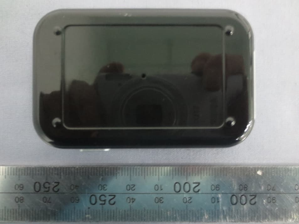
RA8-BA530
May 19, 2014Bluetooth Audio Transmitter
Equipment Class
DSS - Part 15 Spread Spectrum Transmitter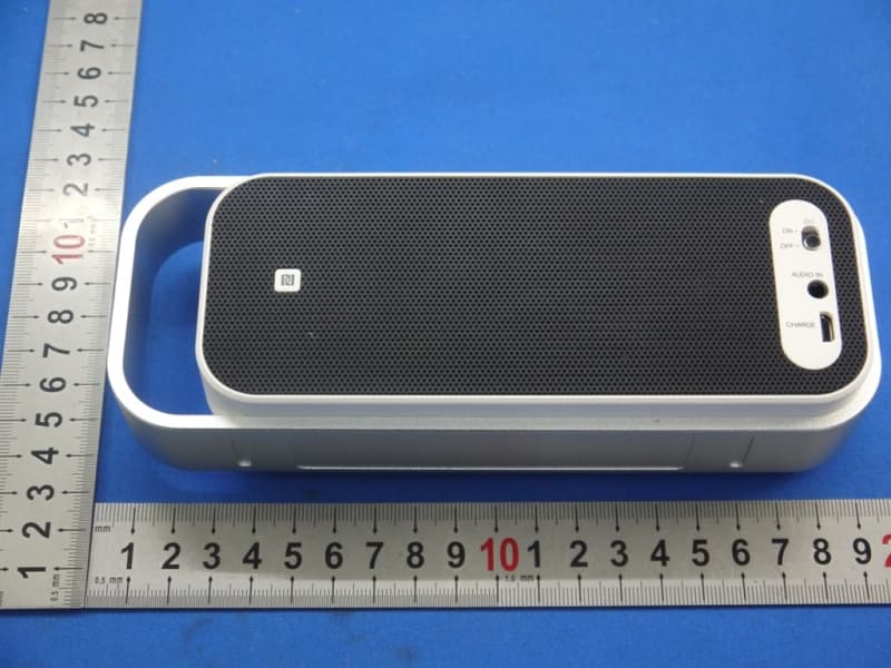
RA8-SPABT2
Mar 25, 2014BLUETOOTH STEREO SPEAKER
Equipment Class
DSS - Part 15 Spread Spectrum Transmitter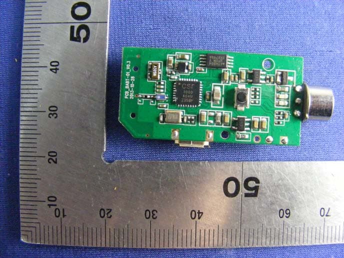
RA8-BH006
Mar 17, 2014Bluetooth Alcohol Breath Tester
Equipment Class
DTS - Digital Transmission System
RA8-BS006
Mar 05, 2014Bluetooth Speaker
Equipment Class
DTS - Digital Transmission System
RA8-BH005
Jan 01, 2014Bluetooth Headset
Equipment Class
DSS - Part 15 Spread Spectrum Transmitter