RAD312Module
TCT Mobile Limited
Click to zoom
Application Details
- Equipment Class
- PCB - PCS Licensed Transmitter
- Date of Grant
- Feb 24, 2013
- Application Purpose
- Original Equipment
- Date of Application
- Feb 24, 2013
- Equipment Note
- Module
- Frequency Range
- 1852.40000000 - 1907.60000000
- Company
- TCT Mobile Limited
- Country
- China
Documents & Files
Document Text
Text extracted from the exhibit documents filed with the FCC. Open a document above to read the original.
Users Manual
User Manual This module is limited to OEM Installation only. Welcome! This manual brief is the profile of your modem, it is a removable device for wireless internet access and data service. 1. Getting to Know Your Modem A. SIM/USIM Card B. Antenna C. PCIE Interface 2. How to start your modem 3. Your modem key features a) Up to 21Mbps DL and 5.76Mbps UL b) Rx Diversity c) SMS d) Phonebook e) Support Android 2.2/2.3/3.0/4.0 4. Safety and Use We recommend that you read this chapter carefully before using the modem. The manufacturer disclaims any liability for damage, which may result as a consequence of improper use of the modem or of use contrary to the instructions contained herein. Traffic Safety When driving, do not use the modem When switched on, the modem emits electromagnetic waves that can interfere with the vehicle’s electronic systems such as ABS anti‐lock brakes or airbags. To ensure that there is no problem, do not place Insert SIM card Into modem Power off your Tablet Plug the modem into your Tablet Power on your Tablet your tablet with the modem on top of the dashboard or within an airbag deployment area. Check with your car dealer or the car manufacturer to make sure that the dashboard is adequately shielded from modem RF energy. Conditions of Use Switch the modem off before boarding an aircraft. Switch the modem off when you are in health care facilities, except in designated areas. As with many other types of equipment now in regular use, the modem can interfere with other electrical or electronic devices, or equipment‐using radio frequencies. Switch the modem off when you are near gas or flammable liquids. Strictly obey all signs and instructions posted in a fuel depot, petrol station, chemical plant, or in any potentially explosive atmosphere. When the modem is switched on, it should be kept at least 15 cm from any medical device such as a pacemaker, a hearing aid or insulin pump, etc. Do not let children use the modem without supervision. When replacing the cover, please note that the modem may contain substances that could create an allergic reaction. Always handle the modem with care and keep it in a clean and dust‐free place. Do not allow the modem to be exposed to adverse weather or environmental conditions (moisture, humidity, rain, infiltration of liquids, dust, sea air, etc). The manufacturer’s recommended operating temperature range is ‐10°C to +50°C. Do not open, dismantle or attempt to repair the modem yourself. Do not drop, throw or bend the modem. Do not paint it. 5. Host Information Host manufacturer is: TCT Mobile Limited Host Brand name is: ALCATEL; Host model number is: One Touch T70. WEEE Approval The modem is in compliance with the essential requirements and other relevant provisions of the Waste Electrical and Electronic Equipment Directive 2002/96/EC (WEEE Directive). They will then be recycled, preventing substances being disposed of in the environment, so that their components can be reused. In European Union countries: This symbol on device means that these products must be taken to collection points at the end of their life: ‐ Municipal waste disposal centres with specific bins for these items of equipment ‐ Collection bins at points of sale. These collection points are accessible free of charge. All products with this sign must be brought to these collection points. In non European Union jurisdictions: Items of equipment with this symbol are not to be thrown into ordinary bins if your jurisdiction or your region has suitable recycling and collection facilities; instead they are to be taken to collection points for them to be recycled. RoHs Approval The modem is in compliance with the restriction of the use of certain hazardous substances in electrical and electronic equipment Directive 2002/95/EC (RoHs Directive). Certification Federal Communications Commission Notice (United States): The end product with an embedded M70 Module may also need to pass the FCC Part 15 unintentional emission testing requirements and be properly authorized per FCC Part 15. This device complies with Part 15 of the FCC Rules. Operation is subject to the following two conditions: (1) this device may not cause harmful interference, and (2) this device must accept any interference received, including interference that may cause undesired operation. Changes or modifications made to this equipment not expressly approved by TCL may void the FCC authorization to operate this equipment. Please be noticed following information and instructions should be placed in the end‐user’s operating manual The M70 Module has been granted as limited modular approval , which was designed to be fixed to specified host only in this manual. 1. Separate approval is required for all other operating configurations, including portable configurations with respect to 2.1093 and different antenna configurations. 2. A label must be affixed to the outside of the end product into which the M70 module is incorporated, with a statement similar to the following: This device contains FCC ID: RAD312. 3. This module is to be installed only in specified host as specified in this manual only. The host with this LMA module has been tested against this SAR limit. The highest SAR value reported for properly worn on the body is 1.176W/kg. This device was tested for typical body‐worn operations with the back of the host which is 5mm distance with the body. To maintain compliance with FCC RF exposure requirements, use accessories that it was tested directly with the user's body and the back of the host. The use of belt clips, holsters and similar accessories should not contain metallic components in its assembly. The use of accessories that do not satisfy these requirements may not comply with FCC RF exposure requirements, and should be avoided. 4. Separate approval is required for all other operating configurations, including portable configurations with respect to FCC Part 2.1093 and diffe…
Text truncated - open the document above for the full version.
Block Diagram
4/F, South Building,No.2966, Jinke Road, Zhangjiang High-Tech Park, Pudong, Shanghai, 201203, P.R.China, TEL: +86(0)21 61460666 FAX: +86(0)21 61460600 Request for Modular Approval FCC ID: RAD312 Item Requirements EUT 1 Have its own RF shielding Yes. But this 3G module is designed for the specific host only. The host manufacturer is: TCT Mobile Limited Host Brand name is: ALCATEL; Host model number is: One Touch T70. Host FCC ID: RAD310 2 Have buffered modulation/data inputs (if such inputs are provided) All inputs to the modules are buffered through logic and microprocessor inputs(Quaclcomm RTR6285). 3 Have its own power supply regulation Module has no own power supply. It must be connected with host while working. The host PMU is TPS659102A1RSLR 4 Meet the antenna requirements of section 15.203 The device contains a PIFA antenna, and the maximum antenna gain is 0.3dBi for GSM/UMTS850, and GSM/UMTS1900 is 1.2dBi. 5 Demonstrate compliance in a stand‐alone configuration Device is tested in a specific host as indicated in item 1. 6 The licensed module must have a FCC ID label on the module itself. That FCC ID label must be visible through a window on the final device or it must be visible when an access panel, door or cover is easily removed. If not, a second label must be placed on the outside of the final device. FCC ID label format will be included in the filling. Host ID label will be displayed on the host system. Host FCC ID: RAD310; 3G Module FCC ID: RAD312” 7 The module must comply with all Please refer to “User Manual” Exhibit specific rules applicable to the transmitter. The grantee must provide comprehensive instructions to explain compliance requirements. 8 The module must comply with RF exposure requirements. See FCC Rules. Spread Spectrum transmitters must comply with RF exposure limits in 15.247. This module is designed for specific host. Please refer to SAR report exhibit. Thank you for your attention to this matter. Yours Sincerely, Zhizhou Gong Project Manager
Cover Letter(s)
Date: Jan. 21, 2013 To: Federal Communications Commission, Authorization & Evaluation Division, 7435 Oakland Mills Road, Columbia, MD 21046 To Whom It May Concern: The TCT Mobile Limited. ,the undersigned, hereby authorizes Mr. Wu Xuewen from Shenzhen Morlab Communications Technology Co., Ltd.,, to act on the behalf of the TCT Mobile Limited. solely in matters relating to the application for an FCC equipment authorization for FCC ID # RAD312 including the signing of documents in connection with this Application. Necessary acts carried out by TCT Mobile Limited.on our behalf of the TCT Mobile Limited.in connection with the Application shall have the same effect as acts of the TCT Mobile Limited.. The TCT Mobile Limited.also hereby certify that no party to this application is subject to a denial of benefits, including FCC benefits, pursuant to Section 5301 of the Anti-Drug Abuse Act of 1988, 21 U.S.C. 853(a). Yours Sincerely, Zhizhou Gong Project Manager
Cover Letter(s)
Date: Jan 21, 2013 To: Federal Communications Commission, Authorization & Evaluation Division, 7435 Oakland Mills Road, Columbia, MD 21046 Re: TCT Mobile Limited FCC ID: RAD312 FCC Part 15C Certification Confidentiality Request Gentlemen: This letter is to comply with 47 CFR 0.457& 0.459 pertaining to confidentiality material. TCT Mobile Limited requests that the following documents regarding this submission for FCC ID: RAD312 be kept confidential: Exhibit Type File Name Block Diagram CONF APPENDIX RAD312_Block Diagram.pdf Schematics CONF APPENDIX RAD312_Schematics.pdf Operational Description CONF APPENDIX RAD312_Operational Description.pdf Part list CONF APPENDIX RAD312_BOM.pdf Tune-Up-Procedure CONF APPENDIX RAD312_Tune up procedure.pdf Those documents contain detailed system and equipment description and related information about the product which TCT Mobile Limited considers to be confidential proprietary, a custom design and , otherwise, not releasable to the general public. Since this design is a basis form which future technological products will evolve, TCT Mobile Limited considers this information would be of benefit to its competitors, and that the disclosure of the information in these documents would give competitors an unfair advantage in the market. Yours Sincerely, Zhizhou Gong Project Manager
External Photos
External Photos 1. EUT front view 2. EUT rear view 3. Side View Host External Photos Host manufacturer is: TCT Mobile Limited Host Brand name is: ALCATEL; Host model number is: One Touch T70; Host FCC ID: RAD310 1. EUT full view with accessories 2. EUT front view 3. EUT rear view 4. EUT left side view 5. EUT right side view 6. EUT side view 7. EUT side view
ID Label/Location Info
FCC ID: RAD312 Label FCC ID Size: 25*15mm Label Location FCC ID
Internal Photos
Internal Photos 1. EUT front view without shielding 2. EUT rear view without shielding 3. GSM/WCDMA chip view 4. GSM/WCDMA antenna view Host Internal Photos Host manufacturer is: TCT Mobile Limited Host Brand name is: ALCATEL; Host model number is: One Touch T70; Host FCC ID: RAD310 1. EUT uncover view 2. Mainboard front view with shielding 3. Mainboard rear view with shielding 4. Mainboard front view without shielding 5. Mainboard rear view without shielding 6. BT/WIFI chip view 7. BT/WIFI antenna view 8. LCD screen view
RF Exposure Info
SZ12120200S01 Page 2 of 88 DIRECTORY DIRECTORY....................................................................................................................................2 TESTING LABORATORY.............................................................................................................4 1.1. Identification of the Responsible Testing Laboratory................................................................. 4 1.2. Identification of the Responsible Testing Location.....................................................................4 1.3. Accreditation Certificate..............................................................................................................4 1.4. List of Test Equipments...............................................................................................................4 2. TECHNICAL INFORMATION..................................................................................................5 2.1. Identification of Applicant...........................................................................................................5 2.2. Identification of Manufacturer.....................................................................................................5 2.3. Equipment Under Test (EUT)......................................................................................................5 2.3.1. Photographs of the EUT............................................................................................................5 2.3.2. Identification of all used EUT...................................................................................................5 2.4. Applied Reference Documents.................................................................................................... 6 2.5. Device Category and SAR Limits................................................................................................6 2.6. Test Environment/Conditions......................................................................................................7 3. SPECIFIC ABSORPTION RATE (SAR)...................................................................................8 3.1. Introduction..................................................................................................................................8 3.2. SAR Definition............................................................................................................................ 8 4. SAR MEASUREMENT SETUP..................................................................................................9 4.1. The Measurement System............................................................................................................9 4.2. Probe............................................................................................................................................ 9 4.3. Probe Calibration Process..........................................................................................................11 4.3.1 Dosimetric Assessment Procedure...........................................................................................11 4.3.2 Free Space Assessment Procedure...........................................................................................11 4.3.2 Temperature Assessment Procedure........................................................................................11 4.4. Phantom..................................................................................................................................... 12 4.5. Device Holder............................................................................................................................12 5. TISSUE SIMULATING LIQUIDS........................................................................................... 13 6. UNCERTAINTY ASSESSMENT............................................................................................. 15 6.1. UNCERTAINTY EVALUATION FOR EUT SAR TEST....................................................... 15 6.2. UNCERTAINTY FOR SYSTEM PERFORMANCE CHECK................................................ 16 7. SAR MEASUREMENT EVALUATION................................................................................. 18 SZ12120200S01 Page 3 of 88 7.1. System Setup..............................................................................................................................18 7.2. Validation Results......................................................................................................................19 8. OPERATIONAL CONDITIONS DURING TEST..................................................................20 8.1. Body-worn Configurations........................................................................................................ 20 8.2. Measurement procedure.............................................................................................................20 8.3. Description of interpolation/extrapolation scheme....................................................................21 9.Measurement Of Conducted Peak Output Power..........................................................................22 10. TEST RESULTS LIST.............................................................................................................25 ANNEX A EUT SETUP PHOTOS................................................................................................30 ANNEX B GRAPH TEST RESULTS...........................................................................................33 Change History IssueDateReason for change 1.0Jan. 22, 2013First edition 2.0Jan. 29, 2013Second edition SZ12120200S01 Page 4 of 88 Testing Laboratory 1.1. Identification of the Responsible Testing Laboratory Company Name:Shenzhen Morlab Communications Technology Co., Ltd. Department:Morlab Laboratory Address:FL.1, Building A, FeiYang Science Park, Block 67, BaoAn District Responsible Test Lab Manager:Mr. S…
Text truncated - open the document above for the full version.
Test Report
Report No.: SZ12120200W01 Page 2 of 145 TABLE OF CONTENTS 1. GENERAL INFORMATION .................................................................................................... 3 1.1 EUT Description ......................................................................................................................... 3 1.2 Test Standards and Results ........................................................................................................ 5 1.3 Facilities and Accreditations ...................................................................................................... 6 2. 47 CFR PART 2, PART 22H & 24E REQUIREMENTS ........................................................ 7 2.1 Conducted RF Output Power .................................................................................................... 7 2.2 Peak to Average Radio .............................................................................................................. 15 2.3 99% Occupied Bandwidth ....................................................................................................... 21 2.4 Frequency Stability ................................................................................................................... 41 2.5 Conducted Out of Band Emissions ......................................................................................... 48 2.6 Band Edge ................................................................................................................................. 86 2.7 Transmitter Radiated Power (EIRP/ERP) ........................................................................... 100 2.8 Radiated Out of Band Emissions .......................................................................................... 106 Change History Issue Date Reason for change 1.0 Feb 20, 2013 First edition Report No.: SZ12120200W01 Page 3 of 145 1. GENERAL INFORMATION 1.1 EUT Description EUT Type ............................. : Tablet Serial No. .............................. : (n.a, marked #1 by test site) Hardware Version ................. : V06 Software Version .................. : Applicant .............................. : Manufacturer ........................ : V1.5.8 TCT Mobile Limited 5F, C building, No. 232, Liang Jing Road ZhangJiang High-Tech Park, Pudong Area Shanghai, P.R. China. 201203 TCL COMMUNICATION TECHNOLOGY HOLDINGS LIMITED. 70 Huifeng 4rd,ZhongKai Hi-tech Development District , Huizhou, Guangdong 516006 P.R.China Frequency Range .................. : GSM 850MHz: Tx: 824.20 - 848.80MHz (at intervals of 200kHz); Rx: 869.20 - 893.80MHz (at intervals of 200kHz) GSM 1900MHz: Tx: 1850.20 - 1909.80MHz (at intervals of 200kHz); Rx: 1930.20 - 1989.80MHz (at intervals of 200kHz) WCDMA 850MHz Tx: 826.4 - 846.6MHz (at intervals of 200kHz); Rx: 871.4 - 891.6MHz (at intervals of 200kHz) WCDMA 1900MHz Tx: 1852.4 - 1907.6MHz (at intervals of 200kHz); Rx: 1932.4 - 1987.6MHz (at intervals of 200kHz) Modulation Type................... : GPRS Mode with GMSK Modulation EDGE Mode with 8PSK Modulation WCDMA Mode with QPSK Modulation HSDPA Mode with QPSK Modulation HSUPA Mode with QPSK Modulation HSPA+ Mode with QPSK Modulation Multislot Class ...................... : GPRS: Multislot Class12,EGPRS: Multislot Class12 Antenna Type ........................ : PIFA Antenna Emission Designators ........... : GPRS850:250KGXW,GPRS1900: 1900:248KG7W EGPRS850:246KG7W, EGPRS1900:247KG7W, WCDMA850:4M19F9W,WCDMA1900:4M20F9W HSDPA850:4M21F9W,HSDPA1900:4M20F9W HSUPA850:4M19F9W,HSUPA1900:4M19F9W HSPA+850:4M20F9W,HSPA+1900:4M19F9W Report No.: SZ12120200W01 Page 4 of 145 Note 1: The transmitter (Tx) frequency arrangement of the Cellular 850MHz band used by the EUT can be represented with the formula F(n)=824.2+0.2*(n-128), 128<=n<=251; the lowest, middle, highest channel numbers (ARFCHs) used and tested in this report are separately 128 (824.2MHz), 190 (836.6MHz) and 251 (848.8MHz). Note 2: The transmitter (Tx) frequency arrangement of the PCS 1900MHz band used by the EUT can be represented with the formula F(n)=1850.2+0.2*(n-512), 512<=n<=810; the lowest, middle and highest channel numbers (ARFCHs) used and tested in this report are separately 512 (1850.2MHz), 661 (1880.0MHz) and 810 (1909.8MHz). Note 3: The transmitter (Tx) frequency arrangement of the WCDMA 850MHz band used by the EUT can be represented with the formula F(n)=826.4+0.2*(n-4132), 4132<=n<=4233; the lowest, middle and highest channel numbers (ARFCHs) used and tested in this report are separately 4132 (826.4MHz), 4175(835MHz) and 4233 (846.6MHz). Note 4: The transmitter (Tx) frequency arrangement of the WCDMA 1900MHz band used by the EUT can be represented with the formula F(n)=1852.4+0.2*(n-9262), 9262<=n<=9538; the lowest, middle and highest channel numbers (ARFCHs) used and tested in this report are separately 9262 (1852.4MHz), 9400 (1880MHz) and 9538 (1907.6MHz). Note 5: For a more detailed description, please refer to Specification or User’s Manual supplied by the applicant and/or manufacturer. Report No.: SZ12120200W01 Page 5 of 145 1.2 Test Standards and Results The objective of the report is to perform testing according to 47 CFR Part 2, Part 22 and Part 24 for the EUT FCC ID Certification: No. Identity Document Title 1 47 CFR Part 2 (10-1-09 Edition) Frequency Allocations and Radio Treaty Matters; General Rules and Regulations 2 47 CFR Part 22 (10-1-09 Edition) Public Mobile Services 3 47 CFR Part 24 (10-1-09 Edition) Personal Communications Services Test detailed items/section required by FCC rules and results are as below: No. Section Description Result 1 2.1046 Conducted RF Output Power PASS 2. 24.232(d) Peak to average radio PASS 2 2.1049 22.917 24.238 99% Occupied Bandwidth PASS 3 2.1055 22.355 24.235 Frequency Stability PASS 4 2.1051 2.1057 22.917 24.238 Conducted Out of Band Emissions PASS 5 2.1051 2.1057 22.917 24.238 Band Edge PASS 6 22.913 24.232 Transmitter Radiated Power (EIPR/ERP) PASS 7 2.1053 2.…
Text truncated - open the document above for the full version.
Test Setup Photos
Test Setup Photos 1. Conducted Spurious Emission 2. Radiated Spurious Emission
Contact Information
Applicant
Zhizhou Gong
Test Firm
Shenzhen Morlab Communications Technology Co., LtdIvy zhu
Technical Specifications
| # | Rule Parts | Frequency Range | Power Output | Emission | Tolerance |
|---|---|---|---|---|---|
| 6 | 24E | 1.85 GHz - 1.91 GHz | 178.00 mW | 4M20F9W | 0.02 ppm |
Other Applications from TCT Mobile Limited
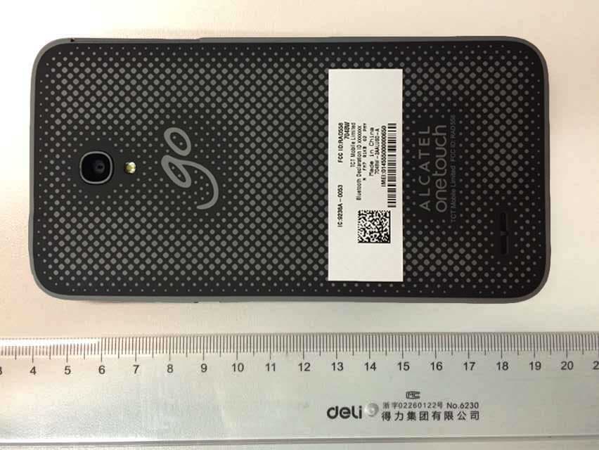
RAD558
Nov 15, 2015HSUPA/HSDPA/UMTS tribands / GSM quadbands/LTE 6-band mobile phone
Equipment Class
JBP - Part 15 Class B Computing Device Peripheral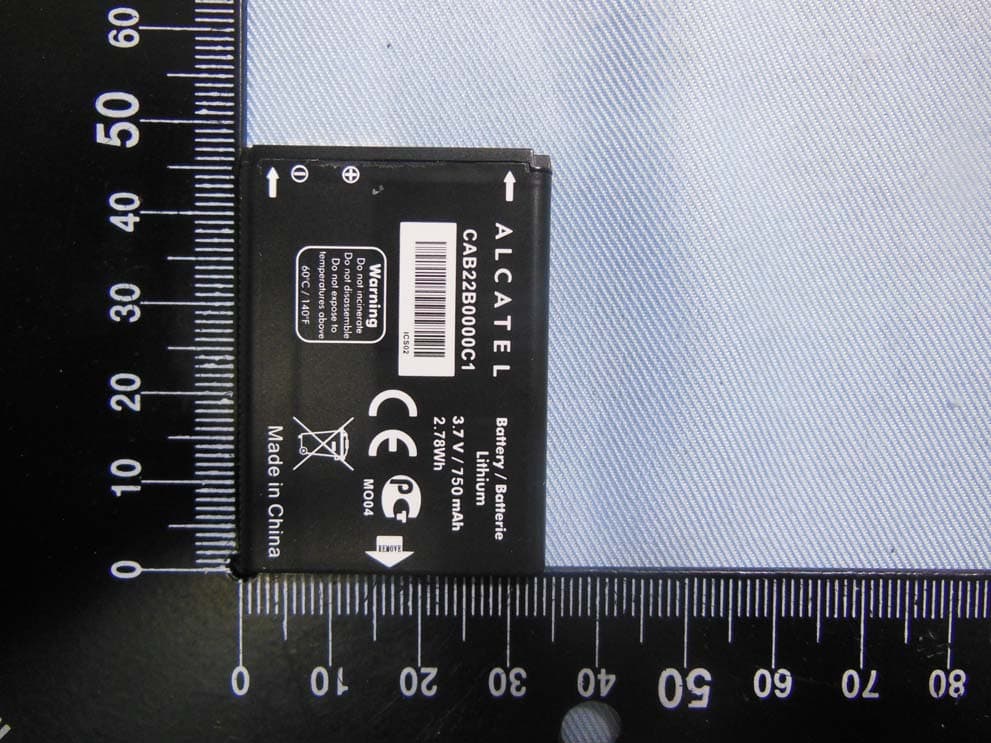
RAD556
Sep 08, 2015CDMA 1X BC0/BC1/BC10 mobile phone
Equipment Class
PCE - PCS Licensed Transmitter held to ear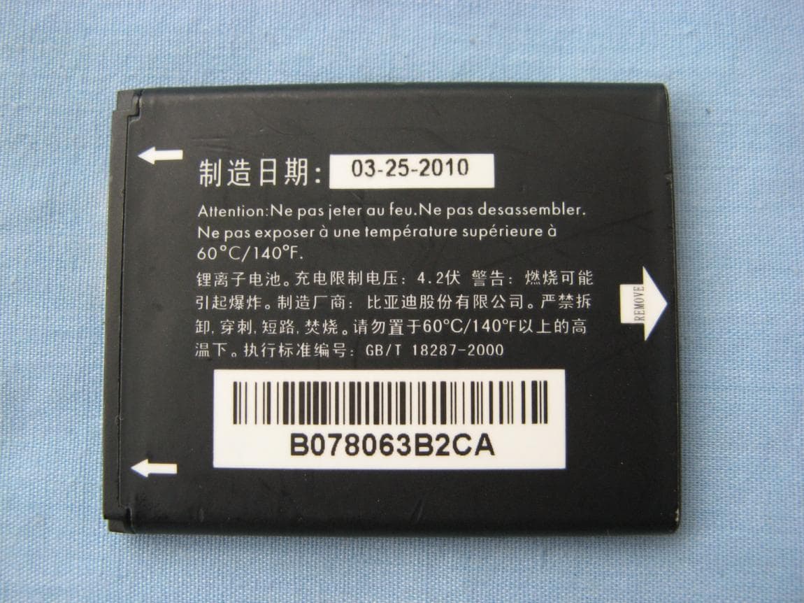
RAD552
Jun 20, 2015GSM Quadband / UMTS Triband mobile phone
Equipment Class
PCE - PCS Licensed Transmitter held to ear
RAD550
Jun 06, 2015HSDPA/HSUPA/HSPA+/UMTS quad band /GSM quad band/LTE 4 band mobile phone
Equipment Class
DSS - Part 15 Spread Spectrum Transmitter
RAD549
May 13, 2015WCDMA tri band / GSM quad band Moblie phone with BT, Wi-Fi functionality.
Equipment Class
DSS - Part 15 Spread Spectrum Transmitter