RAD320GSM quad bands mobile phone
TCT Mobile Limited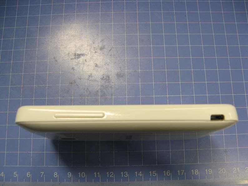
Click to zoom
Application Details
- Equipment Class
- DSS - Part 15 Spread Spectrum Transmitter
- Date of Grant
- Mar 12, 2013
- Application Purpose
- Original Equipment
- Date of Application
- Mar 11, 2013
- Equipment Note
- GSM quad bands mobile phone
- Frequency Range
- 2402.00000000 - 2480.00000000
- Company
- TCT Mobile Limited
- Country
- China
Documents & Files
Document Text
Text extracted from the exhibit documents filed with the FCC. Open a document above to read the original.
Users Manual
12 English - CJB26R0ALAAN Quick Start Guide For more information about how to use the phone, please go to www.alcatelonetouch.com to download complete user manual. Also on our website you can find helpful FAQs, realize software upgrade, etc. Your mobile 1 .................. Keys and connectors1.1 Proximity sensor Touch screen LED light Back key Home key Menu key Headset connector Power key micro-USB connector Volume up Volume down 4005D IP4464_4005D_QG_Eng_USA_09_130222.indd 1-2IP4464_4005D_QG_Eng_USA_09_130222.indd 1-22013-2-22 11:55:572013-2-22 11:55:57 34 Camera On Home screen, press to quickly access • Settings menu or Notification panel; to launch quick search; to manage applications; to customize your Home screen by adding applications or changing wallpaper. On other screens, press to view options list.• Press: Return to the Home screen or back to the central Home screen if it is extended. Press and hold: Enter the recently used applications list. Go back to the previous menu or screen. Press: Lock the screen. Light up the screen. Press and hold: When phone is off, power on the phone. When phone is on, enter Phone options: Silent mode, Airplane mode, Power off. Press to adjust the Volume (in call/media playing mode) Getting started1.2 Set-up1.2.1 Removing or installing the back cover Inserting or removing the SIM card You must insert your SIM card to make phone calls. Please power off your phone and remove battery before inserting or removing the SIM card. Place the SIM card with the chip facing downwards and slide it into its housing. Make sure that it is correctly inserted. To remove the card, press and slide it out. Installing or removing the battery Insert and click the battery into place, then close the phone cover.• Unclip the cover, then remove the battery.• IP4464_4005D_QG_Eng_USA_09_130222.indd 3-4IP4464_4005D_QG_Eng_USA_09_130222.indd 3-42013-2-22 11:55:582013-2-22 11:55:58 56 Installing and removing the microSD card To release the microSD card holder, slide it in the direction of the arrow and lift it. Then insert the microSD card with the golden contact downward. Finally, turn down the microSD holder and slide it in the opposite direction to lock it. Charging the battery Connect the battery charger to your phone and outlet respectively. To reduce power consumption and energy waste, when battery is fully charged, disconnect your charger from the plug; switch off Wi-Fi, GPS, Bluetooth or background-running applications when not in use; reduce the backlight time, etc. Power on your phone1.2.2 Hold down the Power key until the phone powers on. It will take some seconds before the screen lights up. Set up your phone for the first time The first time you power on the phone, you are prompted to set up your phone in multiple ways: language, input method, mobile data connection, account setup and synchronization, system update, etc. You are required to sign into your Google account to synchronize email, contacts, calendar and other Google applications (1) . Enter your user name and password, then touch • Sign in. If you forget your password, you can go to http://www.google.com/ to retrieve it. If you don’t own a Google Account, you are prompted to create one by touching Create. Read the setup information on the screen• . Mark/Unmark the check box to choose whether you want to take • advantage of Google's location service, then touch Next. Mark/Unmark the check box to choose whether you want to back • up data with your Google account, then touch Next. Touch • Finish setup. This initial set up can be skipped and enabled via Settings\Accounts & sync. In power on screen without SIM card inserted, you can also connect to a Wi-Fi network to sign into your Google account and to use some features. Power off your phone1.2.3 Hold down the Power key until the phone options appear, select Power off. (1) Application availability depends on country and operator. IP4464_4005D_QG_Eng_USA_09_130222.indd 5-6IP4464_4005D_QG_Eng_USA_09_130222.indd 5-62013-2-22 11:55:582013-2-22 11:55:58 78 Home screen1.3 You can bring all the items (applications, shortcuts, folders and widgets) you love or use most frequently to your home screen for quick access. Press Home key to switch to Home screen. Status bar Status/Notification indicators • Touch and Drag down to open • notification panel. Application tab Touch to open applications list. Press and hold to display thumbnails. Touch to access Messaging Touch to place a call/access Call log if you have missed call(s). Search bar Touch n to enter Search options: All, Web, Apps, Contacts, etc. Touch o to enter voice search screen. Touch an icon to open an application, folder, etc. o n Home screen is provided in an extended format to allow more space for adding applications, shortcuts etc. Slide the Home screen horizontally left and right to get a complete view of the Home screen. Small dots at the lower left and right of the screen indicate which screen you are viewing. Using the touchscreen1.3.1 Touch To access an application, touch it with your finger. Touch and Hold To enter the available options for an item, touch and hold the item. For example, select a contact in Contacts, touch and hold this contact, options list will then appear on screen. Drag Place your finger on the screen to drag an object to another location. Slide/Swipe Slide the screen to scroll up and down the applications, images, web pages... at your convenience. Flick Similar to swiping, but flicking makes it move quicker. Pinch/Spread Place your fingers of one hand on the screen surface and draw them apart or together to scale an element on the screen. Rotate Automatically change the screen orientation from portrait to landscape by turning the phone sideways to have a better screen view. Status bar1.3.2 From status bar, you can view both phone status (to the right side) and notification information (to the left side). IP4464_4005D_QG_Eng_USA_09_130222.indd 7-8IP4464_4005D_QG_E…
Text truncated - open the document above for the full version.
Cover Letter(s)
5F, C building, No. 232, Liang Jing Road ZhangJiang High-Tech Park, Pudong Area Shanghai, P.R. China. 201203 TEL: +86(0)21 61460666 FAX: +86(0)21 61460602 2013-01-22 Federal Communications Commission Office of Engineering and Technology Equipment Authorization Division 7345 Oakland Mills Road Columbia, Maryland 21046 Subject: Permanent Confidentiality request for FCC ID: RAD320 To Whom It May Concern, Pursuant to sections 0.457 and 0.459 of CFR 47, the applicant requests permanent confidential treatment of the following information accompanying this application: - Block Diagram - Schematics - Operational Description - BOM list/Tune-Up-Procedure The above materials contain trade secrets and proprietary information not customarily released to the public. The public disclosure of these matters might be harmful to the applicant and provide unjustified benefits to its competitors. Yours Sincerely, Zhizhou Gong Approval Team Leader TCT Mobile Limited
External Photos
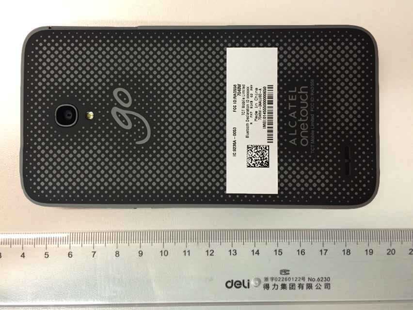
EUT photograph Mobile Phone Mobile Phone Mobile Phone Mobile Phone Mobile Phone Mobile Phone Mobile Phone Battery AE1 Battery AE1 Battery AE2 Battery AE2 Charger AE3 Label of Charger AE3 Charger AE4 Label of Charger AE4 Headset AE5 Headset AE6 Data Cable AE7 Data Cable AE8
Internal Photos
EUT Interior photograph Mobile Phone Mobile Phone Disassembly Mobile Phone Disassembly
RF Exposure Info
No.2013SAR00005 Page 1 of 148 ©Copyright. All rights reserved by TMC Beijing. SAR TEST REPORT No. 2013SAR00005 For TCT Mobile Limited GSM quad bands mobile phone Model name: Beetle Lite Edge 2SIM Marketing name: ONE TOUCH 4005D With Hardware Version: vD15 Software Version: Proto FCC ID: RAD 320 Issued Date: 201 3-03-06 Note: The test results in this test report relate only to the devices specified in this report. This report shall not be reproduced except in full without the written approval of TMC Beijing. Test Laboratory: TMC Beijing, Telecommunication Metrology Center of MIIT No. 52, Huayuan Bei Road, Haidian District, Beijing, P. R. China 100191. Tel:+86(0)10-62304633-2079, Fax:+86(0)10-62304633 Email:[email protected]. www.emcite.com No. 2013SAR00005 Page 2 of 148 Revision Version Report Number Revision Date Memo 2013SAR00005 00 2013-01-29 Initial creation of test report 2013SAR00005 01 2013-02-27 1. Update and add some statements on page 6 2. Update the information in section 4.1 3. Modify the power tolerance for GPRS and EGPRS 2013SAR00005 02 2013-03-06 Update the statement on page 6 No. 2013SAR00005 Page 3 of 148 TABLE OF CONTENT 1 TEST LABORATORY .................................................................................................................... 5 1.1 TESTING LOCATION ........................................................................................................................................ 5 1.2 TESTING ENVIRONMENT ................................................................................................................................. 5 1.3 PROJECT DATA ............................................................................................................................................... 5 1.4 SIGNATURE ..................................................................................................................................................... 5 2 STATEMENT OF COMPLIANCE .................................................................................................. 6 3 CLIENT INFORMATION ................................................................................................................ 7 3.1 APPLICANT INFORMATION .............................................................................................................................. 7 3.2 MANUFACTURER INFORMATION ..................................................................................................................... 7 4 EQUIPMENT UNDER TEST (EUT) AND ANCILLARY EQUIPMENT (AE) ................................. 8 4.1 ABOUT EUT ................................................................................................................................................... 8 4.2 INTERNAL IDENTIFICATION OF EUT USED DURING THE TEST .......................................................................... 8 4.3 INTERNAL IDENTIFICATION OF AE USED DURING THE TEST ............................................................................ 8 5 TEST METHODOLOGY ................................................................................................................ 9 5.1 APPLICABLE LIMIT REGULATIONS .................................................................................................................. 9 5.2 APPLICABLE MEASUREMENT STANDARDS ...................................................................................................... 9 6 SPECIFIC ABSORPTION RATE (SAR) ...................................................................................... 10 6.1 INTRODUCTION ............................................................................................................................................. 10 6.2 SAR DEFINITION .......................................................................................................................................... 10 7 TISSUE SIMULATING LIQUIDS ................................................................................................. 11 7.1 TARGETS FOR TISSUE SIMULATING LIQUID .................................................................................................... 11 7.2 DIELECTRIC PERFORMANCE ......................................................................................................................... 11 8 SYSTEM VERIFICATION ............................................................................................................ 15 8.1 SYSTEM SETUP ............................................................................................................................................. 15 8.2 SYSTEM VERIFICATION ................................................................................................................................. 16 9 MEASUREMENT PROCEDURES .............................................................................................. 17 9.1 TESTS TO BE PERFORMED ............................................................................................................................. 17 9.2 GENERAL MEASUREMENT PROCEDURE ........................................................................................................ 18 9.3 BLUETOOTH & WI-FI MEASUREMENT PROCEDURES FOR SAR .................................................................... 19 9.4 POWER DRIFT ............................................................................................................................................... 20 10 AREA SCAN BASED 1-G SAR ................................................................................................. 20 10.1 REQUIREMENT OF KDB .............................................................................................................................. 20 10.2 FAST SAR ALGORITHMS ............................................................................................................................ 20 11 CONDUCTED OUTPUT POWER .................................................…
Text truncated - open the document above for the full version.
RF Exposure Info
No. 2013SAR00005 Page 99 of 148 1900MHz Date: 2013-1-20 Electronics: DAE4 Sn771 Medium: Body 1900 MHz Medium parameters used: f = 1900 MHz; σ = 1.511 mho/m; ε r = 52.25; ρ = 1000 kg/m 3 Ambient Temperature: 22.3 o C Liquid Temperature: 21.8 o C Communication System: CW Frequency: 1900 MHz Duty Cycle: 1:1 Probe: ES3DV3 - SN3149 ConvF(4.64, 4.64, 4.64) System Validation/Area Scan (81x121x1): Measurement grid: dx=10mm, dy=10mm Reference Value = 83.475 V/m; Power Drift = 0.042 dB Fast SAR: SAR(1 g) = 10.1 mW/g; SAR(10 g) = 5.35 mW/g Maximum value of SAR (interpolated) = 11.5 mW/g System Validation/Zoom Scan (7x7x7)/Cube 0: Measurement grid: dx=5mm, dy=5mm, dz=5mm Reference Value = 83.475 V/m; Power Drift = 0.042 dB Peak SAR (extrapolated) = 16.691 W/kg SAR(1 g) = 10.1 mW/g; SAR(10 g) = 5.36 mW/g Maximum value of SAR (measured) = 11.6 mW/g 0 dB = 11.5 mW/g = 21.21 dB mW/g Fig. B.4 validation 1900MHz 250mW No. 2013SAR00005 Page 100 of 148 2450MHz Date: 2013-01-17 Electronics: DAE4 Sn771 Medium: Head 2450 MHz Medium parameters used: f = 2450 MHz; σ = 1.84 mho/m; ε r = 3 8.69; ρ = 1000 kg/m 3 Ambient Temperature: 22.6 o C Liquid Temperature: 22.0 o C Communication System: CW Frequency: 2450 MHz Duty Cycle: 1:1 Probe: ES3DV3 - SN3149 ConvF(4.49, 4.49, 4.49) System Validation /Area Scan (81x101x1): Measurement grid: dx=10mm, dy=10mm Reference Value = 90.733 V/m; Power Drift = -0.16 dB Fast SAR: SAR(1 g) = 13 mW/g; SAR(10 g) = 5.93 mW/g Maximum value of SAR (interpolated) = 14.9 mW/g System Validation /Zoom Scan (7x7x7)/Cube 0: Measurement grid: dx=5mm, dy=5mm, dz=5mm Reference Value = 90.733 V/m; Power Drift = -0.16 dB Peak SAR (extrapolated) = 27.993 mW/g SAR(1 g) = 13 mW/g; SAR(10 g) = 5.9 mW/g Maximum value of SAR (measured) = 14.8 mW/g 0 dB = 14.9 mW/g = 23.49 dB mW/g Fig. B.5 validation 2450MHz 250mW No. 2013SAR00005 Page 101 of 148 245 0MHz Date: 2013-1-17 Electronics: DAE4 Sn771 Medium: Body 2450 MHz Medium parameters used: f = 2450 MHz; σ = 1.964 mho/m; ε r = 52.03; ρ = 1000 kg/m 3 Ambient Temperature: 22.6 o C Liquid Temperature: 22.0 o C Communication System: CW Frequency: 2450 MHz Duty Cycle: 1:1 Probe: ES3DV3 - SN3149 ConvF(4.15, 4.15, 4.15) System Validation/Area Scan (81x101x1): Measurement grid: dx=10mm, dy=10mm Reference Value = 93.518 V/m; Power Drift = -0.06 dB Fast SAR: SAR(1 g) = 12.9 mW/g; SAR(10 g) = 5.97 mW/g Maximum value of SAR (interpolated) = 14.8 mW/g System Validation/Zoom Scan (7x7x7)/Cube 0: Measurement grid: dx=5mm, dy=5mm, dz=5mm Reference Value = 93.518 V/m; Power Drift = -0.06 dB Peak SAR (extrapolated) = 25.946 mW/g SAR(1 g) = 12.8 mW/g; SAR(10 g) = 5.92 mW/g Maximum value of SAR (measured) = 14.7 mW/g 0 dB = 14.8 mW/g = 23.41 dB mW/g Fig. B.6 validation 2450MHz 250mW No. 2013SAR00005 Page 102 of 148 The SAR system verification must be required that the area scan estimated 1-g SAR is within 3% of the zoom scan 1-g SAR. Table B.1 Comparison between area scan and zoom scan for system verification Band Position Area scan (1g) Zoom scan (1g) Drift (%) 835 Head 2.37 2.41 -1.66 835 Body 2.38 2.37 0.42 1900 Head 9.74 9.71 0.31 1900 Body 10.1 10.1 0.00 2450 Head 13 13 0.00 2450 Body 12.9 12.8 0.78 No. 2013SAR00005 Page 103 of 148 ANNEX C SAR Measurement Setup C.1 Measurement Set-up The Dasy4 or DASY5 system for performing compliance tests is illustrated above graphically. This system consists of the following items: Picture C.1 SAR Lab Test Measurement Set-up A standard high precision 6-axis robot (Stäubli TX=RX family) with controller, teach pendant and software. An arm extension for accommodating the data acquisition electronics (DAE). An isotropic field probe optimized and calibrated for the targeted measurement. A data acquisition electronics (DAE) which performs the signal amplification, signal multiplexing, AD -conversion, offset measurements, mechanical surface detection, collision detection, etc. The unit is battery powered with standard or rechargeable batteries. The signal is optically transmitted to the EOC. The Electro-optical converter (EOC) performs the conversion from optical to electrical signals for the digital communication to the DAE. To use optical surface detection, a special version of the EOC is required. The EOC signal is transmitted to the measurement server. The function of the measurement server is to perform the time critical tasks such as signal filtering, control of the robot operation and fast movement interrupts. The Light Beam used is for probe alignment. This improves the (absolute) accuracy of the probe positioning. A computer running WinXP and the DASY4 or DASY5 software. Remote control and teach pendant as well as additional circuitry for robot safety such as warning lamps, etc. The phantom, the device holder and other accessories according to the targeted measurement. No. 2013SAR00005 Page 104 of 148 C.2 Dasy4 or DASY5 E- field Probe System The SAR measurements were conducted with the dosimetric probe designed in the classical triangular configuration and optimized for dosimetric evaluation. The probe is constructed using the thick film technique; with printed resistive lines on ceramic substrates. The probe is equipped with an optical multifiber line ending at the front of the probe tip. It is connected to the EOC box on the robot arm and provides an automatic detection of the phantom surface. Half of the fibers are connected to a pulsed infrared transmitter, the other half to a synchronized receiver. As the probe approaches the surface, the reflection from the surface produces a coupling from the transmitting to the receiving fibers. This reflection increases first during the approach, reaches maximum and then decreases. If the probe is flatly touching the surface, the coupling is zero. The distance of the coupling maximum to the surface is independent of the surface reflectivity and largely independent of the surface to probe angle. The DASY4 or DASY5 software reads the reflection durning a software approach a…
Text truncated - open the document above for the full version.
RF Exposure Info
©Copyright. All rights reserved by TMC Beijing. The Photos of SAR test No. 2013SAR00005 For TCT Mobile Limited GSM quad bands mobile phone Model name: Beetle Lite Edge 2SIM Marketing name: ONE TOUCH 4005D With Hardware Version: vD15 Software Version: Proto FCC ID: RAD320 Issued Date: 2013-01-29 The test results in this test report relate only to the devices specified in this report. This report shall not be reproduced except in full without the written approval of TMC Beijing. Test Laboratory: TMC Beijing, Telecommunication Metrology Center of MIIT No. 52, Huayuan Bei Road, Haidian District, Beijing, P. R. China 100191. Tel:+86(0)10-62304633-2079, Fax:+86(0)10-62304633 Email:[email protected]. www.emcite.com Picture 1: Constituents of the sample Picture 2: Left Hand Touch Cheek Position Picture 3: Left Hand Tilt 15° Position Picture 4: Right Hand Touch Cheek Position Picture 5: Right Hand Tilt 15° Position Test positions for body: The Body SAR is tested at the following 6 test positions all with the distance =10mm between the EUT and the phantom bottom: Picture 6: Toward Phantom Picture 7: Toward Ground Picture 8: Toward Ground with Headset Picture 9: Left Side Picture 10: Right Side Picture 11: Top Side Picture 12: Bottom Side
Test Report
No.2013TAR009 Page1 of 92 ©Copyright. All rights reserved by TMC Beijing. FCC PART 15C TEST REPORT No. 2013TAR009 for TCT Mobile Limited GSM quad bands mobile phone Model Name: Beetle Lite Edge 2SIM Marketing Name:ONE TOUCH 4005D FCC ID: RAD320 with Hardware Version: Proto Software Version: vD15 Issued Date: 2013-02-25 DAR accreditation (DIN EN ISO/IEC 17025): No. D-PL-12123-01-01 FCC 2.948 Listed: No.733176 IC O.A.T.S listed: No.6629B Note: The test results in this test report relate only to the devices specified in this report. This report shall not be reproduced except in full without the written approval of TMC Beijing. Test Laboratory: TMC Beijing, Telecommunication Metrology Center of Ministry of Industry and Information Technology Shouxiang Science Building, No 51, Xueyuan Road, Haidian District, Beijing, P.R.China 100191 Tel:+86(0)10-62304633-2678, Fax:+86(0)10-62304793 Email:[email protected]. www.emcite.com No.2013TAR009 Page2 of 92 ©Copyright. All rights reserved by TMC Beijing. CONTENTS CONTENTS .................................................................................................................................................. 2 1. TEST LABORATORY ......................................................................................................................... 3 1.1. T ESTING LOCATION ......................................................................................................................... 3 1.2. T ESTING ENVIRONMENT .................................................................................................................. 3 1.3. P ROJECT DATA ................................................................................................................................. 3 1.4. S IGNATURE ...................................................................................................................................... 3 2. CLIENT INFORMATION ................................................................................................................... 4 2.1. A PPLICANT INFORMATION ............................................................................................................... 4 2.2. M ANUFACTURER INFORMATION ...................................................................................................... 4 3. EQUIPMENT UNDER TEST (EUT) AND ANCILLARY EQUIPMENT (AE) ............................. 5 3.1. A BOUT EUT .................................................................................................................................... 5 3.2. I NTERNAL IDENTIFICATION OF EUT USED DURING THE TEST .......................................................... 5 3.3. I NTERNAL IDENTIFICATION OF AE USED DURING THE TEST ............................................................. 5 3.4. N ORMAL ACCESSORY SETTING ........................................................................................................ 6 3.5. G ENERAL DESCRIPTION ................................................................................................................... 6 4. REFERENCE DOCUMENTS ............................................................................................................. 7 4.1. D OCUMENTS SUPPLIED BY APPLICANT ............................................................................................ 7 4.2. R EFERENCE DOCUMENTS FOR TESTING ........................................................................................... 7 5. LABORATORY ENVIRONMENT ..................................................................................................... 8 6. SUMMARY OF TEST RESULTS ....................................................................................................... 9 6.1. S UMMARY OF TEST RESULTS ........................................................................................................... 9 6.2. S TATE MEN TS .................................................................................................................................... 9 7. TEST EQUIPMENTS UTILIZED .................................................................................................... 10 ANNEX A: MEASUREMENT RESULTS ................................................................................................. 11 A.1. MEASUREMENT METHOD ................................................................................................................... 11 A.2. PEAK OUTPUT POWER - CONDUCTED ................................................................................................ 13 A.3. FREQUENCY BAND EDGES - CONDUCTED .......................................................................................... 14 A.4. CONDUCTED EMISSION ...................................................................................................................... 21 A.5. RADIATED EMISSION .......................................................................................................................... 45 A.6. TIME OF OCCUPANCY (DWELL TIME) ................................................................................................ 67 A.7. 20DB BANDWIDTH ............................................................................................................................. 77 A.8. CARRIER FREQUENCY SEPARATION ................................................................................................... 82 A.9. NUMBER OF HOPPING CHANNELS ...................................................................................................... 84 A.10. AC POWERLINE CONDUCTED EMISSION .......................................................................................... 88 No.2013TAR009 Page3 of 92 ©Copyright. All rights reserved by TMC Beijing. 1. Test Laboratory 1.1. Testing Location Company Name: TMC Beijing, Telecommunication Metrology Center of MIIT Address: Shouxiang Science Building, No 51, Xueyuan Road, Haidian District, Beijing, P.R.China Postal Code:…
Text truncated - open the document above for the full version.
Contact Information
Applicant
Zhizhou Gong
Technical Contact
TMC-Telecommunication Metrology Center of M.I.I.TXue Zhen
[email protected]0118662304633
No. 52, Huayuan Bei Road, Haidian District · Beijing · China
Test Firm
TMC-Telecommunication Metrology Center of M.I.I.TChongwen Song
Technical Specifications
| # | Rule Parts | Frequency Range | Power Output |
|---|---|---|---|
| 1 | 15C | 2.40 GHz - 2.48 GHz | 6.80 mW |
Other Applications from TCT Mobile Limited
RAD558
Nov 15, 2015HSUPA/HSDPA/UMTS tribands / GSM quadbands/LTE 6-band mobile phone
Equipment Class
JBP - Part 15 Class B Computing Device Peripheral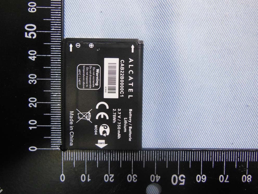
RAD556
Sep 08, 2015CDMA 1X BC0/BC1/BC10 mobile phone
Equipment Class
PCE - PCS Licensed Transmitter held to ear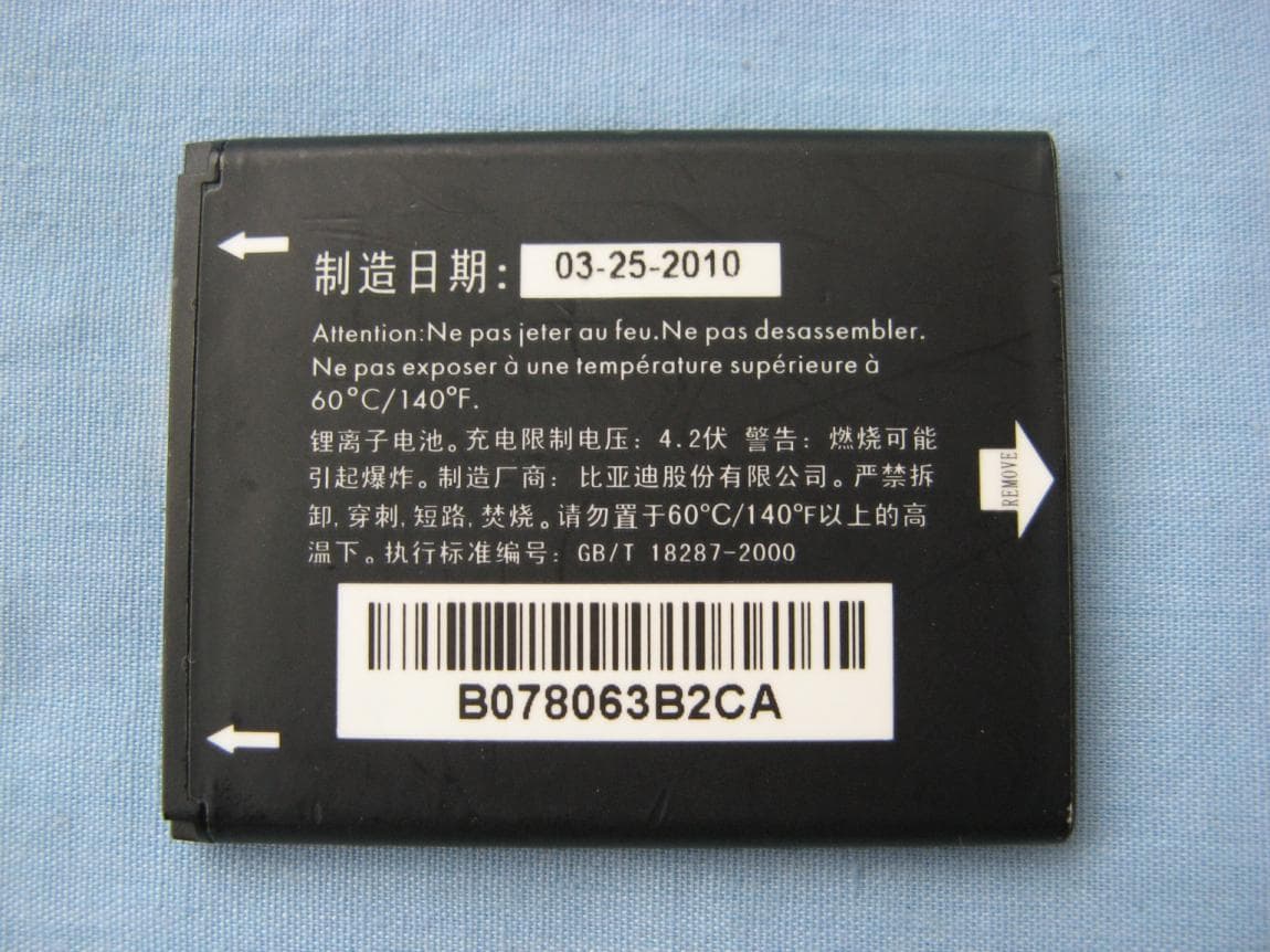
RAD552
Jun 20, 2015GSM Quadband / UMTS Triband mobile phone
Equipment Class
PCE - PCS Licensed Transmitter held to ear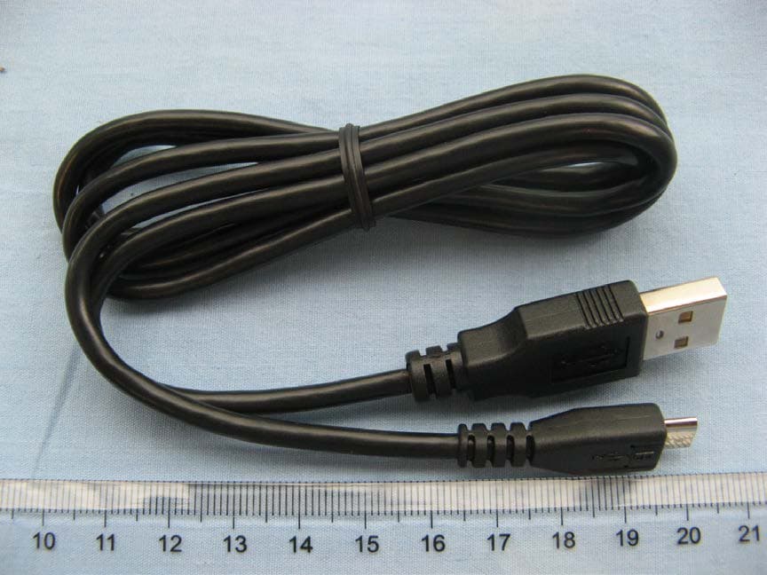
RAD550
Jun 06, 2015HSDPA/HSUPA/HSPA+/UMTS quad band /GSM quad band/LTE 4 band mobile phone
Equipment Class
DSS - Part 15 Spread Spectrum Transmitter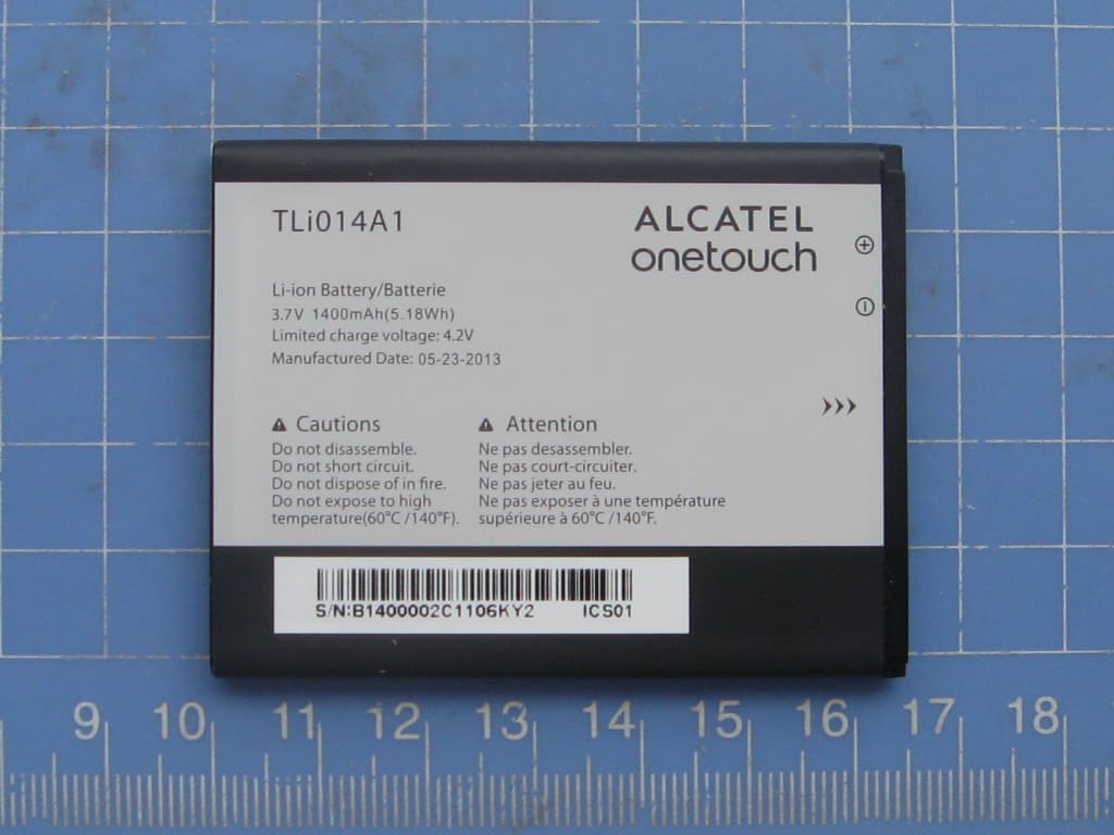
RAD549
May 13, 2015WCDMA tri band / GSM quad band Moblie phone with BT, Wi-Fi functionality.
Equipment Class
DSS - Part 15 Spread Spectrum Transmitter