RAD341LTE USB MODEM
TCT Mobile Limited
Click to zoom
Application Details
- Equipment Class
- PCB - PCS Licensed Transmitter
- Date of Grant
- Jan 14, 2013
- Application Purpose
- Original Equipment
- Date of Application
- Dec 27, 2012
- Equipment Note
- LTE USB MODEM
- Frequency Range
- 1710.00000000 - 1755.00000000
- Company
- TCT Mobile Limited
- Country
- China
Documents & Files
Document Text
Text extracted from the exhibit documents filed with the FCC. Open a document above to read the original.
Users Manual
1 User Manual Table of Contents 1. Safety and Use ....................................................................................................................... 2 2. Installation Guide .................................................................................................................. 3 3. Main Interface Overview ....................................................................................................... 4 4. Connect to Internet ............................................................................................................... 6 5. Statistics ................................................................................................................................. 6 6. Communication ..................................................................................................................... 7 7. Settings ................................................................................................................................ 10 8. Browser ................................................................................................................................ 12 9. Warranty .............................................................................................................................. 12 10. FAQs ................................................................................................................................... 14 11.Certification ........................................................................................................................ 15 2 1. Safety and Use We recommend that you read this chapter carefully before using your modem. The manufacturer disclaims any liability for damage, which may result as a consequence of improper use of the modem or of use contrary to the instructions contained herein. Traffic Safety When driving, do not use the modem: When switched on, the modem emits electromagnetic waves that can interfere with the vehicle’s electronic systems such as the ABS anti‐lock braking system or airbags. To prevent any of these issues from occurring, please do not place the modem on top of the dashboard or within an airbag deployment area. Please check with your car dealer or the car manufacturer to make sure that the dashboard is adequately shielded from modem RF energy. Conditions of Use 1. Switch the modem off before boarding an aircraft. 2. Switch the modem off when you are in health care facilities, except in designated areas. As with many other types of equipment now in regular use, mobile Tele‐modems can interfere with other electrical or electronic devices, or equipment‐using radio f requencies. 3. Switch the modem off when you are near gas or flammable liquids. Strictly obey all signs and instructions posted in a fuel depot, petrol station, chemical plant, or in any potentially explosive atmosphere. 4. When the modem is switched on, it should be kept at least 15 cm from any medical device such as a pacemaker, a hearing aid or insulin pump, etc. 5. Do not let children use the modem without supervision. The modem may contain small parts that could become detached and create a choking hazard. 6. When replacing the cover, please note that the modem may co ntain substances that could create an allergic reaction. 7. Always handle the modem with care and keep it in a clean and dust‐free place. 8. Do not allow the USB‐Modem to be exposed to adverse weather or environmental conditions (moisture, humidity, rain, infiltration of liquids, dust, sea air, etc). The manufacturer’s recommended operating temperature range is ‐10°C to +45°C. 9. Do not open, dismantle or attempt to repair the modem yourself. 3 10. Do not drop, throw or bend the modem. 11. Do not paint the modem. 12. Recommend to use the USB Y cable to ensure the power supply. Collection Point: This symbol on the modem means that it must be taken to collection points at the end of their life: Municipal waste disposal centers with specific bins for these items of equipment Collection bins at points of sale. They will then be recycled, preventing substances being disposed of in the environment, so that their components can be reused. In European Union countries: These collection points are accessible free of charge. All products with this symbol must be brought to these collection points. In non European Union jurisdictions: Items of equipment with this symbol are not to be thrown into ordinary bins if your jurisdiction or your region has suitable recycling and collection facilities; instead they are to be taken to collection points for them to be recycled. In the United States, please visit www.recyclewirelessphones.org for more information on recycling wireless products. Protection against theft The modem is identified by an IMEI (modem serial number) shown on the packaging label and in the modem’s dashboard. We recommend that you note the number the first time you use the modem by opening the dashboard “Settings” > “Diagnostics” to get it. Disclaimer There may be certain differences between the user manual description and the modem’s operation, depending on the software release of the modem or specific operator services. 2. Installation Guide 2.1 Installation Guide for Windows Installation procedures may vary based on the operating system installed on your PC. 4 The following instructions are based on the Windows XP OS: Turn on your PC and plug the modem into the USB interface slot to begin software installation. Windows should automatically detect the new device and will prompt you to begin installation. After following the prompts of installation setup, upon completion, a shortcut will be placed on your desktop for quick future access. Note: 1. If installation “auto‐run” does not begin, you will need to locate the “autoRun.exe)” file in the driver path, and Double‐Click on AutoRun.exe to run the installation manually. 2. A Micro‐SD card is an optional accessory. 3. Please do not remove the USIM/SIM…
Text truncated - open the document above for the full version.
Cover Letter(s)
Date: Dec. 27, 2012 To: Federal Communications Commission, Authorization & Evaluation Division, 7435 Oakland Mills Road, Columbia, MD 21046 To Whom It May Concern: TCT Mobile Limited the undersigned, hereby authorizes Mr. Wu Xuewen from Shenzhen Morlab Communications Technology Co., Ltd., to act on the behalf of TCT Mobile Limited solely in matters relating to the application for an FCC equipment authorization for FCC ID: RAD341 including the signing of documents in connection with this Application. Necessary acts carried out by Shenzhen Morlab Communications Technology Co., Ltd on our behalf of TCT Mobile Limited in connection with the Application shall have the same effect as acts of TCT Mobile Limited. TCT Mobile Limited also hereby certify that no party to this application is subject to a denial of benefits, including FCC benefits, pursuant to Section 5301 of the Anti-Drug Abuse Act of 1988, 21 U.S.C. 853(a). Thank you for your attention to this matter. Signatory Gong ZhiZhou Validation Project Manager TCT Mobile Limited
Cover Letter(s)
Date: Dec. 27, 2012 To: Federal Communications Commission, Authorization & Evaluation Division, 7435 Oakland Mills Road, Columbia, MD 21046 Re: TCT Mobile Limited FCC ID: RAD341 FCC Part 22 & 24 & 27 Certification Confidentiality Request Gentlemen: This letter is to comply with 47 CFR 0.457 and 0.459 pertaining to confidentiality material.TCT Mobile Limited requests that the following documents regarding this submission for FCC ID: RAD341 be kept confidential: Exhibit Type File Name Block Diagram CONF APPENDIX RAD341_Block Diagram.pdf Schematics CONF APPENDIX RAD341 _Schematics.pdf Operational Description CONF APPENDIX RAD341 _Operational Description.pdf Part list CONF APPENDIX RAD341 _BOM.pdf Tune-Up-Procedure CONF APPENDIX RAD341 _Tune up procedure.pdf Those documents contain detailed system and equipment description and related information about the product which TCT Mobile Limited considers to be confidential proprietary, a custom design and, otherwise, not releasable to the general public. Since this design is a basis form which future technological products will evolve, TCT Mobile Limited considers this information would be of benefit to its competitors, and that the disclosure of the information in these documents would give competitors an unfair advantage in the market. Signatory Gong ZhiZhou TCT Mobile Limited
External Photos
External Photos 1. EUT front view 2. EUT rear view 3. EUT left side view 4. EUT right side view 5. EUT top view 6. EUT bottom view
ID Label/Location Info
FCC ID: RAD341 Label Size: 20*10mm Label Location FCC ID LABEL Location
ID Label/Location Info
FCC ID: RAD341 Label Size: 20*10mm Label Location FCC ID LABEL Location
ID Label/Location Info
TCT Mobile Limited Date: Dec. 27, 2012 Equipment Authorization Division Office of Engineering and Technology Federal Communications Commission 7435 Oakland Mills Road Columbia, MD 21046 Ref: FCC ID: RAD341 Dear Sirs: TCT Mobile Limited. requests acceptance of the labeling proposal described below for HSPA USB Modem bearing FCC identifier RAD341. The subject HSPA USB Modem are compact handheld models as shown in figure 1, authorized under 47CFR Part 22H&24E&27L for GSM&WCDMA<E mobile services. Figure 1. Because the majority of the HSPA USB Modem housing is composed of indicators, rotating USB head, there is extremely limited space available to attach the required label carrying the FCC identifier. TCT Mobile Limited. proposes placing the label carrying the FCC identifier inside product body as shown in figure 2. Figure 2. FCC ID Label TCT Mobile Limited The consumer packaging for these models is a "gift box" which does not allow the HSPA+ USB Modem to be seen at time of purchase. In order to meet the requirements of 47CFR Part 2.925 (d), TCT Mobile Limited. will add the FCC identifier "RAD341" to the outside of the consumer "gift box" packaging. Thank you for your attention to this matter. Yours Sincerely, Zhizhou Gong Project Engineer
Internal Photos
Internal Photos 1. EUT without cap view 2. EUT Inside view 3. Mainboard front view with shielding 4. Mainboard rear view with shielding 5. Mainboard front view without shielding 6. Mainboard rear view without shielding 7. GSM/WCDMA/LTE antenna view Main antenna Ancillary antenna
RF Exposure Info
FCC SAR Test Report Report Format Version 5.0.0 Page No. : 1 of 31 Report No. : SA121213C18 Issued Date : Dec. 28, 2012 Revision : R01 FCC SAR Test Report Report No. : SA121213C18 Applicant : TCT Mobile Limited Address : 5F, C building, No. 232, Liang Jing Road ZhangJiang High-Tech Park, Pudong Area Shanghai, P.R. China. 201203 Product : LTE USB Modem FCC ID : RAD341 Brand : Alcatel Model No. : One Touch L100G Standards : FCC 47 CFR Part 2 (2.1093) / IEEE C95.1:1991 / IEEE 1528:2003 FCC OET Bulletin 65 Supplement C (Edition 01-01) KDB 447498 D01 v04 / KDB 447498 D02 v02 / KDB 941225 D05 v01 Date of Testing : Dec. 26, 2012 ~ Dec. 27, 2012 CERTIFICATION: The above equipment have been tested by Bureau Veritas Consumer Products Services (H.K.) Ltd., China Branch - Dongguan Lab, and found compliance with the requirement of the above standards. The test record, data evaluation & Equipment Under Test (EUT) configurations represented herein are true and accurate accounts of the measurements of the sample’s SAR characteristics under the conditions specified in this report. It should not be reproduced except in full, without the written approval of our laboratory. The client should not use it to claim product certification, approval, or endorsement by A2LA or any government agencies. No: 2951.01 Prepared By : Ivonne Wu / Senior Specialist Approved By : Roy Wu / Manager This report is for your exclusive use. Any copying or replication of this report to or for any other person or entity, or use of our name or trademark, is permitted only with our prior written permission. This report sets forth our findings solely with respect to the test samples identified herein. The results set forth in this report are not indicative or representative of the quality or characteristics of the lot from which a test sample was taken or any similar or identical product unless specifically and expressly noted. Our report includes all of the tests requested by you and the results thereof based upon the information that you provided to us. You have 60 days from date of issuance of this report to notify us of any material error or omission caused by our negligence, provided, however, that such notice shall be in writing and shall specifically address the issue you wish to raise. A failure to raise such issue within the prescribed time shall constitute your unqualified acceptance of the completeness of this report, the tests conducted and the correctness of the report contents. Unless specific mention, the uncertainty of measurement has been explicitly taken into account to declare the compliance or non-compliance to the specification. FCC SAR Test Report Report Format Version 5.0.0 Page No. : 2 of 31 Report No. : SA121213C18 Issued Date : Dec. 28, 2012 Revision : R01 Table of Contents Release Control Record ............................................................................................................................................................... 3 1. Summary of Maximum SAR Value ....................................................................................................................................... 4 2. Description of Equipment Under Test ................................................................................................................................. 5 3. SAR Measurement System ................................................................................................................................................... 6 3.1 Definition of Specific Absorption Rate (SAR) ................................................................................................................ 6 3.2 SPEAG DASY System ................................................................................................................................................. 6 3.2.1 Robot.................................................................................................................................................................. 7 3.2.2 Probes ................................................................................................................................................................ 8 3.2.3 Data Acquisition Electronics (DAE) .................................................................................................................... 8 3.2.4 Phantoms ........................................................................................................................................................... 9 3.2.5 Device Holder ..................................................................................................................................................... 9 3.2.6 System Validation Dipoles .................................................................................................................................. 9 3.2.7 Tissue Simulating Liquids ................................................................................................................................. 10 3.3 SAR System Verification ............................................................................................................................................ 13 3.4 SAR Measurement Procedure ................................................................................................................................... 14 3.4.1 Area & Zoom Scan Procedure ......................................................................................................................... 14 3.4.2 Volume Scan Procedure................................................................................................................................... 14 3.4.3 Power Drift Monitoring ...................................................................................................................................... 14 3.4.4 Spatial Peak SAR Evaluation .....................................................................................................................…
Text truncated - open the document above for the full version.
RF Exposure Info
SZ12110030S01 Page 2 of 79 DIRECTORY DIRECTORY....................................................................................................................................2 1. TESTING LABORATORY.........................................................................................................4 1.1. Identification of the Responsible Testing Laboratory................................................................. 4 1.2. Identification of the Responsible Testing Location.....................................................................4 1.3. Accreditation Certificate..............................................................................................................4 1.4. List of Test Equipments...............................................................................................................4 2. TECHNICAL INFORMATION..................................................................................................5 2.1. Identification of Applicant...........................................................................................................5 2.2. Identification of Manufacturer.....................................................................................................5 2.3. Equipment Under Test (EUT)......................................................................................................5 2.3.1. Photographs of the EUT............................................................................................................5 2.3.2. Identification of all used EUTs.................................................................................................5 2.4. Applied Reference Documents.................................................................................................... 6 2.5. Device Category and SAR Limits................................................................................................6 2.6. Test Environment/Conditions......................................................................................................7 3. SPECIFIC ABSORPTION RATE (SAR)...................................................................................8 3.1. Introduction..................................................................................................................................8 3.2. SAR Definition............................................................................................................................ 8 4. SAR MEASUREMENT SETUP..................................................................................................9 4.1. The Measurement System............................................................................................................9 4.2. Probe............................................................................................................................................ 9 4.3. Phantom..................................................................................................................................... 11 4.4. Device Holder............................................................................................................................11 5. TISSUE SIMULATING LIQUIDS........................................................................................... 12 6. UNCERTAINTY ASSESSMENT............................................................................................. 14 6.1. UNCERTAINTY EVALUATION FOR EUT SAR TEST....................................................... 14 6.2. UNCERTAINTY FOR SYSTEM PERFORMANCE CHECK................................................ 15 7. SAR MEASUREMENT EVALUATION................................................................................. 17 7.1. System Setup..............................................................................................................................17 7.2. Validation Results......................................................................................................................17 8. OPERATIONAL CONDITIONS DURING TEST..................................................................18 SZ12110030S01 Page 3 of 79 8.1. Body-worn Configurations........................................................................................................ 18 8.2. Measurement procedure.............................................................................................................18 8.3. Description of interpolation/extrapolation scheme....................................................................19 9. 3G MEASUREMENT PROCEDURES....................................................................................20 9.1. Procedures Used To Establish Test Signal................................................................................ 20 9.2. SAR Measurement Conditions for WCDMA............................................................................20 9.3. Output Power Verification.........................................................................................................20 9.4. Test Procedure........................................................................................................................... 20 10. MEASUREMENT OF CONDUCTED PEAK OUTPUT POWER..................................... 21 11. TEST RESULTS LIST.............................................................................................................24 ANNEX A PHOTOGRAPHS OF THE EUT...............................................................................26 ANNEX B GRAPH TEST RESULTS...........................................................................................30 Change History IssueDateReason for change 1.0Dec. 27, 2012First edition SZ12110030S01 Page 4 of 79 1. Testing Laboratory 1.1. Identification of the Responsible Testing Laboratory Company Name:Shenzhen Morlab Communications Technology Co., Ltd. Department:Morlab Laboratory Address:3/F, Electronic Testing Building, Shahe Road, Nanshan Di…
Text truncated - open the document above for the full version.
Test Report
Report No.: SZ12110030W02 Page 2 of 61 TABLE OF CONTENTS 1. GENERAL INFORMATION .................................................................................................... 3 1.1 EUT Description ......................................................................................................................... 3 1.2 Test Standards and Results ........................................................................................................ 4 1.3 Facilities and Accreditations ...................................................................................................... 5 2. 47 CFR PART 2, PART 27 REQUIREMENTS ....................................................................... 6 2.1 Transmitter Conducted Output Power ..................................................................................... 6 2.2 Occupied Bandwidth ................................................................................................................ 13 2.3 Frequency Stability ................................................................................................................... 18 2.4 Peak to Average Radio .............................................................................................................. 20 2.5 Conducted Spurious Emissions ............................................................................................... 24 2.6 Band Edge ................................................................................................................................. 32 2.7 Transmitter Radiated Power (EIRP/ERP) ............................................................................. 41 2.8 Radiated Spurious Emissions .................................................................................................. 45 Change History Issue Date Reason for change 1.0 Dec 27, 2012 First edition Report No.: SZ12110030W02 Page 3 of 61 1. GENERAL INFORMATION 1.1 EUT Description EUT Type ............................ One Touch L100G Serial No. ............................. (n.a, marked #1 by test site) Hardware Version ................ V3.0 Software Version ................. Applicant ............................. Manufacturer ....................... S1_B15001S_1110000_B10001S TCT Mobile Limited 5F, C building, No. 232, Liang Jing Road Zhang Jiang High-Tech Park, Pudong Area Shanghai, P.R. China. 201203 TCL COMMUNICATION TECHNOLOGY HOLDINGS LIMITED 70 Huifeng 4rd, Zhong Kai Hi-tech Development District, Huizhou, Guangdong 516006 P.R. China (TCL Mobile Communication Co., Ltd. Huizhou) Modulation Type.................. LTE Band 17: QPSK, 16QAM LTE Band 4: QPSK, 16QAM Tx Frequency Range............ LTE Band 17: 704MHz~716MHz LTE Band 4: 1710MHz~1755MHz Rx Frequency Range ........... LTE Band 17: 734MHz~746MHz LTE Band 4: 2110MHz~2155MHz Emission Designator ............ 4M52G7D (LTE Band 17, QPSK, BW 5MHz) 4M52W7D (LTE Band 17, 16QAM, BW 5MHz) 9M07G7D (LTE Band 17, QPSK, BW 10MHz) 9M08W7D (LTE Band 17, 16QAM, BW 10MHz) 1M11G7D (LTE Band 4, QPSK, BW 1.4MHz) 1M10W7D (LTE Band 4, 16QAM, BW 1.4MHz) 2M76G7D (LTE Band 4, QPSK, BW 3MHz) 2M76 W7D (LTE Band 4, 16QAM, BW 3MHz) 4M51G7D (LTE Band 4, QPSK, BW 5MHz) 4M53 W7D (LTE Band 4, 16QAM, BW 5MHz) 9M06G7D (LTE Band 4, QPSK, BW 10MHz) 9M08 W7D (LTE Band 4, 16QAM, BW 10MHz) 13M5G7D (LTE Band 4, QPSK, BW 15MHz) 13M5 W7D (LTE Band 4, 16QAM, BW 15MHz) 18M5G7D (LTE Band 4, QPSK, BW 20MHz) 18M4W7D (LTE Band 4, QPSK, BW 20MHz) Antenna Type ....................... PIFA Antenna Antenna Gain ....................... LTE Band 17: -2.1dBi LTE Band 4: -2.2dBi Power Supply ...................... 5V DC Power Report No.: SZ12110030W02 Page 4 of 61 1.2 Test Standards and Results The objective of the report is to perform testing according to 47 CFR Part 2 and Part 27 for the EUT FCC ID Certification: No. Identity Document Title 1 47 CFR Part 2 Frequency Allocations and Radio Treaty Matters; General Rules and Regulations 2 47 CFR Part 27 Miscellaneous Wireless Communications Services Test detailed items/section required by FCC rules and results are as below: No. Section Description Result 1 2.1046(a) Transmitter Conducted Output Power PASS 2 2.1049 27.53(g) Occupied Bandwidth PASS 3 2.1055 27.54 Frequency Stability PA S S 4 27.50(d) (5) Peak to Average Radio PASS 5 2.1051 27.53(g)(h) Conducted Spurious Emissions PASS 6 27.53(g)(h) Band Edge PASS 7 2.1046 27.50 (d)(4) 27.50(c) (10)(11) Equivalent Isotropic Radiated Power PASS 8 2.1053 27.53(g)(h) Radiated Spurious Emissions PASS Report No.: SZ12110030W02 Page 5 of 61 1.3 Facilities and Accreditations 1.3.1 Facilities Shenzhen Morlab Communications Technology Co., Ltd. Morlab Laboratory is a testing organization accredited by China National Accreditation Service for Conformity Assessment (CNAS) according to ISO/IEC 17025. The accreditation certificate number is L3572. All measurement facilities used to collect the measurement data are located at 3/F, Electronic Testing Building, Shahe Road, Xili, Nanshan District, Shenzhen, 518055 P. R. China. The test site is constructed in conformance with the requirements of TIA/EIA 603.D: 2010, ANSI C63.4: 2009 and CISPR Publication 22: 2010. The FCC registration number is 741109. 1.3.2 Test Environment Conditions During the measurement, the environmental conditions were within the listed ranges: Temperature (°C): 15 - 35 Relative Humidity (%): 30 - 60 Atmospheric Pressure (kPa): 86 - 106 Report No.: SZ12110030W02 Page 6 of 61 2. 47 CFR PART 2, PART 27 REQUIREMENTS 2.1 Transmitter Conducted Output Power 2.1.1 Requirement According to FCC section 2.1046(a), for transmitters other than single sideband, independent sideband and controlled carrier radiotelephone, power output shall be measured at the RF output terminals when the transmitter is adjusted in accordance with the tune-up procedure to give the values of current and voltage on the circuit elements specified in FCC section 2.1033(c)(8). 2.1.2 Test Description 1. Test Setup: The EUT, w…
Text truncated - open the document above for the full version.
Test Report
Report No.: SZ12110030W01 Page 2 of 139 TABLE OF CONTENTS 1. GENERAL INFORMATION .................................................................................................... 3 1.1 EUT Description ......................................................................................................................... 3 1.2 Test Standards and Results ........................................................................................................ 5 1.3 Facilities and Accreditations ...................................................................................................... 6 2. 47 CFR PART 2, PART 22H & 24E REQUIREMENTS ........................................................ 7 2.1 Conducted RF Output Power .................................................................................................... 7 2.2 99% Occupied Bandwidth ....................................................................................................... 19 2.3 Frequency Stability ................................................................................................................... 34 2.4 Conducted Out of Band Emissions ......................................................................................... 41 2.5 Band Edge ................................................................................................................................. 79 2.6 Transmitter Radiated Power (EIRP/ERP) ............................................................................. 95 2.7 Radiated Out of Band Emissions .......................................................................................... 102 Change History Issue Date Reason for change 1.0 Dec 27, 2012 First edition Report No.: SZ12110030W01 Page 3 of 139 1. GENERAL INFORMATION 1.1 EUT Description EUT Ty…
Text truncated - open the document above for the full version.
Contact Information
Applicant
Zhizhou Gong
Test Firm
Shenzhen Morlab Communications Technology Co., LtdIvy zhu
Technical Specifications
| # | Rule Parts | Frequency Range | Power Output | Emission | Tolerance |
|---|---|---|---|---|---|
| 29 | 27 | 1.71 GHz - 1.75 GHz | 103.00 mW | 18M4W7D | 0.01 ppm |
Other Applications from TCT Mobile Limited
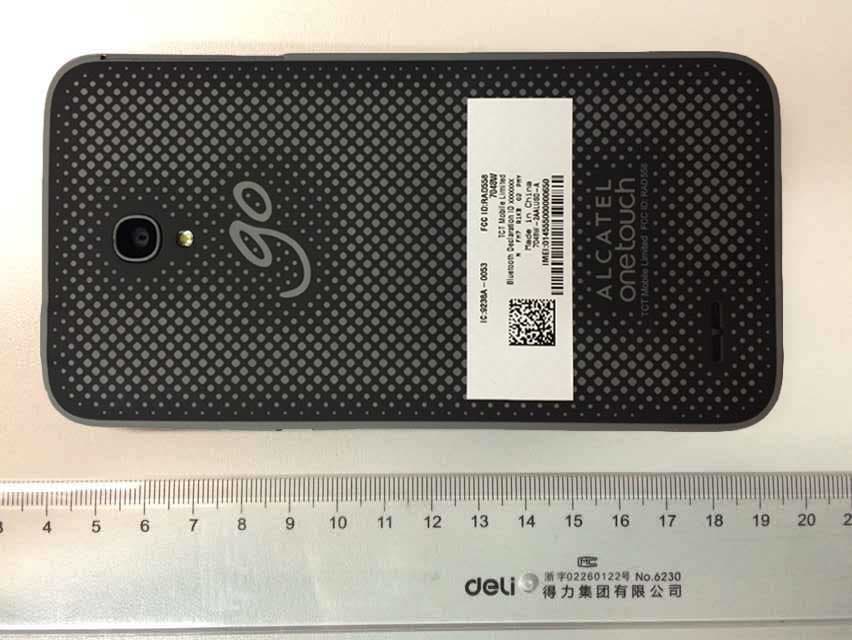
RAD558
Nov 15, 2015HSUPA/HSDPA/UMTS tribands / GSM quadbands/LTE 6-band mobile phone
Equipment Class
JBP - Part 15 Class B Computing Device Peripheral
RAD556
Sep 08, 2015CDMA 1X BC0/BC1/BC10 mobile phone
Equipment Class
PCE - PCS Licensed Transmitter held to ear
RAD552
Jun 20, 2015GSM Quadband / UMTS Triband mobile phone
Equipment Class
PCE - PCS Licensed Transmitter held to ear
RAD550
Jun 06, 2015HSDPA/HSUPA/HSPA+/UMTS quad band /GSM quad band/LTE 4 band mobile phone
Equipment Class
DSS - Part 15 Spread Spectrum Transmitter
RAD549
May 13, 2015WCDMA tri band / GSM quad band Moblie phone with BT, Wi-Fi functionality.
Equipment Class
DSS - Part 15 Spread Spectrum Transmitter