RAD404LTE USB Modem/LTE AP
TCT Mobile Limited
Click to zoom
Application Details
- Equipment Class
- JBP - Part 15 Class B Computing Device Peripheral
- Date of Grant
- Jul 29, 2013
- Application Purpose
- Original Equipment
- Date of Application
- Jul 29, 2013
- Equipment Note
- LTE USB Modem/LTE AP
- Company
- TCT Mobile Limited
- Country
- China
Documents & Files
Document Text
Text extracted from the exhibit documents filed with the FCC. Open a document above to read the original.
Users Manual
Quick Start Guide Welcome! This manual brief is the profile of your USB‐Modem, about the details of how to set the management parameters, see help information on the web management page. www.sar‐tick.com This product meets applicable national SAR limits of 2.0W/kg. The specific maximum SAR values can be found in the following section of this user guide. When carrying the product or using it while worn on your body, either use an approved accessory such as a holster or otherwise maintain a distance of 5 mm from the body to ensure compliance with RF exposure requirements. Note that the product may be transmitting even if you are not making a phone call. Getting to Know Your Modem How to start your modem 1. Remove the back cover. 2. Insert the SIM/UMSIM card into card slot on back of modem. 3. Insert the USB modem into computer’s USB port. 4. When the installation is complete, the modem’s web management page is displayed, the modem connects to the network automatically. The modem’s web management page will be displayed every time automatically when the modem is inserted into the computer. Note: Do not remove the SIM/USIM card when the card is in use. Number Description 1 USB interface 2 SMS LED 3 Network LED 4 SIM/USIM Card Slot 5 Micro‐SD Card Slot If the modem does not be installed automatically, find the AutoRun.exe (in windows OS) file in modem’s root and double‐click it to run. If the connection failed, access http://192.168.1.1 to check the status. If you cannot access http://192.168.1.1, disconnect other network, remove the modem and re‐insert it, or restart your computer. Recommend to use the USB Y cable to ensure the power supply LED Indicates (Following table are listed the LED Indicates for each status.) LED TYPE LED Indicator Description (state) Network LED Lilac Light constant for seconds Power supply finished Orange Light Fast Flashing(5Hz) Network Searching Constant Orange Light Out of order Red Light Slow Flashing (1Hz) Registering into LTE Network Constant Red Light Registered to LTE Network Green Light Slow Flashing (1Hz) Registering into 3G network Constant Green Light Registered to 3G network Blue Light Slow Flashing (1Hz) Registering into 2G network Constant Blue Light Registered to 2G network SMS LED Blue Light Slow Flashing (Continuation 5 s) Receive SMS Blue Light close No new received SMS Safety and Use We recommend that you read this chapter carefully before using the USB‐Modem. The manufacturer disclaims any liability for damage, which may result as a consequence of improper use of the USB‐Modem or of use contrary to the instructions contained herein. Traffic Safety When driving, do not use the USB‐Modem When switched on, the USB‐Modem emits electromagnetic waves that can interfere with the vehicle’s electronic systems such as ABS anti‐lock brakes or airbags. To ensure that there is no problem, do not place the USB‐Modem on top of the dashboard or within an airbag deployment area. Check with your car dealer or the car manufacturer to make sure that the dashboard is adequately shielded from modem RF energy. Conditions of Use Switch the USB‐Modem off before boarding an aircraft. Switch the USB‐Modem off when you are in health care facilities, except in designated areas. As with many other types of equipment now in regular use, the USB‐Modem can interfere with other electrical or electronic devices, or equipment‐using radio frequencies. Switch the USB‐Modem off when you are near gas or flammable liquids. Strictly obey all signs and instructions posted in a fuel depot, petrol station, chemical plant, or in any potentially explosive atmosphere. When the USB‐Modem is switched on, it should be kept at least 15 cm from any medical device such as a pacemaker, a hearing aid or insulin pump, etc. Do not let children use the USB‐Modem without supervision. When replacing the cover, please note that the USB‐Modem may contain substances that could create an allergic reaction. Always handle the USB‐Modem with care and keep it in a clean and dust‐free place. Do not allow the USB‐Modem to be exposed to adverse weather or environmental conditions (moisture, humidity, rain, infiltration of liquids, dust, sea air, etc). The manufacturer’s recommended operating temperature range is ‐10°C to +50°C. Do not open, dismantle or attempt to repair the USB‐Modem yourself. Do not drop, throw or bend the USB‐Modem. Do not paint it. WEEE Approval The USB‐Modem is in compliance with the essential requirements and other relevant provisions of the Waste Electrical and Electronic Equipment Directive 2002/96/EC (WEEE Directive). RoHs Approval The USB‐Modem is in compliance with the restriction of the use of certain hazardous substances in electrical and electronic equipment Directive 2002/95/EC (RoHs Directive). Radio Waves Proof of compliance with international standards (ICNIRP) or with European Directive 1999/5/EC (R&TTE) is required of all modem models before they can be put on the market. The protection of the health and safety for the user and any other person is an essential requirement of these standards or this directive. THIS DEVICE MEETS INTERNATIONAL GUIDELINES FOR EXPOSURE TO RADIO WAVES. The USB‐Modem is a radio transmitter and receiver. It is designed not to exceed the limits for exposure to radio waves (radio frequency electromagnetic fields) recommended by international guidelines. The guidelines were developed by an independent scientific organization (ICNIRP) and include a substantial safety margin designed to assure the safety of all persons, regardless of age and health. The radio wave exposure guidelines use a unit of measurement known as the Specific Absorption Rate, or SAR. The SAR limit for mobile devices is 2 W/kg. Tests for SAR are conducted using standard operating positions with the device transmitting at its highest certified power level in all tested frequency bands. The highest SAR values under the ICNIRP guidelines for this device mo…
Text truncated - open the document above for the full version.
Cover Letter(s)
Date: 27 Sep, 2011 To: Federal Communications Commission, Authorization & Evaluation Division, 7435 Oakland Mills Road, Columbia, MD 21046 To Whom It May Concern: TCT Mobile Limited the undersigned, hereby authorizes Ms Ivy Zhu from Shenzhen Morlab Communications Technology Co., Ltd., to act on the behalf of TCT Mobile Limited solely in matters relating to the application for an FCC equipment authorization for FCC ID: RAD404including the signing of documents in connection with this Application. Necessary acts carried out by Shenzhen Morlab Communications Technology Co., Ltd on our behalf of TCT Mobile Limited in connection with the Application shall have the same effect as acts of TCT Mobile Limited. TCT Mobile Limited also hereby certify that no party to this application is subject to a denial of benefits, including FCC benefits, pursuant to Section 5301 of the Anti-Drug Abuse Act of 1988, 21 U.S.C. 853(a). Thank you for your attention to this matter. Signatory Gong ZhiZhou Validation Project Manager TCT Mobile Limited
Cover Letter(s)
Date: 27 Sep, 2011 To: Federal Communications Commission, Authorization & Evaluation Division, 7435 Oakland Mills Road, Columbia, MD 21046 Re: TCT Mobile Limited FCC ID: RAD404 FCC Part 15B Certification FCC Part 22 Certification FCC Part 24 Certification Confidentiality Request Gentlemen: This letter is to comply with 47 CFR 0.457 and 0.459 pertaining to confidentiality material.TCT Mobile Limited requests that the following documents regarding this submission for FCC ID: RAD404 be kept confidential: Exhibit Type File Name Block Diagram CONF APPENDIX RAD404_Block Diagram.pdf Schematics CONF APPENDIX RAD404 _Schematics.pdf Operational Description CONF APPENDIX RAD404 _Operational Description.pdf Part list CONF APPENDIX RAD404 _BOM.pdf Tune-Up-Procedure CONF APPENDIX RAD404 _Tune up procedure.pdf Those documents contain detailed system and equipment description and related information about the product which TCT Mobile Limited considers to be confidential proprietary, a custom design and, otherwise, not releasable to the general public. Since this design is a basis form which future technological products will evolve, TCT Mobile Limited considers this information would be of benefit to its competitors, and that the disclosure of the information in these documents would give competitors an unfair advantage in the market. Signatory Gong ZhiZhou TCT Mobile Limited
External Photos
External Photos 1. EUT full view with accessories 2. EUT front view 3. EUT rear view 4. EUT left side view 5. EUT right side view 6. EUT top view 7. EUT bottom view
ID Label/Location Info
FCC ID: RAD404 Label Size: 25*4mm Label Location FCC ID LABEL LOCATION
Internal Photos
In ternal Photos 1. EUT uncover view 2. Mainboard front view with shielding 3. Mainboard rear view with shielding 4. Mainboard front view without shielding 5. Mainboard rear view without shielding 6. GSM/WCDMA view 7. GSM/WCDMA antenna view
Test Report
Report No.: SZ13060036E02 Page 2 of 18 TABLE OF CONTENTS 1. GENERAL INFORMATION .................................................................................................... 3 1.1 EUT Description ......................................................................................................................... 3 1.2 Test Standards and Results ........................................................................................................ 5 1.3 Facilities and Accreditations ...................................................................................................... 6 1.3.1 Facilities .................................................................................................................................... 6 1.3.2 Test Environment Conditions .................................................................................................... 6 1.3.3 Measurement Uncertainty ......................................................................................................... 6 2. TEST CONDITIONS SETTING............................................................................................... 7 2.1 Test Mode .................................................................................................................................... 7 2.2 Test Setup and Equipments List ................................................................................................ 8 2.2.1 Conducted Emission.................................................................................................................. 8 2.2.2 Radiated Emission ..................................................................................................................... 9 3. 47 CFR PART 15B REQUIREMENTS .................................................................................. 12 3.1 Conducted Emission ................................................................................................................. 12 3.1.1 Requirement ............................................................................................................................ 12 3.1.2 Test Description ...................................................................................................................... 12 3.1.3 Test Result ............................................................................................................................... 12 3.2 Radiated Emission .................................................................................................................... 15 3.2.1 Requirement ............................................................................................................................ 15 3.2.2 Test Description ...................................................................................................................... 15 3.2.3 Frequency range of measurement ........................................................................................... 15 3.2.4 Test Result ............................................................................................................................... 16 Change History Issue Date Reason for change 1.0 July 15, 2013 First edition Report No.: SZ13060036E02 Page 3 of 18 1. GENERAL INFORMATION 1.1 EUT Description EUT Type ..........................LTE USB Modem/LTE AP Serial No. ..........................(n.a., marked #1 by test site) Hardware Version ............ .V2.0 Software Version ............... Applicant ........................... Manufacturer ..................... S1_B15001S_1110000_B10001S TCT Mobile Limited 5F, C building, No. 232, Liang Jing Road ZhangJiang High-Tech Park, Pudong Area Shanghai, P.R. China. 20120 TCL COMMUNICATION TECHNOLOGY HOLDINGS LIMITED 70 Huifeng 4rd, ZhongKai Hi-tech Development District, Huizhou, Guangdong 516006 P.R. China Modulation Type .............. .GMSK,8PSK,QPSK, DSSS Ancillary Equipment 1 ......AC Adapter Brand Name: ALCATEL Model No.: one touch UC12US Serial No.: (n.a. marked #1 by test site) Rated Input: 100-240V, 200mA, 50/60Hz Rated Output: 5V, 1000mA Ancillary Equipment 2 ......Car Adapter Brand Name: ALCATEL Model No.: onetouch CC40 Serial No.: (n.a. marked #1 by test site) Rated Input: 12-24V, 1300mA Rated Output: 5V, 1000mA Ancillary Equipment 3 ..... .Power Bank Brand Name: ALCATEL Model No.: onetouch PB60 Serial No.: (n.a. marked #1 by test site) Capacitance: 5200mAh Rated Input: 5V, 1000mA Rated Output: 5V, 1000mA Speed of the processor ... 550MHz (generated by the CPU) 32KHz (generated by the crystal oscillator) Note: 1. The EUT is a LTE USB Modem/LTE AP which is equipped with a T-Flash card slot, a USB port which can be connected to the ancillary equipments e.g. the PC . 2. For a more detailed description, please refer to Specification or User’s Manual supplied by the Report No.: SZ13060036E02 Page 4 of 18 applicant and/or manufacturer. Report No.: SZ13060036E02 Page 5 of 18 1.2 Test Standards and Results The objective of the report is to perform testing according to 47 CFR Part 15 Subpart B: No. Identity Document Title 1 47 CFR Part 15 Radio Frequency Devices Test detailed items/section required by FCC rules and results are as below: No. Section Description Result 1 15.107 Conducted Emission PASS 2 15.109 Radiated Emission PASS NOTE: The tests were performed according to the method of measurements prescribed in ANSI C63.4 2009. Report No.: SZ13060036E02 Page 6 of 18 1.3 Facilities and Accreditations 1.3.1 Facilities Shenzhen Morlab Communications Technology Co., Ltd. Morlab Laboratory is a testing organization accredited by China National Accreditation Service for Conformity Assessment (CNAS) according to ISO/IEC 17025. The accreditation certificate number is L3572. All measurement facilities used to collect the measurement data are located at FL.3, Building A, FeiYang Science Park, No.8 LongChang Road, Block 67, BaoAn District, ShenZhen, GuangDong Province, P. R. China 518101 . The test site is constructed i…
Text truncated - open the document above for the full version.
Test Setup Photos
Test Setup Photos 1. Conducted emission main’s port front view 2. Conducted emission main’s port side view 3. Radiated emission (9KHz-30MHz) 4. Radiated emission (30MHz-1GHz) 5. Radiated emission (above 1GHz)
Contact Information
Applicant
Zhizhou Gong
Technical Contact
Shenzhen Morlab Communications Technology Co., LtdIvy Zhu
[email protected]86-755-36698618
FL.3, Building A, FeiYang Science Park · ShenZhen, GuangDong Province · China
Test Firm
Shenzhen Morlab Communications Technology Co., LtdIvy zhu
Technical Specifications
| # | Rule Parts | Frequency Range | Power Output |
|---|---|---|---|
| 1 | 15B | - | - |
Other Applications from TCT Mobile Limited
RAD558
Nov 15, 2015HSUPA/HSDPA/UMTS tribands / GSM quadbands/LTE 6-band mobile phone
Equipment Class
JBP - Part 15 Class B Computing Device Peripheral
RAD556
Sep 08, 2015CDMA 1X BC0/BC1/BC10 mobile phone
Equipment Class
PCE - PCS Licensed Transmitter held to ear
RAD552
Jun 20, 2015GSM Quadband / UMTS Triband mobile phone
Equipment Class
PCE - PCS Licensed Transmitter held to ear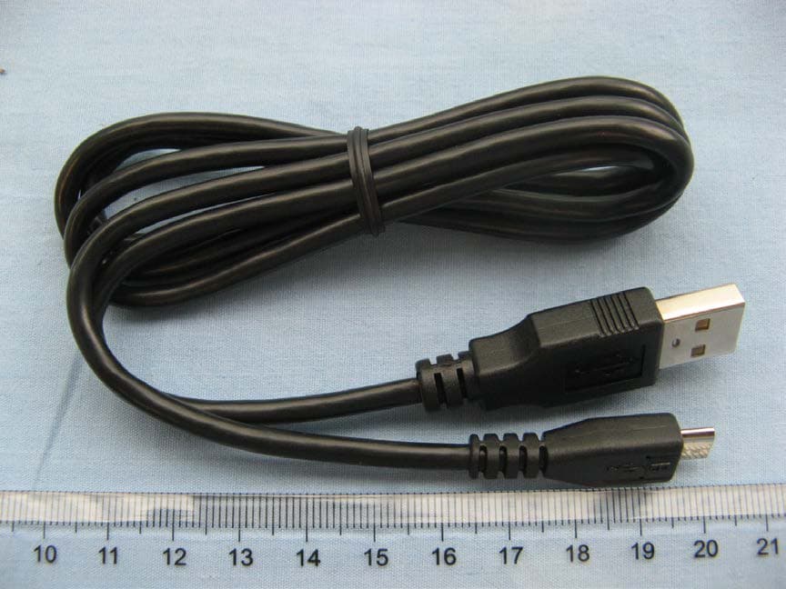
RAD550
Jun 06, 2015HSDPA/HSUPA/HSPA+/UMTS quad band /GSM quad band/LTE 4 band mobile phone
Equipment Class
DSS - Part 15 Spread Spectrum Transmitter
RAD549
May 13, 2015WCDMA tri band / GSM quad band Moblie phone with BT, Wi-Fi functionality.
Equipment Class
DSS - Part 15 Spread Spectrum Transmitter