RAD417HSUPA/HSDPA/UMTS TRIBAND/GSM QUADBAND MOBILE PHONE
TCT Mobile Limited
Click to zoom
Application Details
- Equipment Class
- DTS - Digital Transmission System
- Date of Grant
- Dec 19, 2013
- Application Purpose
- Original Equipment
- Date of Application
- Dec 19, 2013
- Equipment Note
- HSUPA/HSDPA/UMTS TRIBAND/GSM QUADBAND MOBILE PHONE
- Frequency Range
- 2412.00000000 - 2462.00000000
- Company
- TCT Mobile Limited
- Country
- China
Documents & Files
Document Text
Text extracted from the exhibit documents filed with the FCC. Open a document above to read the original.
Users Manual
1 10 2 11 3 12 4 13 5 14 6 15 7 16 89 1817 1 Your mobile ................... 1.1 Keys and connectors • Navigation key Press to go left/right/up/down Press to access function • OK key Press to confirm an option • Volume key Press to adjust volume up/down • Answer/Send a call • Enter Call log • Press: End a call Return to the Home screen • Press and hold: Power on/off • Press and hold: Access your voicemail • Press once: Input a capitalized character • Press twice: Lock the keyboard in capital letter input mode • Press once: Input a top-half character • Press twice: Lock the keyboard in top-half key input mode Fn+ B: Access Bluetooth Fn+ M: Access Music Fn + P: Access Profiles Fn + R: Access Email • Short key press: Enter a space (on edit mode) Unlock the keypad (on Home screen) • Press and hold: Access language list (on edit mode) Lock the keypad (on Home screen) • Hold down Fn key, then press Space key to select input method • Enter symbol table • Hold down Fn key, then press SYM key to enter emotion table • Confirm an option • Enter the next line • Press and hold: Turn on/off vibration alert • Press: Take a picture • Press and hold: Access Camera 1.2 Status bar icons (1) Battery charge level Vibrate alert: your phone vibrates, but does not ring or beep with the exception of the alarm. Bluetooth status (Activated). Bluetooth status (Connected to an audio device). Headset connected. Call forwarding activated: your calls are forwarded. Alarm or appointments programmed. Level of network reception. Voicemail message arrived. Missed calls. Call in progress. Stopwatch is active. Radio is on. Email unread. WAP messages. Roaming. microSD card scanning completed. GPRS connecting. GPRS attached. EDGE connecting. EDGE attached. 3G network connecting. 3G network attached. Wi-Fi connected Wi-Fi disconnected Music active. MMS receipt in progress. Silence mode: your phone does not ring, beep or vibrate with the exception of the alarm. Message unread. (Red) Message list is full: your phone cannot accept any new messages. You must access the message list and delete at least one message on your SIM card. Airplane mode. 1.3 Home screen You can customize your Home screen by selecting ”Personalize” through Right softkey. 1.3.1 Widget bar Widgets are convenient shortcuts for quick access from the Home screen. 1.3.2 Change wallpaper You can select a folder to choose one image as favorite wallpaper by selecting "Change wallpaper". Charging the battery Connect the battery charger to your phone and outlet respectively. To reduce power consumption and energy waste, when battery is fully charged, disconnect your charger from the phone; switch off Bluetooth and running applications in the background when not in use, reduce the backlight time, etc. 2.2 Power on your phone Hold down the key until the telephone powers on. 2.3 Power off your phone Hold down the key from the Home screen. 3 Making a call ................ Dial the desired number then press the key to place the call. The number you entered can be saved to Contacts by selecting "Save". If you make a mistake, you may press key to delete the incorrect digits one by one, or you may press and hold key to delete all. To hang up the call, press the key. 4 Menu arrange .............. It is designed to vary according to your preference. Change the order Access the main menu, focus on the main menu item you want to move, select "Options\Move", and tick "√" will be shown on the item you selected, then release it to your favorite destination. Show/Hide Access the main menu, select "Options\Add and remove menu", and select the left check box of the selected menu once to show/ hide, and then select "Done" to save the operation. 5 Messaging .............. 5.1 Access You may access this menu using the following options: • Access from the main menu by selecting "Messaging". • Select from shortcut bar, and then enter the sub-menu you require. When you access "Messaging", you can switch between SMS/MMS and Email by navigation key. (1) The icons and illustrations in this guide are provided for informational purposes only. (1) The quality of the radio depends on the coverage of the radio station in that particular area. (2) Depending on your network operator and market. 2 Getting started .............. 2.1 Set-up Removing or installing the back cover Inserting or removing the SIM card You must insert your SIM card to make phone calls. Please power off your phone and remove battery before inserting or removing the SIM card. Place the SIM card with the chip facing downwards and slide it into its housing. Make sure that it is correctly inserted. To remove the card, press and slide it out. Installing or removing the battery Insert and click the battery into place, then close the telephone cover. Unclip the cover, then remove the battery. 5.2 Conversational On (Off) mode In conversational on mode, you can view chat history in chronological order. In conversational off mode, you may have access to the following folders: Inbox, Outbox, Sent, Drafts, Voicemail, Broadcast SMS, Empty folder, Archive, Templates, Emergency alerts and Settings. Conversational view mode is set as default. You may switch to conventional mode by selecting "Settings\Switch view mode". The following instructions are based on conversational mode. 5.3 Write message You can select "Messaging\New message" from the main menu or access from shortcut to write text/multimedia message. One or more recipients can be added from contact list and you can remove a recipient by pressing the Delete key. Press the key and select "More" to multi-choice recipients from Contacts. An SMS will be converted to MMS automatically when images, videos, audio, slides or attachments are inserted; Subject, CC/BCC/email address is added; or the message contains more than 8 pages of text. An SMS message of more than a certain number of characters (the number of characters depends on your language) will be charged as several SMS. An MMS message…
Text truncated - open the document above for the full version.
Cover Letter(s)
5F, C building, No. 232, Liang Jing Road ZhangJiang High-Tech Park, Pudong Area Shanghai, P.R. China. 201203 TEL: +86(0)21 61460666 FAX: +86(0)21 61460602 2013-12-13 Federal Communications Commission Office of Engineering and Technology Equipment Authorization Division 7345 Oakland Mills Road Columbia, Maryland 21046 Subject: Permanent Confidentiality request for FCC ID: RAD417 To Whom It May Concern, Pursuant to sections 0.457 and 0.459 of CFR 47, the applicant requests permanent confidential treatment of the following information accompanying this application: - Block Diagram - Schematics - Operational Description - BOM list/Tune-Up-Procedure The above materials contain trade secrets and proprietary information not customarily released to the public. The public disclosure of these matters might be harmful to the applicant and provide unjustified benefits to its competitors. Yours Sincerely, Zhizhou Gong Approval Team Leader TCT Mobile Limited
Cover Letter(s)
5F, C building, No. 232, Liang Jing Road ZhangJiang High-Tech Park, Pudong Area Shanghai, P.R. China. 201203 TEL: +86(0)21 61460666 FAX: +86(0)21 61460602 Date 2013-12-19 To: Federal Communications Commission, Authorization & Evaluation Division, 7345 Oakland Mills Road Columbia, MD 21046 And Timco Engineering, Inc. 849 NW State Road 45 Newberry, Florida 32669 To Whom It May Concern: Song Chongwen from TMC (Telecommunication Metrology Center of MIIT) is authorized to act on our behalf, until otherwise notified, for applications to TIMCO ENGINEERING INC. We certify that we are not subject to denial of federal benefits, which includes FCC benefits, pursuant to Section 5301 of the Anti-Drug Abuse Act of 1988, U.S.C. 862. Further, no party, as defined in 47 CFR1.2002 (b) to the application is subject to denial of federal benefits, that includes FCC benefits. Thank you. Regards, Gong Zhizhou Approval Team Leader TCT Mobile Limited
ID Label/Location Info
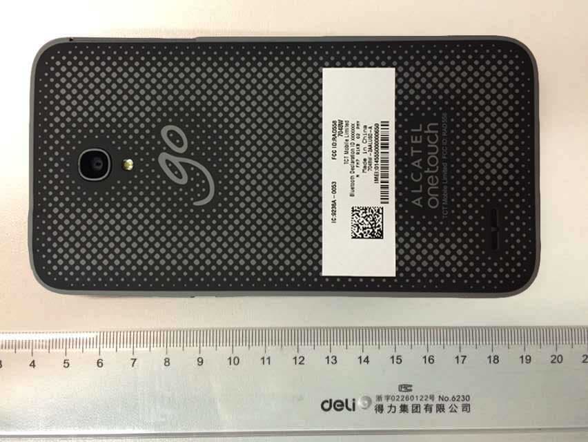
Label location justification letter Because the majority of the transceiver housing is composed of display, speaker, operating controls, and a removable battery pack, there is extremely limited space available to attach the required label carrying the FCC identifier. Attaching the label to the battery pack is not acceptable because the battery pack is a removable item. For this reason, we propose placing the label carrying the FCC identifier inside the battery compartment as shown in figure 2. The consumer packaging for these models includes the battery pack as a separate item, NOT installed on the radio. As such, the FCC identifier will be readily visible to the user before the battery pack is installed and whenever the battery pack is removed or replaced. In this location, the label will also be protected from physical abuse and remain readable for the anticipated life of the device. The consumer packaging for these models is a "gift box" which does not allow the transceiver to be seen at time of purchase. In order to meet the requirements of 47CFR Part 2.925 (d), We will add the FCC identifier "RAD422" to the outside of the consumer "gift box" packaging. To find the label follow these steps: 1. Remove the cover on the rear side of the product 2. Remove the battery 3. The label is located behind the battery
Operational Description
Antenna Details for 3075A WIFI/BT antenna: IFA Gain: -3.4 dBi RF antenna: IFA BAND GSM850 PCS1900 Gain -4.4 dBi -3.9 dBi BAND UMTS5 UMTS2 Gain -4.4 dBi -3.9 dBi
RF Exposure Info
No.2013SAR00150 Page 1 of 118 ©Copyright. All rights reserved by TMC Beijing. SAR TEST REPORT No. 2013SAR00150 For TCT Mobile Limited HSUPA/HSDPA/UMTS dualband / GSM quadband mobile phone Mode Name: Tigris 3G Marketing Name: 3075A With Hardware Version: PIO Software Version: A18 FCC ID: RAD417 Issued Date: 2013-12-09 Note: The test results in this test report relate only to the devices specified in this report. This report shall not be reproduced except in full without the written approval of TMC Beijing. Test Laboratory: TMC Beijing, Telecommunication Metrology Center of MIIT No. 52, Huayuan Bei Road, Haidian District, Beijing, P. R. China 100191. Tel:+86(0)10-62304633-2079, Fax:+86(0)10-62304633 Email:[email protected]. www.emcite.com No. 2013SAR00150 Page 2 of 118 Revision Version Report Number Revision Date Memo 2013SAR00150 00 2013-12-09 Initial creation of test report No. 2013SAR00150 Page 3 of 118 TABLE OF CONTENT 1 TEST LABORATORY .................................................................................................................... 5 1.1 TESTING LO C AT I O N ........................................................................................................................................ 5 1.2 TESTING ENVIRONMENT ................................................................................................................................. 5 1.3 PROJECT DATA ............................................................................................................................................... 5 1.4 SIGNATURE ..................................................................................................................................................... 5 2 STATEMENT OF COMPLIANCE .................................................................................................. 6 3 CLIENT INFORMATION ................................................................................................................ 8 3.1 APPLICANT INFORMATION .............................................................................................................................. 8 3.2 MANUFACTURER INFORMATION ..................................................................................................................... 8 4 EQUIPMENT UNDER TEST (EUT) AND ANCILLARY EQUIPMENT (AE) ................................. 9 4.1 ABOUT EUT ................................................................................................................................................... 9 4.2 INTERNAL IDENTIFICATION OF EUT USED DURING THE TEST .......................................................................... 9 4.3 INTERNAL IDENTIFICATION OF AE USED DURING THE TEST ............................................................................ 9 5 TEST METHODOLOGY .............................................................................................................. 10 5.1 APPLICABLE LIMIT REGULATIONS ................................................................................................................ 10 5.2 APPLICABLE MEASUREMENT STANDARDS .................................................................................................... 10 6 SPECIFIC ABSORPTION RATE (SAR) ...................................................................................... 11 6.1 INTRODUCTION ............................................................................................................................................. 11 6.2 SAR DEFINITION .......................................................................................................................................... 11 7 TISSUE SIMULATING LIQUIDS ................................................................................................. 12 7.1 TARGETS FOR TISSUE SIMULATING LIQUID .................................................................................................... 12 7.2 DIELECTRIC PERFORMANCE ......................................................................................................................... 12 8 SYSTEM VERIFICATION ............................................................................................................ 16 8.1 SYSTEM SETUP ............................................................................................................................................. 16 8.2 SYSTEM VERIFICATION ................................................................................................................................. 17 9 MEASUREMENT PROCEDURES .............................................................................................. 18 9.1 TESTS TO BE PERFORMED ............................................................................................................................. 18 9.2 GENERAL MEASUREMENT PROCEDURE ........................................................................................................ 19 9.3 WCDMA MEASUREMENT PROCEDURES FOR SAR ...................................................................................... 20 9.4 BLUETOOTH & WI-FI MEASUREMENT PROCEDURES FOR SAR .................................................................... 21 9.5 POWER DRIFT ............................................................................................................................................... 21 10 AREA SCAN BASED 1-G SAR ................................................................................................. 22 10.1 REQUIREMENT OF KDB .............................................................................................................................. 22 10.2 FAST SAR ALGORITHMS ............................................................................................................................ 22 11 CONDUCTED OUTPUT POWER .............................................................................................. 23 No. 2013SAR00150 Page 4 of 118 11.1 MAN…
Text truncated - open the document above for the full version.
RF Exposure Info
No. 2013SAR00150 Page 59 of 118 Fig. 7-1 Z-Scan at power reference point (WCDMA1900 CH9262) No. 2013SAR00150 Page 60 of 118 WCDMA 1900 Body Rear Low Date: 2013-10-13 Electronics: DAE4 Sn771 Medium: Body 1900 MHz Medium parameters used (interpolated): f = 1852.4 MHz; σ = 1.493 mho/m; εr = 52.528; ρ = 1000 kg/m 3 Ambient Temperature: 22.6 o C Liquid Temperature: 22.1 o C Communication System: WCDMA 1900 Frequency: 1852.4 MHz Duty Cycle: 1:1 Probe: EX3DV4 - SN3846 ConvF(7.03, 7.03, 7.03) Rear Low/Area Scan (61x101x1): Interpolated grid: dx=1.000 mm, dy=1.000 mm Maximum value of SAR (interpolated) = 1.11 W/kg Rear Low/Zoom Scan (7x7x7)/Cube 0: Measurement grid: dx=5mm, dy=5mm, dz=5mm Reference Value = 12.098 V/m; Power Drift = 0.03 dB Peak SAR (extrapolated) = 1.52 W/kg SAR(1 g) = 0.918 W/kg; SAR(10 g) = 0.529 W/kg Maximum value of SAR (measured) = 1.00 W/kg Fig.8 WCDMA1900 CH9262 No. 2013SAR00150 Page 61 of 118 Fig. 8-1 Z-Scan at power reference point (WCDMA1900 CH9262) No. 2013SAR00150 Page 62 of 118 Wifi 802.11b Left Cheek Channel 11 Date: 2013-11-14 Electronics: DAE4 Sn771 Medium: Head 2450 MHz Medium parameters used (interpolated): f = 2462 MHz; σ = 1.996 mho/m; ε r = 39.974; ρ = 1000 kg/m 3 Ambient Temperature: 22.3 o C Liquid Temperature: 21.8 o C Communication System: WLan 2450 Frequency: 2462 MHz Duty Cycle: 1:1 Probe: E X3DV4 - SN3846 ConvF(6.78, 6.78, 6.78) Cheek Middle/Area Scan (81x131x1): Interpolated grid: dx=1.000 mm, dy=1.000 mm Maximum value of SAR (interpolated) = 0.622 W/kg Cheek Middle/Zoom Scan (7x7x7)/Cube 0: Measurement grid: dx=5mm, dy=5mm, dz=5mm Reference Value = 12.343 V/m; Power Drift = -0.15 dB Peak SAR (extrapolated) = 0.808 W/kg SAR(1 g) = 0.420 W/kg; SAR(10 g) = 0.209 W/kg Maximum value of SAR (measured) = 0.614 W/kg Fig.9 2450 MHz CH11 No. 2013SAR00150 Page 63 of 118 Fig. 9-1 Z-Scan at power reference point (2450 MHz CH11) No. 2013SAR00150 Page 64 of 118 Wifi 802.11b Body Rear Channel 11 Date: 2013-11-14 Electronics: DAE4 Sn771 Medium: Body 2450 MHz Medium parameters used (interpolated): f = 2462 MHz; σ = 1.97 mho/m; ε r = 52.332; ρ = 1000 kg/m 3 Ambient Temperature: 22.3 o C Liquid Temperature: 21.8 o C Communication System: WLan 2450 Frequency: 2462 MHz Duty Cycle: 1:1 Probe: EX3DV4 - SN3846 ConvF(6.73, 6.73, 6.73) Rear Middle/Area Scan (71x111x1): Interpolated grid: dx=1.000 mm, dy=1.000 mm Maximum value of SAR (interpolated) = 0.438 W/kg Rear Middle/Zoom Scan (7x7x7)/Cube 0: Measurement grid: dx=5mm, dy=5mm, dz=5mm Reference Value = 9.933 V/m; Power Drift = -0.11 dB Peak SAR (extrapolated) = 0.556 W/kg SAR(1 g) = 0.298 W/kg; SAR(10 g) = 0.153 W/kg Maximum value of SAR (measured) = 0.438 W/kg Rear Middle/Zoom Scan (7x7x7)/Cube 1: Measurement grid: dx=5mm, dy=5mm, dz=5mm Reference Value = 9.933 V/m; Power Drift = -0.11 dB Peak SAR (extrapolated) = 0.444 W/kg SAR(1 g) = 0.277 W/kg; SAR(10 g) = 0.164 W/kg Maximum value of SAR (measured) = 0.364 W/kg Fig.10 2450 MHz CH11 No. 2013SAR00150 Page 65 of 118 Fig. 10-1 Z-Scan at power reference point (2450 MHz CH11) No. 2013SAR00150 Page 66 of 118 ANNEX B System Verification Results 835MHz Date: 2013-10-12 Electronics: DAE4 Sn771 Medium: Head 850 MHz Medium parameters used: f = 835 MHz; σ = 0.916 mho/m; ε r = 41.86; ρ = 1000 kg/m 3 Ambient Temperature: 22.5 o C Liquid Temperature: 22.0 o C Communication System: CW Frequency: 835 MHz Duty Cycle: 1:1 Probe: EX3DV4 - SN3846 ConvF(8.92, 8.92, 8.92) System Validation/Area Scan (81x161x1): Interpolated grid: dx=1.000 mm, dy=1.000 mm Reference Value = 53.241 V/m; Power Drift = -0.13 dB Fast SAR: SAR(1 g) = 2.33 W/kg; SAR(10 g) = 1.52 W/kg Maximum value of SAR (interpolated) = 2.55 W/kg System Validation/Zoom Scan (7x7x7)/Cube 0: Measurement grid: dx=5mm, dy=5mm, dz=5mm Reference Value = 53.241 V/m; Power Drift = -0.13 dB Peak SAR (extrapolated) = 3.51 W/kg SAR(1 g) = 2.29 W/kg; SAR(10 g) = 1.49 W/kg Maximum value of SAR (measured) = 2.53 W/kg 0 dB = 2.55 W/kg = 8.13 dBW/kg Fig.B.1 validation 835MHz 250mW No. 2013SAR00150 Page 67 of 118 835MHz Date: 2013-10-12 Electronics: DAE4 Sn771 Medium: Body 850 MHz Medium parameters used: f = 835 MHz; σ = 0.964 mho/m; ε r = 56.03; ρ = 1000 kg/m 3 Ambient Temperature: 22.5 o C Liquid Temperature: 22.0 o C Communication System: CW Frequency: 835 MHz Duty Cycle: 1:1 Probe: EX3DV4 - SN3846 ConvF(8.73, 8.73, 8.73) System Validation /Area Scan (81x171x1): Interpolated grid: dx=1.000 mm, dy=1.000 mm Reference Value = 51.633 V/m; Power Drift = 0.10 dB Fast SAR: SAR(1 g) = 2.34 W/kg; SAR(10 g) = 1.55 W/kg Maximum value of SAR (interpolated) = 2.60 W/kg System Validation /Zoom Scan (7x7x7)/Cube 0: Measurement grid: dx=5mm, dy=5mm, dz=5mm Reference Value = 51.633 V/m; Power Drift = 0.10 dB Peak SAR (extrapolated) = 3.42 W/kg SAR(1 g) = 2.38 W/kg; SAR(10 g) = 1.57 W/kg Maximum value of SAR (measured) = 2.62 W/kg 0 dB = 2.60 W/kg = 8.30 dBW/kg Fig.B.2 validation 835MHz 250mW No. 2013SAR00150 Page 68 of 118 1900MHz Date: 2013-10-13 Electronics: DAE4 Sn771 Medium: Head 1900 MHz Medium parameters used: f = 1900 MHz; σ = 1.427 mho/m; ε r = 40.58; ρ = 1000 kg/m 3 Ambient Temperature: 22.6 o C Liquid Temperature: 22.1 o C Communication System: CW Frequency: 1900 MHz Duty Cycle: 1:1 Probe: EX3DV4 - SN3846 ConvF(7.57, 7.57, 7.57) System Validation/Area Scan (81x121x1): Measurement grid: dx=10mm, dy=10mm Reference Value = 96.296 V/m; Power Drift = 0.08 dB Fast SAR: SAR(1 g) = 9.77 W/kg; SAR(10 g) = 5.09 W/kg Maximum value of SAR (interpolated) = 11.5 W/kg System Validation/Zoom Scan (7x7x7)/Cube 0: Measurement grid: dx=5mm, dy=5mm, dz=5mm Reference Value = 96.296 V/m; Power Drift = 0.08 dB Peak SAR (extrapolated) = 17.98 W/kg SAR(1 g) = 9.95 W/kg; SAR(10 g) = 5.24 W/kg Maximum value of SAR (measured) = 11.7 W/kg 0 dB = 11.5 W/kg = 21.21 dB W/kg Fig.B.3 validation 1900MHz 250mW No. 2013SAR00150 Page 69 of 118 1900MHz Date: 2013-10-13 Electronics: DAE4 Sn771 Medium: Body 1900 MHz Medium parameters used: f = 1900 MHz; σ = 1.538 mho/m; ε r = 52.36; ρ = 1000 kg…
Text truncated - open the document above for the full version.
RF Exposure Info
No. 2013SAR00150 Page 99 of 118 No. 2013SAR00150 Page 100 of 118 No. 2013SAR00150 Page 101 of 118 No. 2013SAR00150 Page 102 of 118 No. 2013SAR00150 Page 103 of 118 1900 MHz Dipole Calibration Certificate No. 2013SAR00150 Page 104 of 118 No. 2013SAR00150 Page 105 of 118 No. 2013SAR00150 Page 106 of 118 No. 2013SAR00150 Page 107 of 118 No. 2013SAR00150 Page 108 of 118 No. 2013SAR00150 Page 109 of 118 No. 2013SAR00150 Page 110 of 118 No. 2013SAR00150 Page 111 of 118 2450 MHz Dipole Calibration Certificate No. 2013SAR00150 Page 112 of 118 No. 2013SAR00150 Page 113 of 118 No. 2013SAR00150 Page 114 of 118 No. 2013SAR00150 Page 115 of 118 No. 2013SAR00150 Page 116 of 118 No. 2013SAR00150 Page 117 of 118 No. 2013SAR00150 Page 118 of 118
Test Report
No. 2013WLN0818 Page1 of 93 ©Copyright. All rights reserved by TMC Beijing. FCC PART 15C TEST REPORT No. 2013WLN0818 for TCT Mobile Limited HSUPA/HSDPA/UMTS dual band / GSM quadband mobile phone Model name:Tigris 3G Marketing name: ALCATEL TRIBE 3075A With FCC ID: RAD417 Hardware Version: PIO Software Version: A18 Issued Date: 201 3-12 -19 Note:The test results in this test report relate only to the devices specified in this report. This report shall not be reproduced except in full without the written approval of TMC Beijing. Test Laboratory: TMC Beijing, Telecommunication Metrology Center of Ministry of Industry and Information Technology No. 52 Hua Yuanbei Road, Haidian District, Beijing, P.R.China 100191 Tel:+86(0)10-62304633-2 046, Fax:+86(0)10-62304633-2063 Email:[email protected]. www.emcite.com No. 2013WLN0818 Page2 of 93 ©Copyright. All rights reserved by TMC Beijing. CONTENTS CONTENTS...................................................................................................................................... 2 1. TEST LATORATORY......................................................................................................... 6 1.1. TESTING LOCATION..............................................................................................................6 1.2. PROJECT DATA.....................................................................................................................6 1.3. SIGNATURE..........................................................................................................................6 2. CLIENT INFORMATION.................................................................................................... 7 2.1. APPLICANT INFORMATION..................................................................................................... 7 2.2. MANUFACTURER INFORMATION.............................................................................................7 3. EQUIPMENT UNDER TEST (EUT) AND ANCILLARY EQUIPMENT(AE)......................8 3.1. ABOUT EUT .........................................................................................................................8 3.2. INTERNAL IDENTIFICATION OF EUT USED DURING THE TEST...................................................8 3.3. INTERNAL IDENTIFICATION OF AE USED DURING THE TEST......................................................8 3.4. GENERAL DESCRIPTION....................................................................................................... 8 4. REFERENCE DOCUMENTS............................................................................................9 4.1. DOCUMENTS SUPPLIED BY APPLICANT...................................................................................9 4.2. REFERENCE DOCUMENTS FOR TESTING................................................................................9 5. LABORATORY ENVIRONMENT ......................................................................................9 6. SUMMARY OF TEST RESULTS .....................................................................................10 6.1. SUMMARY OF TEST RESULTS..............................................................................................10 6.2. STATEMENTS......................................................................................................................10 6.3. TEST CONDITIONS..............................................................................................................10 7. TEST EQUIPMENTS UTILIZED .......................................................................................11 ANNEX A: MEASUREMENT RESULTS.......................................................................................12 A.1. MEASUREMENT METHOD....................................................................................................... 12 A.2. MAXIMUM PEAK OUTPUT POWER...........................................................................................13 A.2.1. MAXIMUM PEAK OUTPUT POWER-CONDUCTED.................................................................... 13 A.2.2. MAXIMUM AVERAGE OUTPUT POWER-CONDUCTED..............................................................14 A.3. PEAK POWER SPECTRAL DENSITY.........................................................................................15 A.4. OCCUPIED 6DB BANDWIDTH.................................................................................................. 16 FIG. 1 OCCUPIED 6DB BANDWIDTH (802.11B, CH 1) ................................................................. 17 FIG. 2 OCCUPIED 6DB BANDWIDTH (802.11B, CH 6) ................................................................. 17 FIG. 3 OCCUPIED 6DB BANDWIDTH (802.11 B, CH 11) ...............................................................18 FIG. 4 OCCUPIED 6DB BANDWIDTH (802.11G, CH 1) ................................................................. 18 FIG. 5 OCCUPIED 6DB BANDWIDTH (802.11G, CH 6) ................................................................. 19 FIG. 6 OCCUPIED 6DB BANDWIDTH (802.11G, CH 11) ...............................................................19 FIG. 7 OCCUPIED 6DB BANDWIDTH (802.11N-HT20, CH 1) .......................................................20 FIG. 8 OCCUPIED 6DB BANDWIDTH (802.11N-HT20, CH 6) .......................................................20 No. 2013WLN0818 Page3 of 93 ©Copyright. All rights reserved by TMC Beijing. FIG. 9 OCCUPIED 6DB BANDWIDTH (802.11N-HT20, CH 11) .....................................................21 A.5. BAND EDGES COMPLIANCE.................................................................................................... 22 FIG. 10 BAND EDGES (802.11B, CH 1) ........................................................................................23 FIG. 11 BAND EDGES (802.11B, CH 11) ......................................................................................23 FIG. 12 BAND EDGES (802.11G, CH 1) .........................…
Text truncated - open the document above for the full version.
Test Setup Photos
EUT Set-up photos
Test Setup Photos
©Copyright. All rights reserved by TMC Beijing. The Photos of SAR test No. 2013SAR00150 For TCT Mobile Limited HSUPA/HSDPA/UMTS dualband / GSM quadband mobile phone Mode Name: Tigris 3G Marketing Name: 3075A With Hardware Version: PIO Software Version: A18 FCC ID: RAD417 Issued Date: 2013-12-09 Note: The test results in this test report relate only to the devices specified in this report. This report shall not be reproduced except in full without the written approval of TMC Beijing. Test Laboratory: TMC Beijing, Telecommunication Metrology Center of MIIT No. 52, Huayuan Bei Road, Haidian District, Beijing, P. R. China 100191. Tel:+86(0)10-62304633-2079, Fax:+86(0)10-62304633 Email:[email protected]. www.emcite.com Picture 1: Constituents of the sample Picture 2: Left Hand Touch Cheek Position Picture 3: Left Hand Tilt 15° Position Picture 4: Right Hand Touch Cheek Position Picture 5: Right Hand Tilt 15° Position Test positions for body: The Body SAR is tested at the following 6 test positions all with the distance =10mm between the EUT and the phantom bottom: Picture 6: Front Picture 7: Rear Picture 7-1: Rear with Headset Picture 8: Left Edge Picture 9: Right Edge Picture 10: Bottom Edge Picture 11: Top Edge
Contact Information
Applicant
Zhizhou Gong
Test Firm
TMC-Telecommunication Metrology Center of M.I.I.TChongwen Song
Technical Specifications
| # | Rule Parts | Frequency Range | Power Output |
|---|---|---|---|
| 1 | 15C | 2.41 GHz - 2.46 GHz | 142.90 mW |
Other Applications from TCT Mobile Limited
RAD558
Nov 15, 2015HSUPA/HSDPA/UMTS tribands / GSM quadbands/LTE 6-band mobile phone
Equipment Class
JBP - Part 15 Class B Computing Device Peripheral
RAD556
Sep 08, 2015CDMA 1X BC0/BC1/BC10 mobile phone
Equipment Class
PCE - PCS Licensed Transmitter held to ear
RAD552
Jun 20, 2015GSM Quadband / UMTS Triband mobile phone
Equipment Class
PCE - PCS Licensed Transmitter held to ear
RAD550
Jun 06, 2015HSDPA/HSUPA/HSPA+/UMTS quad band /GSM quad band/LTE 4 band mobile phone
Equipment Class
DSS - Part 15 Spread Spectrum Transmitter
RAD549
May 13, 2015WCDMA tri band / GSM quad band Moblie phone with BT, Wi-Fi functionality.
Equipment Class
DSS - Part 15 Spread Spectrum Transmitter