RAD515HSUPA/HSDPA/UMTS dual-band/GSM quad-band mobile phone
TCT Mobile Limited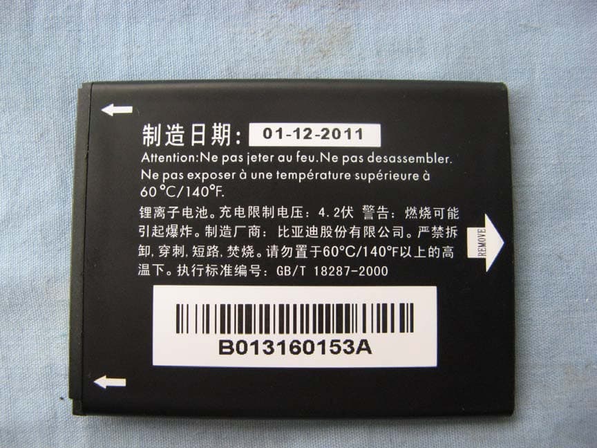
Click to zoom
Application Details
- Equipment Class
- PCE - PCS Licensed Transmitter held to ear
- Date of Grant
- Aug 12, 2014
- Application Purpose
- Original Equipment
- Date of Application
- Aug 11, 2014
- Equipment Note
- HSUPA/HSDPA/UMTS dual-band/GSM quad-band mobile phone
- Frequency Range
- 826.40000000 - 846.60000000
- Company
- TCT Mobile Limited
- Country
- China
Documents & Files
Document Text
Text extracted from the exhibit documents filed with the FCC. Open a document above to read the original.
Users Manual
12 English - CJB27J5ALAAA Quick Start Guide For more information about how to use the phone, please go to www.alcatelonetouch.com to download the complete user manual. Also on our website you can find helpful FAQs, perform software upgrades, etc. www.sar-tick.com This product meets applicable national SAR limits of 1.6 W/kg. The specific maximum SAR values can be found in the RADIOWAVES section of this user guide. When carrying the product or using it while worn on your body, either use an approved accessory such as a holster or otherwise maintain a distance of 10 mm from the body to ensure compliance with RF exposure requirements. Note that the product may be transmitting even if you are not making a phone call. PROTECT YOUR HEARING To prevent possible hearing damage, do not listen at high volume levels for long periods. Exercise caution when holding your device near your ear while the loudspeaker is in use. 1 Your mobile .................. 1.1 Keys and connectors Headset connector Power key micro-USB connector Back key Home key Menu key Touch screen 34 Volume up Volume down Camera Microphone Menu key • Option menu. Touch to access Manage Home- screen, Add widgets, Manage applications, Wallpaper and Settings. • Recent apps. Touch and hold to open a list of thumbnail images of apps you've worked with recently. Touch it to open an app. Swipe it left or right to remove a thumbnail from the list. Home key • While on any application or screen, touch to return to the Home screen. Back key • Touch to go back to the previous screen, or to close a dialog box, options menu, the notification panel, etc. Power key • Press: Lock the screen/Light up the screen. • Press and hold: Power on or generate a pop up menu selecting from Power off/Restart/Airplane mode or icons of Ringer mode. • Press to mute the ringtone when there’s an incoming call. • Press and hold for more than 7 seconds to restart the phone when the system stops responding. • Press and hold Power key and Volume down key to capture a screenshot. • Press and hold Power key and Volume up key under power off mode to restore factory set. Volume keys • Under call mode, adjust the earpiece or headset volume. • In Music/Video/Streaming mode, adjust the media volume. • In general mode, adjust the ring tone volume. • Mute the ringtone of an incoming call. • In Camera mode, using it as the capture key allows you to take a photo. 56 1.2 Getting started 1.2.1 Set-up Removing or installing the back cover Inserting or removing the SIM card You must insert your SIM card to make phone calls. Please power off your phone before inserting or removing the SIM card. Place the SIM card with the chip facing downwards and slide it into its housing. Make sure that it is correctly inserted. To remove the card, press and slide it out. Your phone only supports mini-SIM card. Do not attempt to insert other SIM types like micro and nano cards, otherwise you may damage your phone. Installing or removing the battery Please power off your phone before removing the battery. • Insert and click the battery into place, then close the cover. • Unclip the cover, then remove the battery. Installing the microSD card To install, please open microSD card lock first, and then place the external microSD card into the slot with the gold contact facing down. To remove the external microSD card, please open microSD card lock and take it out from the slot. Charging the battery Connect the battery charger to your phone and outlet respectively. If the battery is very low, there will be no indication that power is being received until the charge is sufficient enough to show the charging status bar. To reduce power consumption and energy waste, once the battery is fully charged, disconnect your charger from the plug; switch off Wi-Fi, GPS, Bluetooth or applications running in the background when not in use; reduce the backlight time, etc. 78 1.2.2 Power on your phone Hold down the Power key until the phone powers on. It will take a few seconds before the screen lights up. Set up your phone for the first time The first time you power on the phone, you should set the following options: language, input method, date & time, Google account, etc. If you power on your phone with no SIM card inserted, you can connect to a Wi-Fi network to sign into your Google account and to use some features. 1.2.3 Power off your phone Hold down the Power key until the Phone options appear, select Power off. 1.3 Home screen You can bring all the items (applications, shortcuts, folders and widgets) you use most frequently to your Home screen for quick access. Touch the Home key to switch to Home screen. Status bar • Status/Notification indicators • Touch and drag down to open the notification panel. Application tab • Touch to open main menu. Search bar (1) • Touch to enter text search screen. • Touch to enter voice search screen. Favorite applications tray • Touch to enter the application. • Touch and hold to move or change applications. Add a location to display local weather. Home screen is provided in an extended format to allow more space for adding applications, shortcuts etc. Slide the Home screen horizontally left and right to get a complete view of the Home screen. The row of small squares at the lower part of the screen indicates which screen you are viewing. 1.3.1 Using the touchscreen Touch To access an application, touch it with your finger. Touch and Hold Touch and hold the home screen to get the widgets. Drag Place your finger on any item to drag it to another location. Slide/Swipe Slide the screen to scroll up and down the applications, images, web pages... at your convenience. Flick Similar to swiping, but flicking makes it move quicker. Pinch/Spread Place your fingers of one hand on the screen surface and draw them apart or together to scale an element on the screen. Rotate Automatically change the screen orientation from portrait to landscape by turning the phone sideways to have a better view…
Text truncated - open the document above for the full version.
Cover Letter(s)
5F, C building, No. 232, Liang Jing Road ZhangJiang High-Tech Park, Pudong Area Shanghai, P.R. China. 201203 TEL: +86(0)21 61460666 FAX: +86(0)21 61460602 Date 2014-08-01 To: Federal Communications Commission, Authorization & Evaluation Division, 7345 Oakland Mills Road Columbia, MD 21046 And American Telecommunications Certification Body, Inc. 6731 Whittier Avenue Suite C110 McLean, VA 22101 To Whom It May Concern: TMC (Telecommunication Metrology Center of MIIT) is authorized to act on our behalf, until otherwise notified, for applications to American Telecommunications Certification Body, Inc. (ATCB). We certify that we are not subject to denial of federal benefits, which includes FCC benefits, pursuant to Section 5301 of the Anti-Drug Abuse Act of 1988, U.S.C. 862. Further, no party, as defined in 47 CFR1.2002 (b) to the application is subject to denial of federal benefits, that includes FCC benefits. Thank you. Regards, Gong Zhizhou Approval Team Leader TCT Mobile Limited
Cover Letter(s)
5F, C building, No. 232, Liang Jing Road ZhangJiang High-Tech Park, Pudong Area Shanghai, P.R. China. 201203 TEL: +86(0)21 61460666 FAX: +86(0)21 61460602 08/01/2014 Federal Communications Commission Office of Engineering and Technology Equipment Authorization Division 7345 Oakland Mills Road Columbia, Maryland 21046 Subject: Permanent Confidentiality request for FCC ID: RAD515 To Whom It May Concern, Pursuant to sections 0.457 and 0.459 of CFR 47, the applicant requests permanent confidential treatment of the following information accompanying this application: - Block Diagram - Schematics - Operational Description - BOM list/Tune-Up-Procedure The above materials contain trade secrets and proprietary information not customarily released to the public. The public disclosure of these matters might be harmful to the applicant and provide unjustified benefits to its competitors. Yours Sincerely, Zhizhou Gong Approval Team Leader TCT Mobile Limited
External Photos
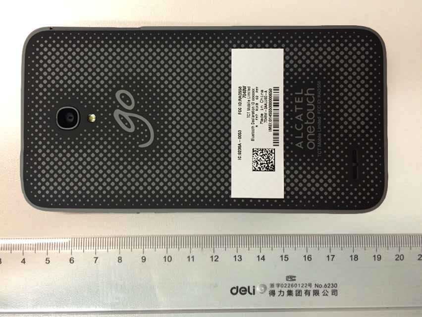
EUT photograph Mobile Phone Mobile Phone Mobile Phone Mobile Phone Mobile Phone Mobile Phone Mobile Phone Battery AE1 Battery AE1 Battery AE2 Battery AE2 Battery AE3 Battery AE3 Battery AE5 Battery AE5 Battery AE6 Battery AE6 Charger AE7 Label of Charger AE7 Charger AE8 Label of Charger AE8 Headset AE10 Headset AE11 Headset AE12 Headset AE13 Headset AE14 Headset AE15 Headset AE16 Headset AE17 Headset AE18 Data Cable AE19 Data Cable AE20 Data Cable AE21 Data Cable AE22
Internal Photos
EUT Interior photograph Mobile Phone Mobile Phone Disassembly Mobile Phone Disassembly Mobile Phone Disassembly
RF Exposure Info
No.I14Z47396-SEM01 Page 1 of 113 ©Copyright. All rights reserved by TMC Beijing. SAR TEST REPORT No. I14Z47396-SEM01 For TCT Mobile Limited HSUPA/HSDPA/UMTS dual band/GSM quad-band mobile phone Model Name: 4018M With Hardware Version: PIO Software Version: v8I1F FCC ID: RAD515 Issued Date: 2014-08-01 Note: The test results in this test report relate only to the devices specified in this report. This report shall not be reproduced except in full without the written approval of TMC Beijing. Test Laboratory: TMC Beijing, Telecommunication Metrology Center of MIIT No. 52, Huayuan Bei Road, Haidian District, Beijing, P. R. China 100191. Tel:+86(0)10-62304633-2079, Fax:+86(0)10-62304633 Email:[email protected]. www.emcite.com No. I14Z47396-SEM01 Page 2 of 113 Revision Version Report Number Revision Date Memo I14Z47396-SEM01 0 2014-08-01 Initial creation of test report No. I14Z47396-SEM01 Page 3 of 113 TABLE OF CONTENT 1 TEST LABORATORY .................................................................................................................... 5 1.1 TESTING LO C AT I O N ........................................................................................................................................ 5 1.2 TESTING ENVIRONMENT ................................................................................................................................. 5 1.3 PROJECT DATA ............................................................................................................................................... 5 1.4 SIGNATURE ..................................................................................................................................................... 5 2 STATEMENT OF COMPLIANCE .................................................................................................. 6 3 CLIENT INFORMATION ................................................................................................................ 8 3.1 APPLICANT INFORMATION .............................................................................................................................. 8 3.2 MANUFACTURER INFORMATION ..................................................................................................................... 8 4 EQUIPMENT UNDER TEST (EUT) AND ANCILLARY EQUIPMENT (AE) ................................. 9 4.1 ABOUT EUT ................................................................................................................................................... 9 4.2 INTERNAL IDENTIFICATION OF EUT USED DURING THE TEST .......................................................................... 9 4.3 INTERNAL IDENTIFICATION OF AE USED DURING THE TEST .......................................................................... 10 5 TEST METHODOLOGY .............................................................................................................. 11 5.1 APPLICABLE LIMIT REGULATIONS ................................................................................................................ 11 5.2 APPLICABLE MEASUREMENT STANDARDS .................................................................................................... 11 6 SPECIFIC ABSORPTION RATE (SAR) ...................................................................................... 12 6.1 INTRODUCTION ............................................................................................................................................. 12 6.2 SAR DEFINITION .......................................................................................................................................... 12 7 TISSUE SIMULATING LIQUIDS ................................................................................................. 13 7.1 TARGETS FOR TISSUE SIMULATING LIQUID .................................................................................................... 13 7.2 DIELECTRIC PERFORMANCE ......................................................................................................................... 13 8 SYSTEM VERIFICATION ............................................................................................................ 17 8.1 SYSTEM SETUP ............................................................................................................................................. 17 8.2 SYSTEM VERIFICATION ................................................................................................................................. 18 9 MEASUREMENT PROCEDURES .............................................................................................. 19 9.1 TESTS TO BE PERFORMED ............................................................................................................................. 19 9.2 GENERAL MEASUREMENT PROCEDURE ........................................................................................................ 20 9.3 WCDMA MEASUREMENT PROCEDURES FOR SAR ...................................................................................... 21 9.4 BLUETOOTH & WI-FI MEASUREMENT PROCEDURES FOR SAR .................................................................... 22 9.5 POWER DRIFT ............................................................................................................................................... 22 10 AREA SCAN BASED 1-G SAR ................................................................................................. 23 10.1 REQUIREMENT OF KDB .............................................................................................................................. 23 10.2 FAST SAR ALGORITHMS ............................................................................................................................ 23 11 CONDUCTED OUTPUT POWER .............................................................................................. 24 No. I14Z47396-SEM01 Page 4 of 113 11.1 MANUFACTUR…
Text truncated - open the document above for the full version.
RF Exposure Info
No. I14Z47396-SEM01 Page 57 of 113 Wifi 802.11b Left Cheek Channel 11 Date: 2014- 5- 24 Electronics: DAE4 Sn771 Medium: Head 2450 MHz Medium parameters used (interpolated): f = 2462 MHz; σ = 1.845 S/m; ε r = 38.641; ρ = 1000 kg/m 3 Ambient Temperature: 22.2 o C Liquid Temperature: 21.7 o C Communication System: WLan 2450 Frequency: 2462 MHz Duty Cycle: 1:1 Probe: EX3DV4 - SN3846 ConvF(6.78, 6.78, 6.78) Cheek High/Area Scan (61x81x1): Interpolated grid: dx=1.000 mm, dy=1.000 mm Maximum value of SAR (interpolated) = 0.224 W/kg Cheek High/Zoom Scan (7x7x7)/Cube 0: Measurement grid: dx=5mm, dy=5mm, dz=5mm Reference Value = 7.847 V/m; Power Drift = 0.03 dB Peak SAR (extrapolated) = 0.440 W/kg SAR(1 g) = 0.192 W/kg; SAR(10 g) = 0.092 W/kg Maximum value of SAR (measured) = 0.222 W/kg Fig.7 2450 MHz CH11 No. I14Z47396-SEM01 Page 58 of 113 Fig. 7-1 Z-Scan at power reference point (2450 MHz CH11) No. I14Z47396-SEM01 Page 59 of 113 Wifi 802.11b Body Rear Channel 11 Date: 2014- 5- 24 Electronics: DAE4 Sn771 Medium: Body 2450 MHz Medium parameters used (interpolated): f = 2462 MHz; σ = 1.942 S/m; ε r = 52.036; ρ = 1000 kg/m 3 Ambient Temperature: 22.2 o C Liquid Temperature: 21.7 o C Communication System: WLan 2450 Frequency: 2462 MHz Duty Cycle: 1:1 Probe: EX3DV4 - SN3846 ConvF(6.73, 6.73, 6.73) Rear High/Area Scan (61x91x1): Interpolated grid: dx=1.000 mm, dy=1.000 mm Maximum value of SAR (interpolated) = 0.156 W/kg Rear High/Zoom Scan (7x7x7)/Cube 0: Measurement grid: dx=5mm, dy=5mm, dz=5mm Reference Value = 3.422 V/m; Power Drift = 0.17 dB Peak SAR (extrapolated) = 0.253 W/kg SAR(1 g) = 0.129 W/kg; SAR(10 g) = 0.065 W/kg Maximum value of SAR (measured) = 0.141 W/kg Fig.8 2450 MHz CH11 No. I14Z47396-SEM01 Page 60 of 113 Fig. 8-1 Z-Scan at power reference point (2450 MHz CH11) No. I14Z47396-SEM01 Page 61 of 113 ANNEX B System Verification Results 835MHz Date: 2014- 7- 22 Electronics: DAE4 Sn771 Medium: Head 850 MHz Medium parameters used: f = 835 MHz; σ = 0.909 S/m; ε r = 42.11; ρ = 1000 kg/m 3 Ambient Temperature: 22.4 o C Liquid Temperature: 21.9 o C Communication System: CW Frequency: 835 MHz Duty Cycle: 1:1 Probe: EX3DV4 - SN3846 ConvF(8.92, 8.92, 8.92) System Validation/Area Scan (81x161x1): Interpolated grid: dx=1.000 mm, dy=1.000 mm Reference Value = 54.004 V/m; Power Drift = 0.05 dB Fast SAR: SAR(1 g) = 2.42 W/kg; SAR(10 g) = 1.58 W/kg Maximum value of SAR (interpolated) = 2.63 W/kg System Validation/Zoom Scan (7x7x7)/Cube 0: Measurement grid: dx=5mm, dy=5mm, dz=5mm Reference Value = 54.004 V/m; Power Drift = 0.05 dB Peak SAR (extrapolated) = 3.59 W/kg SAR(1 g) = 2.37 W/kg; SAR(10 g) = 1.55 W/kg Maximum value of SAR (measured) = 2.61 W/kg 0 dB = 2.63 W/kg = 8.40 dBW/kg Fig.B.1 validation 835MHz 250mW No. I14Z47396-SEM01 Page 62 of 113 835MHz Date: 2014- 7- 22 Electronics: DAE4 Sn771 Medium: Body 850 MHz Medium parameters used: f = 835 MHz; σ = 0.963 S/m; ε r = 56.4; ρ = 1000 kg/m 3 Ambient Temperature: 22.4 o C Liquid Temperature: 21.9 o C Communication System: CW Frequency: 835 MHz Duty Cycle: 1:1 Probe: EX3DV4 - SN3846 ConvF(8.73, 8.73, 8.73) System Validation /Area Scan (81x171x1): Interpolated grid: dx=1.000 mm, dy=1.000 mm Reference Value = 50.849 V/m; Power Drift = -0.08 dB Fast SAR: SAR(1 g) = 2.26 W/kg; SAR(10 g) = 1.48 W/kg Maximum value of SAR (interpolated) = 2.51 W/kg System Validation /Zoom Scan (7x7x7)/Cube 0: Measurement grid: dx=5mm, dy=5mm, dz=5mm Reference Value = 50.849 V/m; Power Drift = -0.08 dB Peak SAR (extrapolated) = 3.33 W/kg SAR(1 g) = 2.3 W/kg; SAR(10 g) = 1.51 W/kg Maximum value of SAR (measured) = 2.54 W/kg 0 dB = 2.51 W/kg = 7.99 dBW/kg Fig.B.2 validation 835MHz 250mW No. I14Z47396-SEM01 Page 63 of 113 1900MHz Date: 2014- 7- 23 Electronics: DAE4 Sn771 Medium: Head 1900 MHz Medium parameters used: f = 1900 MHz; σ = 1.415 S/m; ε r = 39.55; ρ = 1000 kg/m 3 Ambient Temperature: 22.4 o C Liquid Temperature: 21.9 o C Communication System: CW Frequency: 1900 MHz Duty Cycle: 1:1 Probe: EX3DV4 - SN3846 ConvF(7.57, 7.57, 7.57) System Validation/Area Scan (81x121x1): Interpolated grid: dx=1.000 mm, dy=1.000 mm Reference Value = 98.813 V/m; Power Drift = 0.04 dB Fast SAR: SAR(1 g) = 10.0 W/kg; SAR(10 g) = 5.25 W/kg Maximum value of SAR (interpolated) = 11.8 W/kg System Validation/Zoom Scan (7x7x7)/Cube 0: Measurement grid: dx=5mm, dy=5mm, dz=5mm Reference Value = 98.813 V/m; Power Drift = 0.04 dB Peak SAR (extrapolated) = 18.25 W/kg SAR(1 g) = 10.2 W/kg; SAR(10 g) = 5.4 W/kg Maximum value of SAR (measured) = 12.0 W/kg 0 dB = 11.8 W/kg = 21.44 dB W/kg Fig.B.3 validation 1900MHz 250mW No. I14Z47396-SEM01 Page 64 of 113 1900MHz Date: 2014- 7- 23 Electronics: DAE4 Sn771 Medium: Body 1900 MHz Medium parameters used: f = 1900 MHz; σ = 1.496 S/m; ε r = 54.09; ρ = 1000 kg/m 3 Ambient Temperature: 22.4 o C Liquid Temperature: 21.9 o C Communication System: CW Frequency: 1900 MHz Duty Cycle: 1:1 Probe: EX3DV4 - SN3846 ConvF(7.03, 7.03, 7.03) System Validation/Area Scan (81x121x1): Interpolated grid: dx=1.000 mm, dy=1.000 mm Reference Value = 78.697 V/m; Power Drift = -0.09 dB Fast SAR: SAR(1 g) = 10.0 W/kg; SAR(10 g) = 5.22 W/kg Maximum value of SAR (interpolated) = 11.6 W/kg System Validation/Zoom Scan (7x7x7)/Cube 0: Measurement grid: dx=5mm, dy=5mm, dz=5mm Reference Value = 78.697 V/m; Power Drift = -0.09 dB Peak SAR (extrapolated) = 16.65 W/kg SAR(1 g) = 10.2 W/kg; SAR(10 g) = 5.39 W/kg Maximum value of SAR (measured) = 11.8 W/kg 0 dB = 11.6 W/kg = 21.29 dB W/kg Fig.B.4 validation 1900MHz 250mW No. I14Z47396-SEM01 Page 65 of 113 2450MHz Date: 2014- 5- 24 Electronics: DAE4 Sn771 Medium: Head 2450 MHz Medium parameters used: f = 2450 MHz; σ = 1.833 S/m; ε r = 38.72; ρ = 1000 kg/m 3 Ambient Temperature: 22.2 o C Liquid Temperature: 21.7 o C Communication System: CW Frequency: 2450 MHz Duty Cycle: 1:1 Probe: EX3DV4 - SN3846 ConvF(6.78, 6.78, 6.78) System Validation /Area Scan (81x101x1): Measurement grid: dx=10mm, dy=10mm Reference Value = 91.891 V/m; Power Drift = -0.06 dB Fast SA…
Text truncated - open the document above for the full version.
RF Exposure Info
No. I14Z47396-SEM01 Page 85 of 113 No. I14Z47396-SEM01 Page 86 of 113 No. I14Z47396-SEM01 Page 87 of 113 No. I14Z47396-SEM01 Page 88 of 113 No. I14Z47396-SEM01 Page 89 of 113 No. I14Z47396-SEM01 Page 90 of 113 ANNEX H Dipole Calibration Certificate 835 MHz Dipole Calibration Certificate No. I14Z47396-SEM01 Page 91 of 113 No. I14Z47396-SEM01 Page 92 of 113 No. I14Z47396-SEM01 Page 93 of 113 No. I14Z47396-SEM01 Page 94 of 113
RF Exposure Info
No. I14Z47396-SEM01 Page 95 of 113 No. I14Z47396-SEM01 Page 96 of 113 No. I14Z47396-SEM01 Page 97 of 113 No. I14Z47396-SEM01 Page 98 of 113 1900 MHz Dipole Calibration Certificate No. I14Z47396-SEM01 Page 99 of 113 No. I14Z47396-SEM01 Page 100 of 113 No. I14Z47396-SEM01 Page 101 of 113 No. I14Z47396-SEM01 Page 102 of 113 No. I14Z47396-SEM01 Page 103 of 113 No. I14Z47396-SEM01 Page 104 of 113 No. I14Z47396-SEM01 Page 105 of 113 No. I14Z47396-SEM01 Page 106 of 113 2450 MHz Dipole Calibration Certificate No. I14Z47396-SEM01 Page 107 of 113 No. I14Z47396-SEM01 Page 108 of 113 No. I14Z47396-SEM01 Page 109 of 113 No. I14Z47396-SEM01 Page 110 of 113 No. I14Z47396-SEM01 Page 111 of 113 No. I14Z47396-SEM01 Page 112 of 113 No. I14Z47396-SEM01 Page 113 of 113
Test Report
No. I14Z47396-SEM02 Page 1 of 85 ©Copyright. All rights reserved by TMC Beijing. HAC RF TEST REPORT No. I14Z47396-SEM02 For TCT Mobile Limited HSUPA/HSDPA/UMTS dua l-band/GSM quad-band mobile phone Model Name: 4018M With Hardware Version: PIO Software Version: v8I1F FCC ID: RAD515 Results Summary: M Category = M3 Issued Date: 2014-08-04 Note: The test results in this test report relate only to the devices specified in this report. This report shall not be reproduced except in full without the written approval of TMC Beijing. Test Laboratory: TMC Beijing, Telecommunication Metrology Center of MIIT No. 52, Huayuan Bei Road, Haidian District, Beijing, P. R. China 100191. Te l:+86(0)10-62304633-2079, Fax:+86(0)10-62304793 Email:[email protected]. www.emcite.com Revision Version Report Number Revision Date Memo I14Z47396-SEM02 0 2014-08-04 Initial creation of test report No. I14Z47396-SEM02 Page 3 of 85 TABLE OF CONTENT 1 TEST LABORATORY ................................................................................................................... 4 1.1 TESTING LO C AT I O N ........................................................................................................................................ 4 1.2 TESTING ENVIRONMENT ................................................................................................................................. 4 1.3 PROJECT DATA ............................................................................................................................................... 4 1.4 SIGNATURE ..................................................................................................................................................... 4 2 CLIENT INFORMATION ............................................................................................................... 5 2.1 APPLICANT INFORMATION .............................................................................................................................. 5 2.2 MANUFACTURER INFOR M AT I O N ..................................................................................................................... 5 3 EQUIPMENT UNDER TEST (EUT) AND ANCILLARY EQUIPMENT (AE) ................................ 6 3.1 ABOUT EUT ................................................................................................................................................... 6 3.2 INTERNAL IDENTIFICATION OF EUT USED DURING THE TEST .......................................................................... 6 3.3 INTERNAL IDENTIFICATION OF AE USED DURING THE TEST ............................................................................ 6 3.4 AIR INTERFACES / BANDS INDICATING OPERATING MODES ............................................................................ 6 4 CONDUCTED OUTPUT POWER MEASUREMENT ................................................................... 7 4.1 SUMMARY ...................................................................................................................................................... 7 4.2 CONDUCTED POWER ...................................................................................................................................... 7 5. REFERENCE DOCUMENTS ....................................................................................................... 7 5.1REFERENCE DOCUMENTS FOR TESTING ........................................................................................................... 7 6 OPERATIONAL CONDITIONS DURING TEST ........................................................................... 8 6.1 HAC MEASUREMENT SET-UP .................................................................................................................. 8 6.2 PROBE SPECIFICATION .................................................................................................................................... 9 6.3 TEST ARCH PHANTOM & PHONE POSITIONER............................................................................................... 10 6.4 ROBOTIC SYSTEM SPECIFICATIONS .............................................................................................................. 10 7 EUT ARRANGEMENT ................................................................................................................. 11 7.1 WD RF EMISSION MEASUREMENTS REFERENCE AND PLANE ...................................................................... 11 8 SYSTEM VALIDATION ............................................................................................................... 12 8.1 VALIDATION PROCEDURE ............................................................................................................................. 12 8.2 VALIDATION RE S U LT .................................................................................................................................... 12 9 PROBE MODULATION FACTOR............................................................................................... 13 9.1 MODULATION FACTOR TEST PROCEDURE ..................................................................................................... 13 9.2 MODULATION FACTOR.................................................................................................................................. 14 10 RF TEST PROCEDUERES ...................................................................................................... 15 11 HAC RF TEST DATA SUMMARY ............................................................................................. 16 11.1 MEASUREMENT RESULTS (E-FIELD) ........................................................................................................... 16 11.2 MEASUREMENT RESULTS (H-FIELD) .......................................................................................................... 16 11.3 TOTAL M-R AT I N G ..........................................................................…
Text truncated - open the document above for the full version.
Test Report
No. I14Z47396-SEM02 Page 66 of 85 No. I14Z47396-SEM02 Page 67 of 85 No. I14Z47396-SEM02 Page 68 of 85 No. I14Z47396-SEM02 Page 69 of 85 ANNEX E DIPOLE CALIBRATION CERTIFICATE Dipole 835 MHz No. I14Z47396-SEM02 Page 70 of 85 No. I14Z47396-SEM02 Page 71 of 85 No. I14Z47396-SEM02 Page 72 of 85 No. I14Z47396-SEM02 Page 73 of 85 No. I14Z47396-SEM02 Page 74 of 85 No. I14Z47396-SEM02 Page 75 of 85 No. I14Z47396-SEM02 Page 76 of 85 No. I14Z47396-SEM02 Page 77 of 85 Dipole 1880 MHz No. I14Z47396-SEM02 Page 78 of 85 No. I14Z47396-SEM02 Page 79 of 85 No. I14Z47396-SEM02 Page 80 of 85 No. I14Z47396-SEM02 Page 81 of 85 No. I14Z47396-SEM02 Page 82 of 85 No. I14Z47396-SEM02 Page 83 of 85 No. I14Z47396-SEM02 Page 84 of 85 No. I14Z47396-SEM02 Page 85 of 85 The photos of HAC test are presented in the additional document: Appendix to test report no. I14Z47396-SEM02 The photos of HAC test
Test Report
No. I14Z47396-GTE01 Page1 of 76 TEST REPORT No. I14Z47396-GTE01 for TCT Mobile Limited HSUPA/HSDPA/UMTS dual-band/GSM quad-band mobile phone Model Name: 4018M with Hardware Version: PIO Software Version: v8I1F Issued Date: 2014-08-01 Note: The test results in this test report relate only to the devices specified in this report. This report shall not be reproduced except in full without the written approval of TMC Beijing. Test Laboratory: DAR accreditation (DIN EN ISO/IEC 17025): No. D-PL-12123-01-01 FCC 2.948 Listed: No.733176 IC O.A.T.S listed: No.6629B T TMC Beijing, Telecommunication Metrology Center of Ministry of Industry and Information Technology No.51 XueYuan Road,HaiDian District,Beijing,China Tel: +86(0)10-62304633-2561, Fax: +86(0)10-62304633-2504 Email:[email protected]. www.emcite.com No. I14Z47396-GTE01 Page2 of 76 CONTENTS 1. TEST LABORATORY ......................................................................................................................... 3 1.1. TESTING LOCATION .................................................................................................................... 3 1.2. TESTING ENVIRONMENT ........................................................................................................... 3 1.3. PROJECT DATA .................................................................................................................…
Text truncated - open the document above for the full version.
Contact Information
Applicant
Zhizhou Gong
Technical Contact
TMC Beijing, Telecommunication Metrology Center ofXue Zhen
[email protected]86-62304633
No. 52, Huayuan Bei Road, Haidian District, · China
Test Firm
TMC-Telecommunication Metrology Center of M.I.I.TChongwen Song
Technical Specifications
| # | Rule Parts | Frequency Range | Power Output | Emission | Tolerance |
|---|---|---|---|---|---|
| 3 | 22H | 826.4 MHz - 846.6 MHz | 151.40 mW | 4M50F9W | 0.1 ppm |
Other Applications from TCT Mobile Limited
RAD558
Nov 15, 2015HSUPA/HSDPA/UMTS tribands / GSM quadbands/LTE 6-band mobile phone
Equipment Class
JBP - Part 15 Class B Computing Device Peripheral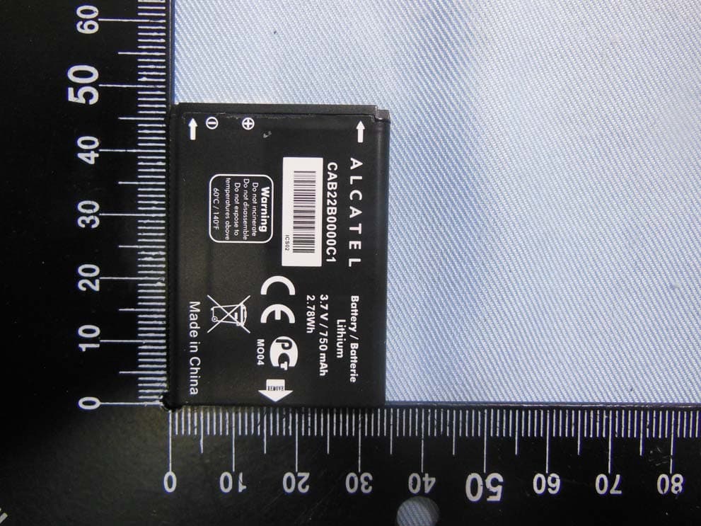
RAD556
Sep 08, 2015CDMA 1X BC0/BC1/BC10 mobile phone
Equipment Class
PCE - PCS Licensed Transmitter held to ear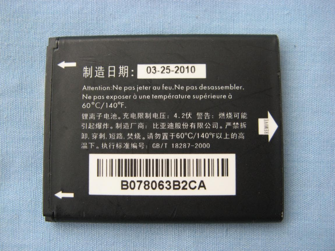
RAD552
Jun 20, 2015GSM Quadband / UMTS Triband mobile phone
Equipment Class
PCE - PCS Licensed Transmitter held to ear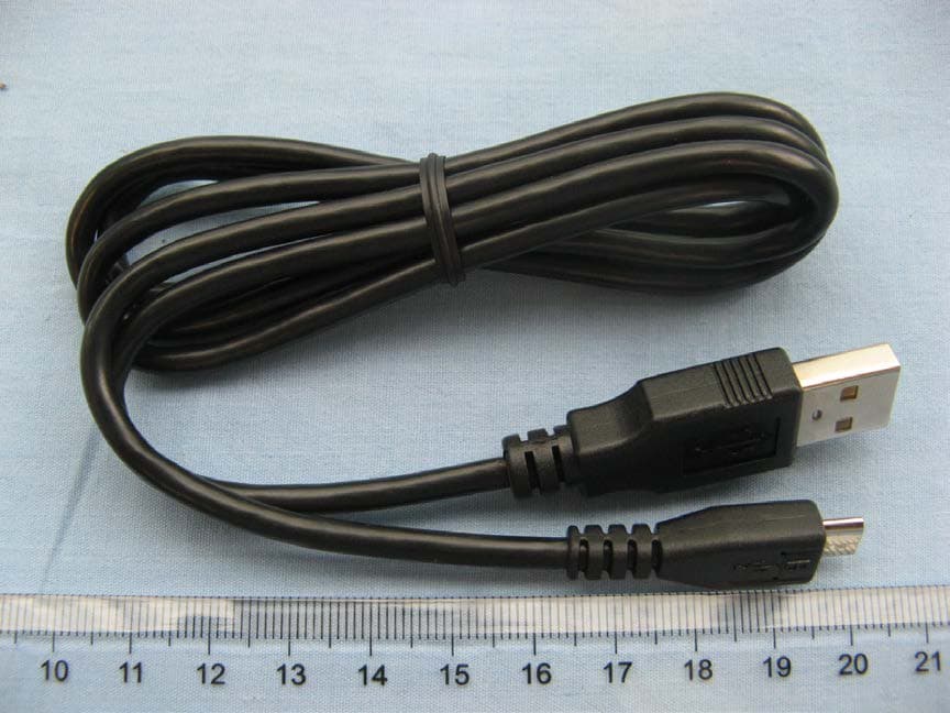
RAD550
Jun 06, 2015HSDPA/HSUPA/HSPA+/UMTS quad band /GSM quad band/LTE 4 band mobile phone
Equipment Class
DSS - Part 15 Spread Spectrum Transmitter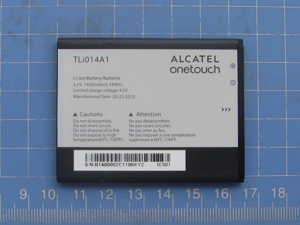
RAD549
May 13, 2015WCDMA tri band / GSM quad band Moblie phone with BT, Wi-Fi functionality.
Equipment Class
DSS - Part 15 Spread Spectrum Transmitter