RAD528HSDPA/HSUPA/HSPA+/CDMA dual band /LTE 1 band mobile phone
TCT Mobile LimitedApplication Details
- Equipment Class
- DTS - Digital Transmission System
- Date of Grant
- Feb 04, 2015
- Application Purpose
- Original Equipment
- Date of Application
- Feb 02, 2015
- Equipment Note
- HSDPA/HSUPA/HSPA+/CDMA dual band /LTE 1 band mobile phone
- Frequency Range
- 2402.00000000 - 2480.00000000
- Company
- TCT Mobile Limited
- Country
- China
Documents & Files
Document Text
Text extracted from the exhibit documents filed with the FCC. Open a document above to read the original.
Users Manual
English - CJB619601AAA Quick Start Guide BC A846L Thank you for choosing Alcatel ONETOUCH. This booklet helps you get started with your new Alcatel ONETOUCH Pop ICON LTETM 2. Important: Your phone has an embedded battery with a removable back cover and NON removable battery. Unauthorized personnel are strictly prohibited from disassembling the phone. Restart your phone by pressing and holding the Power key for more than 10 seconds until the startup screen appears. In case this does not start your phone, please press and hold the power key and volume up key together until the startup screen appears. From the following menus, short press the power key to select the language and then the “factory reset” option. Note: This operation will erase personal settings and saved data. For more information about how to use your Pop ICON LTETM 2, please go to www.alcatelonetouch.com for the complete user manual. 1 1 Your mobile device ............................ 1.1 Phone Overview Micro-USB Charging Port Front camera LED indicator Headset port Power key Home key Touchscreen Display Back key Menu key Volume key Table of contents 1 Your mobile device .............................................................................................................1 2 Text input...........................................................................................................................13 3 Phone call..........................................................................................................................15 4 People ................................................................................................................................16 5 Messaging .........................................................................................................................17 6 Email ..................................................................................................................................19 7 Getting connected .............................................................................................................20 8 Find my location using GPS satellites .............................................................................21 9 Data backup ......................................................................................................................22 10 Factory data reset ............................................................................................................23 11 Applications & Internal storage .......................................................................................23 12 Making the most of your phone .......................................................................................24 Safety and use .............................................................................................................................25 www.sar-tick.com This product meets applicable national SAR limits of 1.6 W/kg. The specific maximum SAR values can be found on page 34 of this user guide. When carrying the product or using it while worn on your body, either use an approved accessory such as a holster or otherwise maintain a distance of 1.0 cm from the body to ensure compliance with RF exposure requirements. Note that the product may be transmitting even if you are not making a phone call. PROTECT YOUR HEARING To prevent possible hearing damage, do not listen at high volume levels for long periods. Exercise caution when holding your device near your ear while the loudspeaker is in use. 23 Camera Camera Flash/ Flashlight Back key • Touch to go back to the previous screen, or to close a dialog box, options menu, the notification panel, etc. Home key • From any application or screen, touch to return to the Home screen. • Touch and hold to enter Google search. Menu key • Touch to access settings options. • Touch and hold to open a list of thumbnail images of apps you've worked with recently. These keys are visible when the screen lights up. Power key • Press: Lock the screen/Light up the screen. • Press and hold: Show the pop-up menu to select from Power off/Reboot/Airplane mode etc. • Press the Power key for more than 10 seconds to restart. • Press the Power key and Volume up key to reset if the phone is off. • Press the Power key and Volume down key to capture a screenshot. Volume Keys • In call mode, adjusts the earpiece or headset volume. • In Music/Video/Streaming mode, adjusts the media volume. • In general mode, adjusts the ringtone volume. • Mutes the ringtone of an incoming call. 1.2 Getting started 1.2.1 Set-up Removing and installing the back cover 45 Inserting or removing the SIM card You must insert your SIM card to make phone calls. You do not need to power off your phone before inserting or removing the SIM card due to hot swap functionality being supported. To install, place the SIM card with the chip facing downwards in to the housing, and then slide it into the slot. Make sure that it is correctly inserted. To remove the card, press inward and slide out. Your phone only supports micro-SIM cards. Do not attempt to insert other SIM cards such as mini or nano cards, or this may result in damage. Installing and removing the micro SD card Insert the micro SD card with the gold contact facing downwards into the slot. Slide it out to remove the micro SD card. To avoid data loss and SD card damage, please ensure that the SD card is unmounted (Settings\Storage\Unmount SD card) before removing the SD card. Charging the battery Connect the battery charger cable to your phone and main socket respectively, the LED indicator will light while charging. To reduce power consumption and energy waste when the battery is fully charged, disconnect your charger from the plug; switch off Wi-Fi, GPS, Bluetooth or background- running applications when not in use; reduce the backlight time, etc. 1.2.2 Power on your phone Hold down the Power key until the phone powers on. Set up your phone for the first time The first ti…
Text truncated - open the document above for the full version.
Cover Letter(s)
5F, C building, No. 232, Liang Jing Road ZhangJiang High-Tech Park, Pudong Area Shanghai, P.R. China. 201203 TEL: +86(0)21 61460666 FAX: +86(0)21 61460602 Date 2015-01-19 To: Federal Communications Commission, Authorization & Evaluation Division, 7345 Oakland Mills Road Columbia, MD 21046 And American Certification Body, Inc. 6731 Whittier Avenue Suite C110 McLean, VA 22101 To Whom It May Concern: CTTL-Terminals Test Lab of China Academy of Telecommunication Research of MIIT is authorized to act on our behalf, until otherwise notified, for applications to American Certification Body, Inc. (ACB). We certify that we are not subject to denial of federal benefits, which includes FCC benefits, pursuant to Section 5301 of the Anti-Drug Abuse Act of 1988, U.S.C. 862. Further, no party, as defined in 47 CFR1.2002 (b) to the application is subject to denial of federal benefits, that includes FCC benefits. Thank you. Regards, Zhizhou GONG Product Certification Manager TCT Mobile Limited
Cover Letter(s)
5F, E building, No. 232, Liang Jing Road ZhangJiang High-Tech Park, Pudong Area Shanghai, P.R. China. 201203 TEL: +86(0)21 61460666 FAX: +86(0)21 61460602 1/26/2015 Federal Communications Commission Office of Engineering and Technology Equipment Authorization Division 7345 Oakland Mills Road Columbia, Maryland 21046 Subject: Permanent Confidentiality request for FCC ID: RAD528 To Whom It May Concern, Pursuant to sections 0.457 and 0.459 of CFR 47, the applicant requests permanent confidential treatment of the following information accompanying this application: - Block Diagram - Schematics - Operational Description - BOM list/Tune-Up-Procedure The above materials contain trade secrets and proprietary information not customarily released to the public. The public disclosure of these matters might be harmful to the applicant and provide unjustified benefits to its competitors. Yours Sincerely, Zhizhou Gong Approval Team Leader TCT Mobile Limited
External Photos
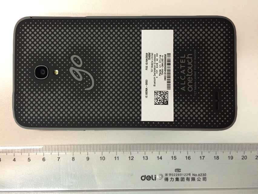
Exte ernal Photos
Internal Photos
Inter rnal Photos
RF Exposure Info
©Copyright. All rights reserved by CTTL. SAR TEST REPORT No. I14Z49085-SEM01 For TCT Mobile Limited HSDPA/HSUPA/HSPA+/CDMA dual band /LTE 1 band mobile phone Model Name: A846L With Hardware Version: PIO Software Version: 3JP6 FCC ID: RAD528 Issued Date: 2015-01-20 Note: The test results in this test report relate only to the devices specified in this report. T his report shall not be reproduced except in full without the written approval of CTTL. Test Laboratory: CTTL, Telecommunication Technology Labs, Academy of Telecommunication Research, MIIT No. 51 Shouxiang Science Building, Xueyuan Road, Haidian District, Beijing, P. R. China100191 Tel :+86(0)10-62304633-2512,Fax:+86(0)10-62304633-2504 Email: cttl_terminals@catr .cn, website:www.chinattl.com TESTING CNAS L0570 No. I14Z49085-SEM01 Page 2 of 118 ©Copyright. All rights reserved by CTTL. REPORT HISTORY Report Number Revision Issue Date Description I14Z49085-SEM01 Rev.0 2015-01-20 Initial creation of test report No. I14Z49085-SEM01 Page 3 of 118 ©Copyright. All rights reserved by CTTL. TABLE OF CONTENT 1 TEST LABORATORY .................................................................................................................... 5 1.1 TESTING LO C AT I O N ........................................................................................................................................ 5 1.2 TESTING ENVIRONMENT ................................................................................................................................. 5 1.3 PROJECT DATA ............................................................................................................................................... 5 1.4 SIGNATURE ..................................................................................................................................................... 5 2 STATEMENT OF COMPLIANCE .................................................................................................. 6 3 CLIENT INFORMATION ................................................................................................................ 7 3.1 APPLICANT INFORMATION .............................................................................................................................. 7 3.2 MANUFACTURER INFORMATION ..................................................................................................................... 7 4 EQUIPMENT UNDER TEST (EUT) AND ANCILLARY EQUIPMENT (AE) ................................. 8 4.1 ABOUT EUT ................................................................................................................................................... 8 4.2 INTERNAL IDENTIFICATION OF EUT USED DURING THE TEST .......................................................................... 8 4.3 INTERNAL IDENTIFICATION OF AE USED DURING THE TEST ............................................................................ 8 5 TEST METHODOLOGY ................................................................................................................ 9 5.1 APPLICABLE LIMIT REGULATIONS .................................................................................................................. 9 5.2 APPLICABLE MEASUREMENT STANDARDS ...................................................................................................... 9 6 SPECIFIC ABSORPTION RATE (SAR) ...................................................................................... 10 6.1 INTRODUCTION ............................................................................................................................................. 10 6.2 SAR DEFINITION .......................................................................................................................................... 10 7 TISSUE SIMULATING LIQUIDS ................................................................................................. 11 7.1 TARGETS FOR TISSUE SIMULATING LIQUID .................................................................................................... 11 7.2 DIELECTRIC PERFORMANCE ......................................................................................................................... 11 8 SYSTEM VERIFICATION ............................................................................................................ 16 8.1 SYSTEM SETUP ............................................................................................................................................. 16 8.2 SYSTEM VERIFICATION ................................................................................................................................. 17 9 MEASUREMENT PROCEDURES .............................................................................................. 18 9.1 TESTS TO BE PERFORMED ............................................................................................................................. 18 9.2 GENERAL MEASUREMENT PROCEDURE ........................................................................................................ 19 9.3 BLUETOOTH & WI-FI MEASUREMENT PROCEDURES FOR SAR .................................................................... 20 9.4 POWER DRIFT ............................................................................................................................................... 21 10 AREA SCAN BASED 1-G SAR ................................................................................................. 21 10.1 REQUIREMENT OF KDB .............................................................................................................................. 21 10.2 FAST SAR ALGORITHMS ............................................................................................................................ 21 11 CONDUCTED OUTPUT POWER .............................................................................................. 22 11.1 MANUFACTURING TOLERANCE ...…
Text truncated - open the document above for the full version.
RF Exposure Info
No. I14Z49085-SEM01 Page 68 of 118 ©Copyright. All rights reserved by CTTL. Picture C.7 Server for DASY 4 Picture C.8 Server for DASY 5 C.4.4 Device Holder for Phantom The SAR in the phantom is approximately inversely proportional to the square of the distance between the source and the liquid surface. For a source at 5mm distance, a positioning uncertainty of ±0.5mm would produce a SAR uncertainty of ±20%. Accurate device positioning is therefore crucial for accurate and repeatable measurements. The positions in which the devices must be measured are defined by the standards. The DASY device holder is designed to cope with the different positions given in the standard. It has two scales for device rotation (with respect to the body axis) and device inclination (with respect to the line between the ear reference points). The rotation centers for both scales is the ear reference point (ERP). Thus the device needs no repositioning when changing the angles. The DASY device holder is constructed of low-loss POM material having the following dielectric parameters: relative permittivity ε =3 and loss tangent δ =0.02. The amount of dielectric material has been reduced in the closest vicinity of the device, since measurements have suggested that the influence of the clamp on the test results could thus be lowered. <Laptop Extension Kit> The extension is lightweight and made of POM, acrylic glass and foam. It fits easily on the upper part of the Mounting Device in place of the phone positioner. The extension is fully compatible with the Twin-SAM and ELI phantoms. Picture C.9-1: Device Holder Picture C.9-2: Laptop Extension Kit C.4.5 Phantom The SAM Twin Phantom V4.0 is constructed of a fiberglass shell integrated in a table. The shape of the shell is based on data from an anatomical study designed to Represent the 90 th percentile of the population. The phantom enables the dissymmetric evaluation No. I14Z49085-SEM01 Page 69 of 118 ©Copyright. All rights reserved by CTTL. of SAR for both left and right handed handset usage, as well as body-worn usage using the flat phantom region. Reference markings on the Phantom allow the complete setup of all predefined phantom positions and measurement grids by manually teaching three points in the robot. The shell phantom has a 2mm shell thickness (except the ear region where shell thickness increases to 6 mm). Shell Thickness: 2 ± 0. 2 mm Filling Volume: Approx. 25 liters Dimensions: 810 x l000 x 500 mm (H x L x W) Avai lable : Special Picture C.10: SAM Twin Phantom No. I14Z49085-SEM01 Page 70 of 118 ©Copyright. All rights reserved by CTTL. ANNEX D Position of the wireless device in relation to the phantom D.1 General considerations This standard specifies two handset test positions against the head phantom – the “cheek” position and the “tilt” position. t w Width of the handset at the level of the acoustic b w Width of the bottom of the handset A Midpoint of the width t w of the handset at the level of the acoustic output B Midpoint of the width b w of the bottom of the handset Picture D.1-a Typical “fixed” case handset Picture D.1-b Typical “clam-shell” case handset Picture D.2 Cheek position of the wireless device on the left side of SAM No. I14Z49085-SEM01 Page 71 of 118 ©Copyright. All rights reserved by CTTL. Picture D.3 Tilt position of the wireless device on the left side of SAM D.2 Body-worn device A typical example of a body-worn device is a mobile phone, wireless enabled PDA or other battery operated wireless device with the ability to transmit while mounted on a person’s body using a carry accessory approved by the wireless device manufacturer. Picture D.4 Test positions for body-worn devices D.3 Desktop device A typical example of a desktop device is a wireless enabled desktop computer placed on a table or desk when used. The DUT shall be positioned at the distance and in the orientation to the phantom that corresponds to the intended use as specified by the manufacturer in the user instructions. For devices that employ an external antenna with variable positions, tests shall be performed for all antenna positions specified. Picture 8.5 show positions for desktop device SAR tests. If the intended use is not specified, the device shall be tested directly against the flat phantom. No. I14Z49085-SEM01 Page 72 of 118 ©Copyright. All rights reserved by CTTL. Picture D.5 Test positions for desktop devices D.4 DUT Setup Photos Picture D.6 No. I14Z49085-SEM01 Page 73 of 118 ©Copyright. All rights reserved by CTTL. ANNEX E Equivalent Media Recipes The liquid used for the frequency range of 800-3000 MHz consisted of water, sugar, salt, preventol, glyc ol monobutyl and Cellulose. The liquid has been previously proven to be suited for worst-case. The Table E.1 shows the detail solution. It’s satisfying the latest tissue dielectric parameters requirements proposed by the IEEE 1528 and IEC 62209. Table E.1: Composition of the Tissue Equivalent Matter Frequency (MHz) 835 Head 835 Body 1900 Head 1900 Body 2450 Head 2450 Body 5800 Head 5800 Body Ingredients (% by weight) Water 41.45 52.5 55.242 69.91 58.79 72.60 65.53 65.53 Sugar 56.0 45.0 \ \ \ \ \ \ Sal t 1.45 1.4 0.306 0.13 0.06 0.18 \ \ Preventol 0.1 0.1 \ \ \ \ \ \ Cellulose 1.0 1.0 \ \ \ \ \ \ Glycol Monobutyl \ \ 44.452 29.96 41.15 27.22 \ \ Diethylenglycol monohexylether \ \ \ \ \ \ 17.24 17.24 Triton X-100 \ \ \ \ \ \ 17.24 17.24 Dielectric Parameters Target Value ε=41.5 σ=0.90 ε=55.2 σ=0.97 ε=40.0 σ=1.40 ε=53.3 σ=1.52 ε=39.2 σ=1.80 ε=52.7 σ=1.95 ε=35.3 σ=5.27 ε=48.2 σ=6.00 No. I14Z49085-SEM01 Page 74 of 118 ©Copyright. All rights reserved by CTTL. ANNEX F System Validation The SAR system must be validated against its performance specifications before it is deployed. When SAR probes, system components or software are changed, upgraded or recalibrated, these must be validated with the SAR system(s) that operates with such components. Table F.1: System Validation Probe SN. Liquid name Validation date Freq…
Text truncated - open the document above for the full version.
Test Report
SDPA/HS est results in duced except Laboratory: , Telecommu n 2, HuayuanNo 86(0)10-62304 :cttl_terminals N SUPA/HSP this test rep in full without nication Techn orth Road, Haid 4633-2512,Fax [email protected], we FCC TES No. I14 I14 PA+/CDM MOD FC Hardw Softw Issued ort relate onl the written a p ology Labs, A dian District, B x:+86(0)10-62 bsite:www.chi C PAR STRE Z4908 for 4Z49085- MA dual DEL NAM with CC ID: R ware Ver ware Vers d Date: 2 y to the devi pproval of CTT Academy of Te Beijing, P. R. C 2304633-2504 inattl.com C RT 15 EPOR 85-SR -SRD01 band /L T ME: A846 h RAD528 rsion: PI sion: 3JP 2015-01- ces specified TL. elecommunica China 100191 4 TESTING CNAS L0570 ©Copyright. A 5C RT RD01 TE 1 band L O P6 15 in this repor tion Research . All rights reser d mobile rt. This report h, MIIT rved by CTTL. e phone t shall not be . e REP Repo I14Z4 PORT H ort Number 49085-SRD HISTORY r 01 Y Revision Rev.0 D 1 Description st edition No. I1 ©Copyright. A 14Z49085 Page2 All rights reser Issue Date 2015-01-15 5-SRD01 2 of 95 rved by CTTL. e 5 . CO 1. T 1.1. 1.2. 1.3. 1.4. 2. C 2.1. 2.2. 3. E 3.1. 3.2. 3.3. 3.4. 3.5. 4. R 4.1. 4.2. 5. T 5.1. 5.2. 5.3. 6. T ANN A.1. A.2. A. 2 A.2 A.3. A.4. A.5. A.6. T NTENTS TEST LABO TESTING TESTING PROJECT SIGNATU CLIENTINF APPLIC A MANUFA EQUIPMEN ABOUT E INTERNA INTERNA GENERA INTERPR REFERENC DOCUME REFEREN TEST RESU SUMMAR STATEME TEST CO TEST FACIL EX A: DETA MEASUREM MAXIMUM 2.1. PEAK OU 2.2. AVERAG PEAK POW DTS 6-DB S BAND EDG TRANSMIT S ORATORY .. GLOCATION GENVIRONM T DATA ...... URE ............ ORMATIO N ANT INFORM ACTURER IN NT UNDERT EUT ............ AL IDENTIFI AL IDENTIFI AL DESCRIP RETATION O CE DOCUME ENTS SUPP NCE DOCU ULTS .......... RY OF TEST ENTS ......... ONDITIONS LITIES UTIL AILED TEST MENT MET OUTPUT P UTPUT POWE E OUTPUT P WER SPECT SIGNAL BA GES COMPL TTER SPUR .................. . N .................. MENT .......... ................... ................... N .................. MATION...... NFORMATIO EST (EUT) .................. . ICATION OF ICATION OF PTION ......... OF THE TES ENTS ......... PLIED BY AP MENTS FO ................... T RESULTS .................. . ................... LIZED ......... T RESULTS HOD ........... OWER ....... ER-CONDUCT OWER-COND TRAL DENS ANDWIDTH . LIANCE ...... IOUS EMIS ................... ................... ................... ................... ................... ................... ................... ON .............. AND ANCIL ................... F EUT ........ F AE ........... ................... ST ENVIRON ................... PPLICANT . OR TESTING ................... .................. ................... ................... ................... S ................. ................... ................... TED .............. DUCTED ........ SITY ............ ................... ................... SION ......... ................... ................... ................... ................... ................... ................... ................... ................... LLARY EQU ................... ................... ................... ................... NMENT ..... ................... ................... G ................. ................... ................... ................... ................... ................... ................... ................... ................... ................... ................... ................... ................... ................... ................... No. I1 ©Copyright. A ................... ................... ................... ................... ................... ................... ................... ................... UIPMENT (A ................... ................... ................... ................... ................... ................... ................... ................... ................... ................... ................... ................... ................... ................... ................... ................... ................... ................... ................... ................... ................... ................... 14Z49085 Page3 All rights reser ................... ................... ................... ................... ................... ................... ................... ................... AE) ............. ................... ................... ................... ................... ................... ................... ................... ................... ................... ................... ................... ................... ................... ................... ................... ................... ................... ................... ................... ................... ................... ................... 5-SRD01 3 of 95 rved by CTTL. ................. 5 ................. 5 ................. 5 ................. 5 ................. 5 ................. 6 ................. 6 ................. 6 ................. 7 ................. 7 ................. 7 ................. 7 ................. 8 ................. 8 ................. 8 ................. 8 ................. 8 ................. 9 ................. 9 ................. 9 ................. 9 ............... 10 ............... 11 ............... 11 ............... 12 ............... 12 ............... 13 ............... 14 ............... 20 ............... 26 ............... 30 . 5 5 5 5 5 6 6 6 7 7 7 7 8 8 8 8 8 9 9 9 9 0 2 2 3 4 0 6 0 A.6 A.6 A.7. A ANN 6.1 TRANSMI 6.2 TRANSMI AC POWER EX B: ACC TTER SPURIO TTER SPURIO R-LINE CON REDITATIO OUS EMISSIO OUS EMISSIO NDUCTED E ON CERTIFIC ON – CONDUC ON - RADIATE EMISSION .. CATE ......... CTED ........... ED ............... ................... ................... No. I1 ©Copyright. A ................... ................... ................... ................... 14Z49085 Page4 All rights reser ................... ................... ................... ................... 5-SRD01 4 of 95 rved by CTTL. ............... 30 ............... 70 ....…
Text truncated - open the document above for the full version.
Test Report
F Fig.A.6.1.4 Fig.A.6.1.44 3 Transm 4 Transmi mitter Spurio tter Spurio ous Emissi us Emissio on - Condu GHz) on - Conduc GHz) No. I1 ©Copyright. A ucted (802.1 cted (802.11 14Z49085 Page55 All rights reser 11g, Ch11, 1 1g, Ch11, 2. 5-SRD01 5 of 95 rved by CTTL. 1 GHz-2.5 .5 GHz-7.5 . F Fig.A.6.1.45 Fig.A.6.1.46 5 Transmi 6 Transm itter Spurio itter Spurio ous Emissio ous Emissio on - Conduc GHz) on - Condu GHz) No. I1 ©Copyright. A cted (802.11 cted (802.1 14Z49085 Page56 All rights reser 1g, Ch11, 7 1g, Ch11, 1 5-SRD01 6 of 95 rved by CTTL. .5 GHz-10 0 GHz-15 . Fig.A.6.1.47 Fig.A.6.1.48 7 Transm 8 Transm itter Spurio itter Spurio ous Emissio ous Emissio on - Condu GHz) on - Condu GHz) No. I1 ©Copyright. A cted (802.1 cted (802.1 14Z49085 Page57 All rights reser 1g, Ch11, 1 1g, Ch11, 2 5-SRD01 7 of 95 rved by CTTL. 5 GHz-20 20 GHz-26 . F Fi Fig.A.6.1.49 g.A.6.1.50 9 Transmi Transmit t tter Spurio ter Spuriou us Emissio Fr s Emission on - Conduc requency) n - Conduct GHz) No. I1 ©Copyright. A cted (802.11 ed (802.11n 14Z49085 Page58 All rights reser 1n-HT20, Ch n-HT20, Ch1 5-SRD01 8 of 95 rved by CTTL. h1, Center 1, 30 MHz-1 . Fig.A.6.1 Fig.A.6.1. 5 .51 Trans 52 Transm smitter Spu mitter Spur rious Emis G H ious Emiss GH sion - Cond Hz-2.5 GHz) sion - Cond Hz-7.5 GHz) No. I1 ©Copyright. A ducted (802 ucted (802. 14Z49085 Page59 All rights reser 2.11n-HT20, .11n-HT20, 5-SRD01 9 of 95 rved by CTTL. , Ch1, 1 Ch1, 2.5 . Fig.A.6.1.5 Fig.A.6.1. 53 Transm 54 Transm mitter Spur mitter Spur ious Emiss GH rious Emiss GH sion - Cond Hz-10 GHz) sion - Cond Hz-15 GHz) No. I1 ©Copyright. A ucted (802. ucted (802 . 14Z49085 Page60 All rights reser .11n-HT20, .11n-HT20, 5-SRD01 0 of 95 rved by CTTL. Ch1, 7.5 Ch1, 10 . Fig.A.6.1. Fig.A.6.1. 55 Transm 56 Transm mitter Spur mitter Spur rious Emiss GH rious Emiss GH sion - Cond Hz-20 GHz) sion - Cond Hz-26 GHz) No. I1 ©Copyright. A ucted (802. ucted (802. 14Z49085 Page61 All rights reser .11n-HT20, .11n-HT20, 5-SRD01 1 of 95 rved by CTTL. Ch1, 15 Ch1, 20 . F Fi Fig.A.6.1.57 g.A.6.1.58 7 Transmi Transmit t tter Spurio ter Spuriou us Emissio Fr s Emission on - Conduc requency) n - Conduct GHz) No. I1 ©Copyright. A cted (802.11 ed (802.11n 14Z49085 Page62 All rights reser 1n-HT20, Ch n-HT20, Ch6 5-SRD01 2 of 95 rved by CTTL. h6, Center 6, 30 MHz-1 . Fig.A.6.1 Fig.A.6.1. 6 .59 Trans 60 Transm smitter Spu mitter Spur rious Emis G H ious Emiss GH sion - Cond Hz-2.5 GHz) sion - Cond Hz-7.5 GHz) No. I1 ©Copyright. A ducted (802 ucted (802. 14Z49085 Page63 All rights reser 2.11n-HT20, .11n-HT20, 5-SRD01 3 of 95 rved by CTTL. , Ch6, 1 Ch6, 2.5 . Fig.A.6.1.6 Fig.A.6.1. 61 Transm 62 Transm mitter Spur mitter Spur ious Emiss GH rious Emiss GH sion - Cond Hz-10 GHz) sion - Cond Hz-15 GHz) No. I1 ©Copyright. A ucted (802. ucted (802 . 14Z49085 Page64 All rights reser .11n-HT20, .11n-HT20, 5-SRD01 4 of 95 rved by CTTL. Ch6, 7.5 Ch6, 10 . Fig.A.6.1. Fig.A.6.1. 63 Transm 64 Transm mitter Spur mitter Spur rious Emiss GH rious Emiss GH sion - Cond Hz-20 GHz) sion - Cond Hz-26 GHz) No. I1 ©Copyright. A ucted (802. ucted (802. 14Z49085 Page65 All rights reser .11n-HT20, .11n-HT20, 5-SRD01 5 of 95 rved by CTTL. Ch6, 15 Ch6, 20 . F ig.A.6.1.65 Fig.A.6.1. 6 Transmit 66 Transm tter Spuriou mitter Spuri us Emission Fr ious Emiss M n - Conduct requency) ion - Cond u Hz-1 GHz) No. I1 ©Copyright. A ted (802.11n ucted (802.1 14Z49085 Page66 All rights reser n-HT20, Ch 11n-HT20, C 5-SRD01 6 of 95 rved by CTTL. h11, Center Ch11, 30 . Fig.A.6.1. Fig.A.6.1. 6 67 Transm 68 Transm mitter Spur mitter Spuri rious Emiss GH ous Emissi GH sion - Cond Hz-2.5 GHz) ion - Condu Hz-7.5 GHz) No. I1 ©Copyright. A ducted (802. ucted (802.1 14Z49085 Page67 All rights reser .11n-HT20, 11n-HT20, C 5-SRD01 7 of 95 rved by CTTL. Ch11, 1 Ch11, 2.5 . Fig.A.6.1.6 Fig.A.6.1.7 69 Transm 70 Transm mitter Spuri mitter Spuri ous Emissi GH ious Emiss G H ion - Condu Hz-10 GHz) ion - Cond u Hz-15 GHz) No. I1 ©Copyright. A ucted (802.1 ucted (802.1 14Z49085 Page68 All rights res…
Text truncated - open the document above for the full version.
Contact Information
Applicant
Zhizhou Gong
Technical Contact
CTTL-Terminals Test Lab of China Academy of TelecoXue Zhen
[email protected]+86-62304633
No. 52, Huayuan Bei Road, Haidian District, · Beijing · China
Test Firm
Telecommunication Technology Labs,zhen xue
[email protected]861062304633
Technical Specifications
| # | Rule Parts | Frequency Range | Power Output |
|---|---|---|---|
| 2 | 15C | 2.40 GHz - 2.48 GHz | 2.10 mW |
Other Applications from TCT Mobile Limited
RAD558
Nov 15, 2015HSUPA/HSDPA/UMTS tribands / GSM quadbands/LTE 6-band mobile phone
Equipment Class
JBP - Part 15 Class B Computing Device Peripheral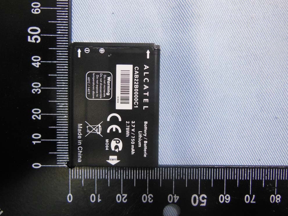
RAD556
Sep 08, 2015CDMA 1X BC0/BC1/BC10 mobile phone
Equipment Class
PCE - PCS Licensed Transmitter held to ear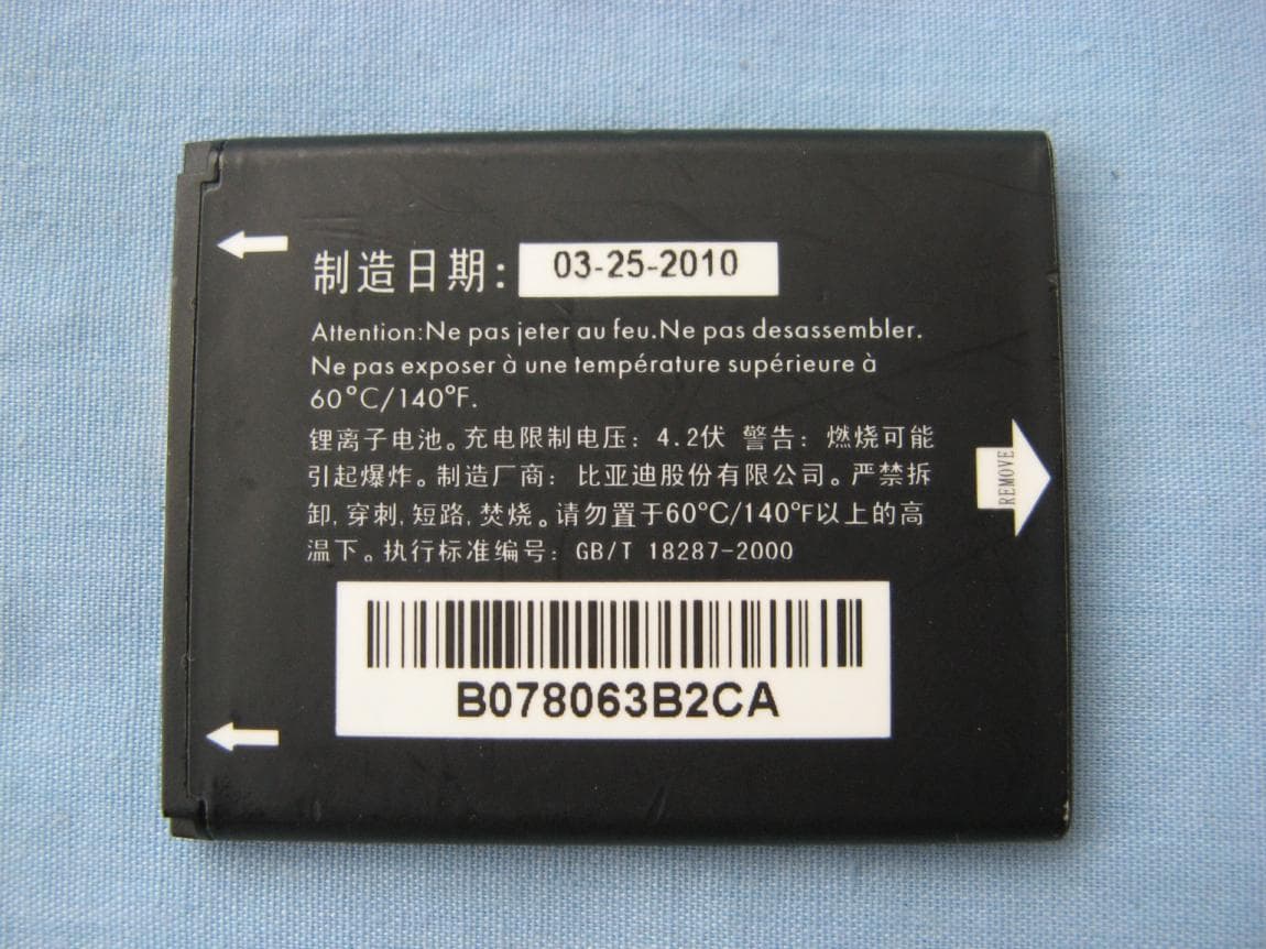
RAD552
Jun 20, 2015GSM Quadband / UMTS Triband mobile phone
Equipment Class
PCE - PCS Licensed Transmitter held to ear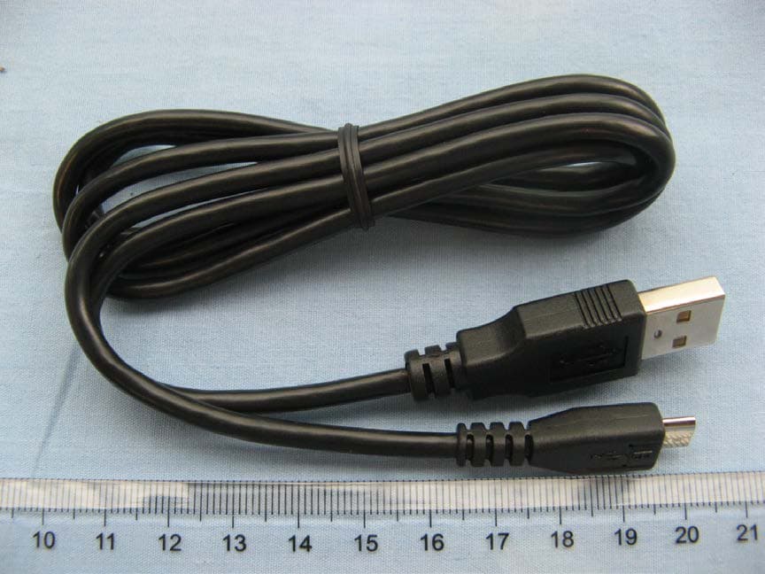
RAD550
Jun 06, 2015HSDPA/HSUPA/HSPA+/UMTS quad band /GSM quad band/LTE 4 band mobile phone
Equipment Class
DSS - Part 15 Spread Spectrum Transmitter
RAD549
May 13, 2015WCDMA tri band / GSM quad band Moblie phone with BT, Wi-Fi functionality.
Equipment Class
DSS - Part 15 Spread Spectrum Transmitter