RAFXBT-DG2GX-Micro Bluetooth USB Dongle
X-Micro Technology Corp.,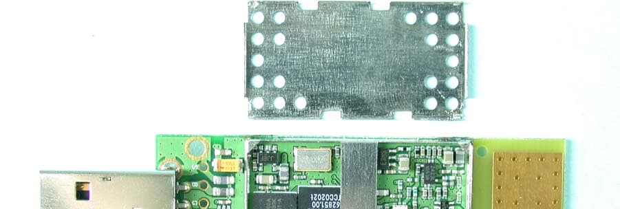
Click to zoom
Application Details
- Equipment Class
- DSS - Part 15 Spread Spectrum Transmitter
- Date of Grant
- Nov 12, 2003
- Application Purpose
- Original Equipment
- Date of Application
- Nov 12, 2003
- Equipment Note
- X-Micro Bluetooth USB Dongle
- Frequency Range
- 2402.00000000 - 2480.00000000
- Company
- X-Micro Technology Corp.,
- Country
- Taiwan
Documents & Files
Document Text
Text extracted from the exhibit documents filed with the FCC. Open a document above to read the original.
Cover Letter(s)
American Telecommunications Certification Body Inc. 6731 Whittier Ave, McLean, VA 22101 November 6, 2003 RE: X-micro Technology Corp. FCC ID: RAFXBT-DG2G I have a few comments on the above referenced Application. 1) The FRN Number provided (0009222233) appears not to be valid from checking on the FCC website. Please provide a correct FRN number for X-Micro Technology Corp. Note that a grant can not be issued without this. 2) Certain characters of the FCC ID on the label are not easily readable. Please provide a higher resolution label that is clear. 3) FYI. The RF exposure exhibit mentions 2.5 cm distance. This distance is not necessarily correct for the type of device since touch conditions can occur. However, due to the power output and gain of the antenna, an RF exposure exhibit is not necessary. Therefore the exhibit provided will be ignored. 4) The 20 cm distance given in the users manual (page 2 of 62) is not applicable to this type of device. Touch conditions can occur. However due to the EIRP of this device, it is not necessary to cite a distance in the users manual. Please remove this sentence from the users manual. 5) The users manual (page 61 of 62) states that this device is a Class 1 Bluetooth device. Note that a Class 1 device is 100 mW (20 dBm). Additionally, the test report states the device is a Class 1. Please explain. Note that Class 1 = 20 dBm, Class 2 = 4 dBm Class 3 = 0 dBm. Timothy R. Johnson Examining Engineer mailto: [email protected] The items indicated above must be submitted before processing can continue on the above referenced application. Failure to provide the requested information may result in application termination. Correspondence should be considered part of the permanent submission and may be viewed from the Internet after a Grant of Equipment Authorization is issued. Please do not respond to this correspondence using the email reply button. In order for your response to be processed expeditiously, you must submit your documents through the AmericanTCB.com website. Also, please note that partial responses increase processing time and should not be submitted. Any questions about the content of this correspondence should be directed to the sender.
ID Label/Location Info
Label Location
Internal Photos
Page 3 Page 4 Page 5
Operational Description
BLUETOOTH APPROVALS The following exhibit indicates the FCC Spread Spectrum requirements in Section 15.247 for devices meeting the Bluetooth Specifications in the 2.4 GHz band as of February 2001 operating in the USA. The purpose of this exhibit is to help expedite the approval process for Bluetooth devices. This exhibit provides items that vary for each device and also provides a list of items that are common to Bluetooth devices that explains the remaining requirements. The list of common items can be submitted for each application for equipment authorization. This exhibit only specifies requirements in Section 15.247, requirements in other rule Sections for intentional radiators such as in Section 15.203 or 15.207 must be also be addressed. For each individual device, the following items, 1-7 will vary from one device to another and must be submitted. 1) The occupied bandwidth in Section 15.247(a)(1)(ii). 2) Conducted output power specified in Section 15.247(b)(1). 3) EIRP limit in Section 15.247(b)(3). 4) RF safety requirement in Section 15.247(b)(4) 5) Spurious emission limits in Section 15.247©. 6) Processing gain and requirements for Hybrids in Section 15.247(f) in the acquisition mode. 7) Power spectral density requirement in Section 15.247(f) in the acquisition mode. For all devices, the following items, 1-12, are common to all Bluetooth devices and will not vary from one device to another. This list can be copied into the filing. 1 Output power and channel separation of a Bluetooth device in the different operating modes: The different operating modes (data-mode, acquisition-mode) of a Bluetooth device don’t influence the output power and the channel spacing. There is only one transmitter which is driven by identical input parameters concerning these two parameters. Only a different hopping sequence will be used. For this reason, the RF parameters in one op-mode is sufficient. 2 Frequency range of a Bluetooth device: The maximum frequency of the device is: 2402 – 2480 MHz. This is according the Bluetooth Core Specification V 1.0B (+ critical errata) for devices which will be operated in the USA. Other frequency ranges ( e.g. for Spain, France, Japan) which are allowed according the Core Specification must not be supported by the device. 3 Co-ordination of the hopping sequence in data mode to avoid simultaneous occupancy by multiple transmitters: Bluetooth units which want to communicate with other units must be organized in a structure called piconet. This piconet consist of max. 8 Bluetooth units. One unit is the master the other seven are the slaves. The master co-ordinates frequency occupation in this piconet for all units. As the master hop sequence is derived from it’s BD address which is unique for every Bluetooth device, additional masters intending to establish new piconets will always use different hop sequences. 4 Example of a hopping sequence in data mode: Example of a 79 hopping sequence in data mode: 40, 21, 44, 23, 42, 53, 46, 55, 48, 33, 52, 35, 50, 65, 54, 67, 56, 37, 60, 39, 58, 69, 62, 71, 64, 25, 68, 27, 66, 57, 70, 59, 72, 29, 76, 31, 74, 61, 78, 63, 01, 41, 05, 43, 03, 73, 07, 75, 09, 45, 13, 47, 11, 77, 15, 00, 64, 49, 66, 53, 68, 02, 70, 06, 01, 51, 03, 55, 05, 04 5 Equally average use of frequencies in data mode and short transmissions: The generation of the hopping sequence in connection mode depends essentially on two input values: 1. LAP/UAP of the master of the connection 2. Internal master clock The LAP (lower address part) are the 24 LSB’s of the 48 BD_ADDRESS. The BD_ADDRESS is an unambiguous number of every Bluetooth unit. The UAP (upper address part) are the 24 MSB’s of the 48 BD_ADDRESS. The internal clock of a Bluetooth unit is derived from a free running clock which is never adjusted and is never turned off. For synchronization with other units, only the offsets are used. It has no relation to the time of the day. Its resolution is at least half the RX/TX slot length of 312.5 μs. The clock has a cycle of about one day (23h30). In most case it is implemented as 28 bit counter. For the deriving of the hopping sequence the entire LAP (24 bits), 4 LSB’s (4 bits) (Input 1) and the 27 MSB’s of the clock (Input 2) are used. With this input values different mathematical procedures (permutations, additions, XOR-operations) are performed to generate the sequence. This will be done at the beginning of every new transmission. Regarding short transmissions, the Bluetooth system has the following behavior: The first connection between the two devices is established, a hopping sequence is generated. For transmitting the wanted data, the complete hopping sequence is not used and the connection ends. The second connection will be established. A new hopping sequence is generated. Due to the fact that the Bluetooth clock has a different value, because the period between the two transmission is longer (and it cannot be shorter) than the minimum resolution of the clock (312.5 μs). The hopping sequence will always differ from the first one. 6 Receiver input bandwidth, synchronization and repeated single or multiple packets: The input bandwidth of the receiver is 1 MHz. In every connection, one Bluetooth device is the master and the other one is the slave. The master determines the hopping sequence (see chapter 5). The slave follows this sequence. Both devices shift between RX and TX time slot according to the clock of the master. Additionally the type of connection (e.g. single or multi-slot packet) is set up at the beginning of the connection. The master adapts its hopping frequency and its TX/RX timing is according to the packet type of the connection. Also, the slave of the connection uses these settings. Repeating of a packet has no influence on the hopping sequence. The hopping sequence generated by the master of the connection will be followed in any case. That means, a repeated packet will not be send on the same frequency, it is send on the next frequency …
Text truncated - open the document above for the full version.
Operational Description
FCC ID: RAFXBT-DG2G ADT No.920213R06C Operational Description The transmitter of the EUT is powered by host equipment from USB port. The antenna is Printed Patch Antenna, and there is no antenna connector. This device is a Frequency Hopping device with 79 hopping frequencies. The other instruction, please have a look at the users manual.
RF Exposure Info
FCC ID: RAFXBT-DG2G ADT No.: 920213R06C FCC TEST REPORT REPORT NO.: RF920213R06C MODEL NO.: XBT-DG2G ACCORDING: FCC Guidelines for Human Exposure IEEE C95.1 APPLICANT: X-Micro Technology Corp ADDRESS: 13F-4, No.738, Chung Cheng Road, Chung Ho City, Taipei Hsien, Taiwan ISSUED BY: Advance Data Technology Corporation LAB LOCATION: 47 14th Lin, Chiapau Tsun, Linko, Taipei, Taiwan, R.O.C. 0528 ILAC MRA Lab Code: 200102-0 FCC ID: RAFXBT-DG2G ADT No.: 920213R06C RF Exposure Measurement (Portable Device) 1. Introduction 2.4GHz frequency band is regarded specially as a dangerous band for its heating harmfulness to the human body. That’s why microwave oven is operating in this frequency band. The manufacturer whose product is working in this frequency band is obligatory to prove the harmfulness of his product. In this document, we try to prove the safety of radiation harmfulness to the human body for our product. The limit for Maximum Permissible Exposure (MPE) specified in FCC 1.1310 is followed. The Gain of the antenna used in this product is measured in a Fully Anechoic Chamber (FAC), and the maximum total power input to the antenna is measured. Through the Friis transmission formula and the maximum gain of the antenna, we can calculate the distance, away from the product, where the limit of MPE is reached. 2. RF Exposure Limit According to FCC 1.1310: The criteria listed in the following table shall be used to evaluate the environmental impact of human exposure to radio-frequency (RF) radiation as specified in 1.1307(b). FCC ID: RAFXBT-DG2G ADT No.: 920213R06C LIMITS FOR MAXIMUM PERMISSIBLE EXPOSURE (MPE) Frequency Range (MHz) Electric Field Strength (V/m) Magnetic Field Strength (A/m) Power Density (mW/cm 2 ) Average Time (minutes) (A)Limits For Occupational / Control Exposures 30-30061.40.1631.06 300-1500......F/3006 1500-100,000......56 (B)Limits For General Population / Uncontrolled Exposure 30-30027.50.0730.230 300-1500......F/150030 1500-100,000......1.030 F = Frequency in MHz 3. Friis Formula Friis transmission formula : Pd = (Pout*G) / (4*pi*r 2 ) where Pd = power density in mW/cm 2 Pout = output power to antenna in mW G = gain of antenna in linear scale Pi = 3.1416 R = distance between observation point and center of the radiator in cm Pd is the limit of MPE, 1 mW/cm 2 . If we know the maximum Gain of the antenna and the total power input to the antenna, through the calculation, we will know the distance r where the MPE limit is reached. Ref. : David K. Cheng, Field and Wave Electromagnetics, Second Edition, Page 640, Eq. (11-133). 4. EUT Operating condition The software provided by Manufacturer enabled the EUT to transmit and receive data at lowest, middle and highest channel individually. FCC ID: RAFXBT-DG2G ADT No.: 920213R06C 5. Test Results 5.1 Antenna Gain The maximum Gain measured in Fully Anechoic Chamber is 3dBi or 2.0 (numeric). 5.2 Output Power Into Antenna & RF Exposure Distance : CHANNEL CHANNEL FREQUENCY (MHz) OUTPUT POWER TO ANTENNA (mW) MINIMUM ALLOWABLE DISTANCE ( r ) FROM SKIN (Centi-Meter) 024029.9081.254 3924419.8171.248 7824809.7491.244 The minimum allowable distance is very close to the enclosure of the antenna. So, the user has no need to worry about the harmfulness of radiation.
Test Report
FCC ID: RAFXBT-DG2G Report No.: RF920213R06C1Issued: November 04, 2003 Reference No.: RF920213R06 FCC TEST REPORT REPORT NO.: RF920213R06C MODEL NO.: XBT-DG2G RECEIVED: NA TESTED: Feb. 19 ~ Feb. 26, 2003 APPLICANT: X-Micro Technology Corp ADDRESS: 13F-4, No.738, Chung Cheng Road, Chung Ho City, Taipei Hsien, Taiwan ISSUED BY: Advance Data Technology Corporation LAB LOCATION: 47 14th Lin, Chiapau Tsun, Linko, Taipei, Taiwan, R.O.C. This test report consists of 67 pages in total. It may be duplicated completely for legal use with the approval of the applicant. It should not be reproduced except in full, without the written approval of our laboratory. The client should not use it to claim product endorsement by CNLA, NVLAP or any government agencies. The test results in the report only apply to the tested sample. 0528 ILAC MRA Lab Code: 200102-0 FCC ID: RAFXBT-DG2G Report No.: RF920213R06C2Issued: November 04, 2003 Reference No.: RF920213R06 TABLE OF CONTENTS 1CERTIFICATION .........................................................................................................................4 2SUMMARY OF TEST RESULTS.................................................................................................5 3GENERAL INFORMATION .........................................................................................................6 3.1GENERAL DESCRIPTION OF EUT............................................................................................6 3.2DESCRIPTION OF TEST MODES..............................................................................................7 3.3GENERAL DESCRIPTION OF APPLIED STANDARDS.............................................................7 3.4DESCRIPTION OF SUPPORT UNITS........................................................................................8 4TEST PROCEDURES AND RESULTS .......................................................................................9 4.1CONDUCTED EMISSION MEASUREMENT..............................................................................9 4.1.1LIMITS OF CONDUCTED EMISSION MEASUREMENT ...........................................................9 4.1.2TEST INSTRUMENTS ................................................................................................................9 4.1.3TEST PROCEDURES ...............................................................................................................10 4.1.4DEVIATION FROM TEST STANDARD .....................................................................................10 4.1.5TEST SETUP ............................................................................................................................11 4.1.6EUT OPERATING CONDITIONS..............................................................................................11 4.1.7TEST RESULTS ........................................................................................................................12 4.2NUMBER OF HOPPING FREQUENCY USED.........................................................................18 4.2.1LIMIT OF HOPPING FREQUENCY USED ...............................................................................18 4.2.2TEST INSTRUMENTS ..............................................................................................................18 4.2.3TEST PROCEDURES ...............................................................................................................19 4.2.4DEVIATION FROM TEST STANDARD .....................................................................................19 4.2.5TEST SETUP ............................................................................................................................20 4.2.6TEST RESULTS ........................................................................................................................20 4.3DWELL TIME ON EACH CHANNEL .........................................................................................23 4.3.1LIMIT OF DWELL TIME USED .................................................................................................23 4.3.2TEST INSTRUMENTS ..............................................................................................................23 4.3.3TEST PROCEDURES ...............................................................................................................24 4.3.4DEVIATION FROM TEST STANDARD .....................................................................................24 4.3.5TEST SETUP ............................................................................................................................24 4.3.6TEST RESULTS ........................................................................................................................25 4.4CHANNEL BANDWIDTH...........................................................................................................29 4.4.1LIMITS OF CHANNEL BANDWIDTH ........................................................................................29 4.4.2TEST INSTRUMENTS ..............................................................................................................29 4.4.3TEST PROCEDURE .................................................................................................................30 4.4.4DEVIATION FROM TEST STANDARD .....................................................................................30 4.4.5TEST SETUP ............................................................................................................................30 4.4.6EUT OPERATING CONDITION ................................................................................................30 4.4.7TEST RESULTS ........................................................................................................................31 4.5HOPPING CHANNEL SEPARATION ........................................................................................35 4.5.1LIMIT …
Text truncated - open the document above for the full version.
Test Setup Photos
FCC ID: RAFXBT-DG2G Report No.: RF920213R06C61Issued: November 04, 2003 Reference No.: RF920213R06 5 PHOTOGRAPHS OF THE TEST CONFIGURATION CONDUCTED EMISSION TEST FCC ID: RAFXBT-DG2G Report No.: RF920213R06C62Issued: November 04, 2003 Reference No.: RF920213R06 RADIATED EMISSION TEST
Contact Information
Applicant
Lee Arra(Product Manager)
Technical Contact
Advance Data Technology CorporationEllis Wu
[email protected]+886-3-327-0910
13-1, Lane 19, WenShan 3rd., St. · Taoyuan · Taiwan
Non-Technical Contact
Advance Data Technology CorporationEllis Wu
[email protected]+886-3-327-0910
Test Firm
Bureau Veritas CPS (H.K.) Ltd. Taoyuan BranchTommy Wu
Technical Specifications
| # | Rule Parts | Frequency Range | Power Output |
|---|---|---|---|
| 1 | 15C | 2.40 GHz - 2.48 GHz | 9.30 mW |
Other Applications from X-Micro Technology Corp.,
RAFSBS0201
Nov 09, 2010SweetBeam Digital Photo Frame
Equipment Class
DTS - Digital Transmission SystemRAFXWL-11GUAR
Jul 04, 2007X-Micro WLAN 11g USB Adapter (108Mbps)
Equipment Class
DTS - Digital Transmission System
RAFXWL-11GRAR
Mar 18, 2007X-Micro WLAN 11g Broadband Router (108Mbps)
Equipment Class
DTS - Digital Transmission System
RAFXWL-11GPAR
Jan 02, 2007WLAN PCMCIA CARD
Equipment Class
DTS - Digital Transmission System
RAFXWL-11GRAG
Sep 23, 2004X-Micro WLAN 11g Broadband Router
Equipment Class
DTS - Digital Transmission System