RAR20000001BEL20000 2.4GHz WLAN Radio Module
Ericsson Wi-Fi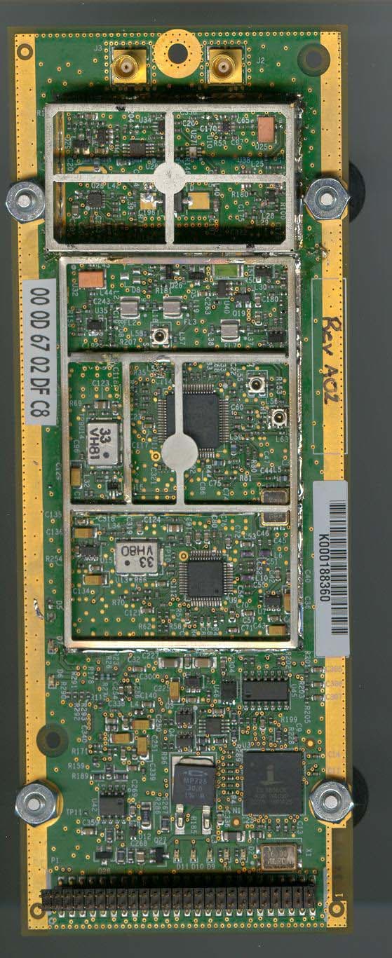
Click to zoom
Application Details
- Equipment Class
- DTS - Digital Transmission System
- Date of Grant
- Sep 29, 2003
- Application Purpose
- Original Equipment
- Date of Application
- Sep 29, 2003
- Equipment Note
- BEL20000 2.4GHz WLAN Radio Module
- Frequency Range
- 2412.00000000 - 2462.00000000
- Company
- Ericsson Wi-Fi
- Country
- United States
Documents & Files
Document Text
Text extracted from the exhibit documents filed with the FCC. Open a document above to read the original.
Users Manual
Page 1 of 12 BEL20000 BEL20000 Product Manual 2.4 GHz WLAN Radio Module Document Date: September 2003 Document Number: PM20000-001 Document Version Number: 2 Document Status: Release © Copyright 2003 by BelAir Networks. All rights reserved.. BEL20000 Product Manual – 2.4 GHz WLAN Radio Module September 2003 Page 2 of 12 PM20000-001 version 2 Contents About this Document ............................................................. 2 Introduction ............................................................................. 3 Conditions of Use .................................................................... 4 Module Installation and Service ............................................ 6 Final Product Requirements .................................................. 7 Regulatory Statements........................................................... 9 About this Document This document is a product manual for the BEL20000 2.4 GHz WLAN Radio Module, including its limitations on use in any product marketed or offered for sale. It is intended as a supplement to training and documentation by BelAir Networks Inc. or its authorized agents. BEL20000 Product Manual – 2.4 GHz WLAN Radio Module September 2003 Page 3 of 12 PM20000-001 version 2 Introduction The BEL20000 (hereafter referred to as “the module”) is a 2.4 GHz radio module compatible with the IEEE 802.11 standard for Wireless LAN operation. It is designed to be interoperable with WLAN products which are based on Direct Sequence Spread Spectrum (DSSS) radio technology. The module contains a complete 802.11b radio and Medium Access Control (MAC) protocol engine which allows implementation of an 802.11b access point (AP). The module is not intended for stand-alone operation. It will only be marketed as a complete product, in conjunction with a package, DC power supply and antenna (hereafter referred to as “the product” or the “final product”). Since the module has a BelAir networks proprietary digital interface, it cannot be directly connected to any standard telecommunications or computer devices. It can only be used with final products designed and authorized specifically for that purpose. BEL20000 Product Manual – 2.4 GHz WLAN Radio Module September 2003 Page 4 of 12 PM20000-001 version 2 Conditions of Use General Conditions of Use This manual is intended to supplement training provided by BelAir Networks or authorized parties. The module BEL20000 is only intended for use in BelAir Networks products and is not for sale to the general public as a stand-alone module. Please read this entire document, including the Regulatory Statements section before attempting to install or operate the module. Warning: Any use of BEL20000 in any manner which is not expressly specified within this manual or specifically approved by BelAir Networks or its authorized agents will void the user’s right to operate this module, and is expressly forbidden by BelAir Networks. This includes any modification of the module, installation of the module in a configuration or used with an antenna which is not expressly listed in this document or approved by BelAir Networks. List of Approved Final Products The BEL20000 module is only approved for use in the following BelAir Networks products: • BA200. See BA200 documentation for complete manufacturing instructions. Operation of the module within the products expressly listed above is required to ensure compliance to all FCC and Industry Canada regulations. Any modification of the module, or its use in any configuration not expressly listed above may void the user’s right to operate this module. Country of Use BEL20000 is certified with limited modular approval for use in the United States as an Intentional Radiator as device: FCC ID: RAR20000001 and in Canada as IC: 4674A-20000001. Please read all regulatory statements at the end of this document before any attempt to install or operate this module. BEL20000 Product Manual – 2.4 GHz WLAN Radio Module September 2003 Page 5 of 12 PM20000-001 version 2 The module is only certified for operation in the United States and Canada. Before attempting to install and operate this module in any other country, contact BelAir Networks for approval. Module Labeling One or more labels are applied to the module during manufacture, including a label which identifies the FCC and Industry Canada identification numbers. Do not attempt to remove any labels from the module. BEL20000 Product Manual – 2.4 GHz WLAN Radio Module September 2003 Page 6 of 12 PM20000-001 version 2 Module Installation and Service Installation into a Product The module shall only be installed by a technician trained by BelAir Networks or its authorized agents. It should only be installed into an approved product (see above) following all manufacturing and service procedures for that product. The module should only be installed into a final product in a manufacturing or service depot site. Caution: BEL20000 is an electro-static discharge (ESD) sensitive device. All appropriate ESD measures must be taken when handling the module. Failure to employ appropriate ESD protection may damage the module. Module Service The module is not intended as a field-serviceable unit. It contains no field- replaceable or field-serviceable parts, or any external adjustable mechanisms. The module should only be serviced in a manufacturing or service depot site approved by BelAir Networks or its authorized agents. BEL20000 Product Manual – 2.4 GHz WLAN Radio Module September 2003 Page 7 of 12 PM20000-001 version 2 Final Product Requirements The requirements below apply to any final product in which the BEL20000 module is installed. Antenna Usage BEL20000 module shall only be used in conjunction with the following antenna types: • BelAir Networks model: BEL10012, 8 dBi directional diversity antenna, beamwidth 65 degrees. Warning: Use of this module in conjunction with any antenna not expressly listed above will void authority to install or operate…
Text truncated - open the document above for the full version.
Users Manual
BelAir200 General Availability BelAir200 Installation Guide Document Date: February 19, 2004 Document Number: BDTK20001-A02 Document Status: Standard Security Status: Confidential Customer Support: 613-254-7070 [email protected] © Copyright 2004 by BelAir Networks. The information contained in this document is confidential and proprietary to BelAir Networks. Errors and Omissions Excepted. Specifications may be subject to change. Page 1 of 17 BelAir200 Installation Guide Contents About this Document..................................................................................2 Introduction...................................................................................................3 Mounting the BelAir200..............................................................................8 Regulatory Statements ..............................................................................13 Detailed Table of Contents......................................................................15 About this Document This guide provides the information you need to physically install the BelAir200. Related Documentation The following titles are BelAir reference documents: • BelAir200 Building Coverage Deployment Guidelines • BelAir200 User Guide February 19, 2004 Confidential Page 2 of 17 Document Number BDTK20001-A02 Standard BelAir200 Installation Guide Introduction BelAir Networks recommends that you prepare for the installation of your Belair200 as follows: 1. Verify the contents of your shipping container. Be sure to note any external carton damage with your shipper to facilitate any future warranty claims. See the section ìShipping Contentsî on page 4. 2. Fill out the included Configuration Worksheet to record the important installation and network configuration settings. 3. Analyze your site to determine the optimum mounting location. To assist you, refer to: ó the section ìSite Surveyî on page 6 ó the BelAir200 Building Coverage Deployment Guidelines ó your authorized reseller 4. Mount the Belair200 by following the steps in the procedure the section ìMounting the BelAir200î on page 8. 5. Configure the BelAir200 for operation. Refer to the BelAir200 User Guide. 6. Verify proper operation of the Belair200. WARNING! Only personnel qualified by BelAir Networks or by one of its authorized resellers or channel partners should install the BelAir200. WARNING! This entire document, including the regulatory statements section, should be read before attempting to install or operate the BelAir200. February 19, 2004 Confidential Page 3 of 17 Document Number BDTK20001-A02 Standard BelAir200 Installation Guide Shipping Contents Table 1 describes how the standard BelAir200 items are packaged for shipping. Table 1: BelAir200 Shipping Box Contents 1 (of 2) See Figure 1 on page 5. BelAir200 AC mains power pigtail Quick Configuration Guide Card User Guide on CD-ROM battery unit (if ordered) 2 (of 2) See Figure 2 on page 6. universal mounting bracket threaded nipple lock nut decorative finial hardwall anchors (quantity of 4) 8-inch worm drive (jubilee) clamp (quantity of 2) drill template February 19, 2004 Confidential Page 4 of 17 Document Number BDTK20001-A02 Standard BelAir200 Installation Guide Figure 1: Contents of Box 1,without BelAir200 Unit February 19, 2004 Confidential Page 5 of 17 Document Number BDTK20001-A02 Standard BelAir200 Installation Guide Figure 2: Contents of Box 2, BelAir200 Mounting Kit Site Survey Due to differences in component configurations, physical placement and environmental considerations, every application is unique. BelAir Networks recommends that a site survey be completed to best determine your coverage needs, installation limitations and optimal node configurations. Contact an authorized reseller to help you with this planning. Antenna Type and Placement Proper antenna placement, orientation and selection are critical factors in maximizing network performance. The antennas are typically placed between 5 m and 10 m above ground level; although alternate installations can be used. Additionally, the antennas should be located with clear lines of site to adjacent equipment in the system and free from obstruction by buildings, foliage and passing traffic. WARNING! Only antennas approved by BelAir Networks may be used in conjunction with the BelAir200. Contact BelAir Networks for an up-to-date list of available approved antennas. Use of any other antenna may exceed FCC or Industry February 19, 2004 Confidential Page 6 of 17 Document Number BDTK20001-A02 Standard BelAir200 Installation Guide Canada regulatory requirements and void the operatorís right to operate the radio equipment. WARNING! Installers must ensure the BelAir200 is mounted in such a manner and in such a location that access to the antennas by the general population is minimized. Access to the antennas by the general population should be limited to greater than 20 cm (8 inches) during normal operation. February 19, 2004 Confidential Page 7 of 17 Document Number BDTK20001-A02 Standard BelAir200 Installation Guide Mounting the BelAir200 Only qualified personnel should mount the Belair200. The BelAir200 is designed to be mounted on a surface or structure that is capable of supporting its weight (28 pounds). It is the responsibility of the customer to ensure the strength of the structure to be mounted to. The Belair200 is supplied with a standard mounting kit in Box 2 that accommodates pole or wall mounting in either an upright or upside-down orientation. If your mounting requires a custom solution, contact BelAir Networks. Installation Procedure 1. Remove the Belair200 from its packaging in Box 1. See Figure 3 Figure 3: BelAir200 in its Packaging February 19, 2004 Confidential Page 8 of 17 Document Number BDTK20001-A02 Standard BelAir200 Installation Guide 2. With a Philips screwdriver, remove the two lower plastic covers. There are two screws per cover. Keep these screws because you will use them later. Figur…
Text truncated - open the document above for the full version.
Cover Letter(s)
Response to TCB Findings 1. A complete user's manual with installation instructions is required. The user's manual should warn the users about the requirement of professional installation. A final user’s manual supplied. 2. Please provide specifications of the antenna used. The specifications listed in the user’s manual as well as LMA request letter. 3. Please supply a modular approval request letter covering all the all 8 points listed in DA 00-1407. LMA request letter supplied with reasons. 4. Please specify the label material that will be used on the module. Please see the updated label exhibit.
Cover Letter(s)
Response to FCC Correspondence 9903 1) The filing contains two MPE exhibits each with different powers and antenna gains - please clarify. A new and most accurate MPE calculation is supplied. Please see the final MPE calculation document. This calculation takes the maximum TDD duty-cycle of 95% in account as follows; 27dBm =500mW x 95% = 475mW = 26.77dBm - 0.5dB = 26.27dBm In the previous calculations this duty-cycle was not included. 2) One MPE exhibit mentions TDD duty cycle - please clarify max expected/intended duty cycle. Max Duty-Cycle = 95% 3) User manual states: "The module shall only be installed by a technician trained by BelAir Networks or its authorized agents. It should only be installed into an approved product (see above)" above: "The BEL20000 module is only approved for use in the following BelAir Networks products: - BA200. See BA200 documentation for complete manufacturing instructions." "Adherence to these rules by the professional installer is mandatory. See full installation procedures for the particular product for details." Please submit description or photos or user manual for BA200, and other antenna installation procedures if applicable. BelAir200 Installation Guide is supplied.
External Photos
2.4 GHz Radio Module Top View 2.4 GHz Radio Module Bottom View 2.4 GHz Radio Module Top View, Shields Removed
ID Label/Location Info
BelAir Networks 2.4 GHz Radio Module Label Location Sept 25, 2003 1 Module Labeling The following label shall be permanently affixed to the radio module as follows: FCC ID: RAR20000001 IC: 4674A-20000001 Label size approximately 30 mm x 7 mm. Label material is white polyester with a permanent one-use acrylic adhesive. This is a CSA/UL approved material. Print technique is thermal ink using 400 DPI resolution. The label location shall be as shown in the diagram below: BelAir Networks 2.4 GHz Radio Module Label Location Sept 25, 2003 2 FCC ID: RAR20000001 IC: 4674A-20000001 Radio Module Top View (actual size) Label Location BelAir Networks 2.4 GHz Radio Module Label Location Sept 25, 2003 3 Product Labeling The following permanent label, or one containing equivalent information, must be affixed in a conspicuous location on the exterior of any product containing this module. In addition the label contents shall appear prominently in the final product user manual. This device contains the following: FCC ID: RAR20000001 IC: 4674A-20000001 This device complies with Part 15 of the FCC Rules. Operation is subject to the following two conditions: (1) This device may not cause harmful interference, and (2) This device must accept any interference received, including interference that may cause undesired operation. Label size: a minimum of 40 mm x 20 mm
RF Exposure Info
Prediction of MPE limit at a given distance BelAir Networks,BA200, ARM Equation from page 18 of OET Bulletin 65, Edition 97-01where: S = power density P = power input to the antennaG = power gain of the antenna in the direction of interest relative to an isotropic radiatorR = distance to the center of radiation of the antenna Maximum peak output power at antenna input terminal: 27.00 (dBm) Maximum peak output power at antenna input terminal: 501.1872336 (mW) Antenna gain(typical): 8.5 (dBi) Maximum antenna gain: 7.079457844 (numeric) Prediction distance: 20 (cm) Prediction frequency: 2400-2483.5 (MHz) MPE limit for uncontrolled exposure at prediction frequency: 1 (mW/cm^2) Power density at prediction frequency: 0.705879 (mW/cm^2) Maximum allowable antenna gain: 10.01269855 (dBi) Margin of Compliance: 1.512698554 (dB) 2 4 R PG S π =
RF Exposure Info
BelAir Networks 2.4 GHz Radio Module MPE Engineering Analysis Aug 22, 2003 Engineering Analysis MPE for 2.4 GHz Transceiver FCC ID: RAR20000001 BelAir Networks This analysis was performed as part of the FCC certification requirements for spread spectrum devices, according to the requirements of: FCC part 15.247 (b) (4), and FCC OET Bulletin 65 “Evaluating Compliance with FCC Guidelines for Human Exposure to Radio frequency Electromagnetic Fields”. The measured transmit power values and worst-case maximum antenna gain for the bottom, middle, and highest transmit channel were used for the MPE calculations. Calculations were performed based on FCC OET Bulletin 65. The calculations are performed based on the following formula provided in OET 65: S = EIRP / (4πR 2 ). For R = 20 cm (8 inches) Channel Transmit Power [dBm] Maximum antenna gain [dBi] Maximum EIRP [dBm] Maximum EIRP [mW] Calculated worst-case Power Density [mW/cm 2 ] 1 24.4 8.5 32.9 1949.9 0.39 6 25.5 8.5 34.0 2511.9 0.50 11 26.5 8.5 35.0 3162.3 0.63 This calculation is a worst-case analysis since it assumes the device is continuously transmitting. The device utilizes the 802.11 WLAN protocol which operates in time- division duplex (TDD) mode, so the transmit duty cycle can never be 100% in normal operation. Based on these calculations and using the limit for general population/uncontrolled environment of 1.0 mW/cm 2 at 2.4 GHz, the BelAir Networks DSSS transceiver does not exceed the MPE requirements set forth in documents above, with a minimum safety distance between antenna and operator of 20 cm (8 inches). The equipment therefore fulfills the requirements on power density for general population/uncontrolled exposure and therefore complies with the requirements of FCC Part 15.247 (b) (4) and FCC OET Bulletin 65.
RF Exposure Info
Prediction of MPE limit at a given distance 802.11b Radio, FCC ID# RAR20000001 Equation from page 18 of OET Bulletin 65, Edition 97-01where: S = power density P = power input to the antennaG = power gain of the antenna in the direction of interest relative to an isotropic radiatorR = distance to the center of radiation of the antennaNote: TX power at 95% duty cycle Maximum peak output power at antenna input terminal: 26.27 (dBm) Maximum peak output power at antenna input terminal: 423.642966 (mW) Antenna gain(typical): 8.5 (dBi) Maximum antenna gain: 7.079457844 (numeric) Prediction distance: 20 (cm) Prediction frequency: 2400-2483.5 (MHz) MPE limit for uncontrolled exposure at prediction frequency: 1 (mW/cm^2) Power density at prediction frequency: 0.596664 (mW/cm^2) Maximum allowable antenna gain: 10.74269855 (dBi) Margin of Compliance: 2.242698554 Note:The power delivered to the antenna is reduced by 0.5dB due to cable loss. 2 4 R PG S π =
Test Report
Master: PT15CDST Date: February 12, 2002 Test Report: 3W07096.2 Applicant: BelAir Networks 603 March Road, Ottawa Ont. K2K 2M5 Equipment Under Test: BA200 Wireless LAN Access Radio Module (ARM) (EUT) 2.4GHz Band In Accordance With: FCC Part 15, Subpart C Digitally Modulated Transmitters, 2400-2483.5MHz Tested By: Nemko Canada Inc. 303 River Road, R.R. 5 Ottawa, Ontario K1V 1H2 Authorized By: Kevin Carr, EMC Specialist Date: 26 August 2003 Total Number of Pages: 32 Nemko Canada Inc. FCC PART 15, SUBPART C Digitally Modulated Transmitters PROJECT NO.:3W07096.2 EQUIPMENT:BA200 ARM Page 2 of 32 Table Of Contents Section 1. Summary Of Test Results ..................................................................................3 Section 2. General Equipment Specification ......................................................................5 Section 3. Powerline Conducted Emissions ........................................................................6 Section 4. Occupied Bandwidth .........................................................................................12 Section 5. Peak Power Output ...........................................................................................16 Section 6. Spurious Emissions (Antenna Conducted)......................................................17 Section 7. Spurious Emissions (Radiated) ........................................................................22 Section 8. Transmitter Power Density ..............................................................................26 Section 9. Block Diagrams...................................................................................................30 Section 10. Test Equipment List ...........................................................................................32 Nemko Canada Inc. FCC PART 15, SUBPART C Digitally Modulated Transmitters PROJECT NO.:3W07096.2 EQUIPMENT:BA200 ARM Page 3 of 32 Section 1. Summary Of Test Results General All measurements are traceable to national standards. These tests were conducted on a sample of the equipment for the purpose of demonstrating compliance with FCC Part 15, Subpart C, Paragraph 15.247 for Digitally Modulated Transmitters. THIS TEST REPORT RELATES ONLY TO THE ITEM(S) TESTED. THE FOLLOWING DEVIATIONS FROM, ADDITIONS TO, OR EXCLUSIONS FROM THE TEST SPECIFICATIONS HAVE BEEN MADE. See “ Summary of Test Data”. TESTED BY: ______________________________ DATE: 26 August 2003 Glen Westwell, Wireless Technologist TESTED BY: ______________________________ DATE: 26 August 2003 Daniel Hynes, EMC Specialist Nemko Canada Inc. authorizes the above named company to reproduce this report provided it is reproduced in its entirety and for use by the company’s employees only. Any use which a third party makes of this report, or any reliance on or decisions to be made based on it, are the responsibility of such third parties. Nemko Canada Inc. accepts no responsibility for damages, if any, suffered by any third party as a result of decisions made or actions based on this report. This report applies only to the items tested. Nemko Canada Inc. FCC PART 15, SUBPART C Digitally Modulated Transmitters PROJECT NO.:3W07096.2 EQUIPMENT:BA200 ARM Page 4 of 32 Summary Of Test Data Name Of Test Para. No. Result Powerline Conducted Emissions 15.207 (a) Complies Occupied Bandwidth 15.247 (a)(2) Complies Peak Power Output 15.247 (b)(3) Complies Spurious Emissions (Antenna Conducted) 15.247 (c) Complies Spurious Emissions (Radiated) 15.247 (c) Complies Transmitter Power Density 15.247 (d) Complies Test Conditions: Indoor Temperature: 22°C Humidity: 42% Outdoor Temperature: 27°C Humidity: 65% Nemko Canada Inc. FCC PART 15, SUBPART C Digitally Modulated Transmitters PROJECT NO.:3W07096.2 EQUIPMENT:BA200 ARM Page 5 of 32 Section 2. General Equipment Specification Manufacturer: BelAir Networks Model No.: BA200 ARM Serial No.: K000188360 Date Received In Laboratory: 28 July 2003 Nemko Identification No.: #7 Modulation: 802.11b 1Mb/s: DSSS,DBPSK, Barker 2 Mb/s: DSSS,DBPSK, Barker 5.5Mb/s: DSSS,DQPSK,CCK 11Mb/s: DSSS,DQPSK,CCK Transmitter Output Power (rated): 27dBm Transmit Frequency: 2400-2483.5MHz (Band) 2412-2462MHz (DUT) Antenna Gain: 8.5dBi Nemko Canada Inc. FCC PART 15, SUBPART C Digitally Modulated Transmitters PROJECT NO.:3W07096.2 EQUIPMENT:BA200 ARM Page 6 of 32 Section 3. Powerline Conducted Emissions Para. No.: 15.207(a) Test Performed By: Daniel Hynes Date of Test: 20 Aug. 2003 Test Results: Comply. Measurement Data: See Atached Graphs. Nemko Canada Inc. FCC PART 15, SUBPART C Digitally Modulated Transmitters PROJECT NO.:3W07096.2 EQUIPMENT:BA200 ARM Page 7 of 32 Nemko Canada Inc. FCC PART 15, SUBPART C Digitally Modulated Transmitters PROJECT NO.:3W07096.2 EQUIPMENT:BA200 ARM Page 8 of 32 Nemko Canada Inc. FCC PART 15, SUBPART C Digitally Modulated Transmitters PROJECT NO.:3W07096.2 EQUIPMENT:BA200 ARM Page 9 of 32 Nemko Canada Inc. FCC PART 15, SUBPART C Digitally Modulated Transmitters PROJECT NO.:3W07096.2 EQUIPMENT:BA200 ARM Page 10 of 32 Nemko Canada Inc. FCC PART 15, SUBPART C Digitally Modulated Transmitters PROJECT NO.:3W07096.2 EQUIPMENT:BA200 ARM Page 11 of 32 Nemko Canada Inc. FCC PART 15, SUBPART C Digitally Modulated Transmitters PROJECT NO.:3W07096.2 EQUIPMENT:BA200 ARM Page 12 of 32 Section 4. Occupied Bandwidth Para. No.: 15.247(a)(2) Test Performed By: Glen Westwell Date of Test:28 July 2003 Test Results: Complies. Limit: Minimun 6dB BW > 500kHz Measurement Data: See attached plot(s). Channel 6dB Occupied BW (MHz) Ch1, 1Mb/s 11.2 11Mb/s 10.5 Ch.6, 1Mb/s 10.8 11Mb/s 10.8 Ch.11, 1Mb/s 11.2 11Mb/s 10.5 Nemko Canada Inc. FCC PART 15, SUBPART C Digitally Modulated Transmitters PROJECT NO.:3W07096.2 EQUIPMENT:BA200 ARM Page 13 of 32 Nemko Canada Inc. FCC PART 15, SUBPART C Digitally Modulated Transmitters PROJECT NO.:3W07096.2 EQUIPMENT:BA200 ARM Page 14 of 32 Nemko Canada Inc. FCC PART 15, SUBPART C Digitally Modulated Transmitters PROJECT NO.:3W07096.2…
Text truncated - open the document above for the full version.
Test Setup Photos
Nemko Canada Inc. FCC PART 15, SUBPART C Digitally Modulated Transmitters PROJECT NO.:3W07096.2 EQUIPMENT:BA200 ARM Page 6 of 32 Section 3. Powerline Conducted Emissions Para. No.: 15.207(a) Test Performed By: Daniel Hynes Date of Test: 20 Aug. 2003 Test Results: Comply. Measurement Data: See Atached Graphs.
Test Setup Photos
Nemko Canada Inc. FCC PART 15, SUBPART C Digitally Modulated Transmitters PROJECT NO.:3W07096.2 EQUIPMENT:BA200 ARM Page 25 of 32 Radiated Set Up Photo
Contact Information
Applicant
Roland Andrew Smith(R&D Wi-Fi Products)
Test Firm
Nemko Canada Inc.Stuart Beck
Technical Specifications
| # | Rule Parts | Frequency Range | Power Output |
|---|---|---|---|
| 1 | 15C | 2.41 GHz - 2.46 GHz | 500.00 mW |
Other Applications from Ericsson Wi-Fi
RAR80005000
Jul 07, 2014802.11n dual-band WIFI router
Equipment Class
NII - Unlicensed National Information Infrastructure TX
RAR80085008
Jul 02, 2014802.11n dual-band WIFI router
Equipment Class
NII - Unlicensed National Information Infrastructure TX
RAR80005111
Jul 02, 2014802.11n dual-band WIFI router
Equipment Class
DTS - Digital Transmission System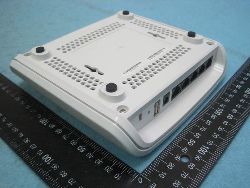
RAR40065006
Nov 30, 2013802.11AC Wireless Router
Equipment Class
NII - Unlicensed National Information Infrastructure TX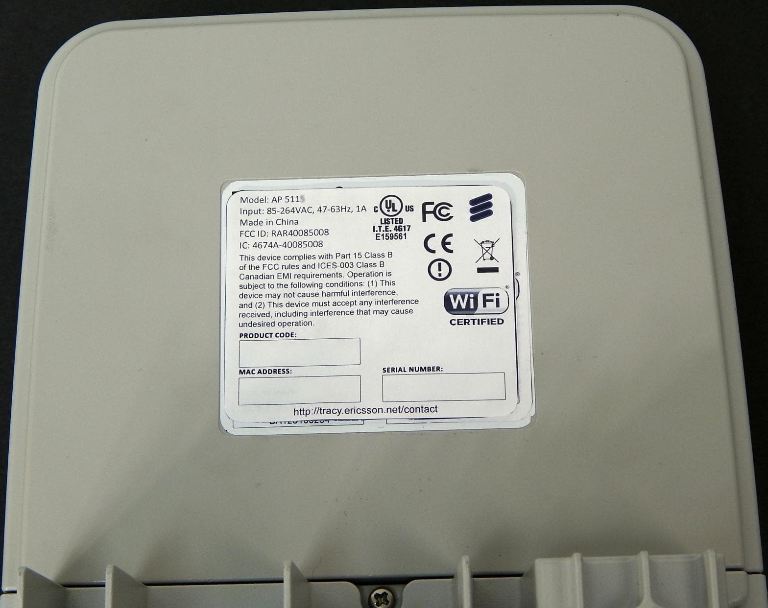
RAR40085008
Oct 28, 2013802.11n dual-band WIFI router
Equipment Class
DTS - Digital Transmission System