RAR80085008802.11n dual-band WIFI router
Ericsson Wi-Fi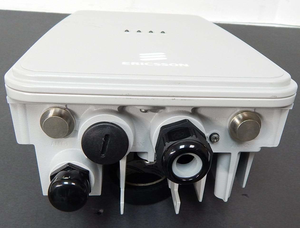
Click to zoom
Application Details
- Equipment Class
- NII - Unlicensed National Information Infrastructure TX
- Date of Grant
- Jul 02, 2014
- Application Purpose
- Original Equipment
- Date of Application
- Jul 02, 2014
- Equipment Note
- 802.11n dual-band WIFI router
- Frequency Range
- 5755.00000000 - 5815.00000000
- Company
- Ericsson Wi-Fi
- Country
- United States
Documents & Files
Document Text
Text extracted from the exhibit documents filed with the FCC. Open a document above to read the original.
Users Manual
BelAir20EO and AP 511x Series Quick Install Guide QUICK GUIDE 1/006 92-LZA 101 803 Uen D Copyright © Ericsson AB 2013. All rights reserved. No part of this document may be reproduced in any form without the written permission of the copyright owner. Disclaimer The contents of this document are subject to revision without notice due to continued progress in methodology, design and manufacturing. Ericsson shall have no liability for any error or damage of any kind resulting from the use of this document. Trademark List Wi-Fi ® Wi-Fi ® is a registered trademark of the Wi-Fi Alliance. Wi-Fi Certified Logo The Wi-Fi CERTIFIED logo is a registered trademark of the Wi-Fi Alliance. Ericsson Ericsson is the trademark or registered trademark of Telefonaktiebolaget LM Ericsson. All other product or service names mentioned in this manual are trademarks of their respective companies. 1/006 92-LZA 101 803 Uen D | 2013-12-13 Getting Started 1Getting Started 1.1Package Contents External antennas are ordered and shipped separately. For AP 5115 to AP 5118: • Customers supply their own power cable and use the power cable connector kit to terminate the cable. • Units can be powered either by AC power or by Power over Ethernet (PoE). 2 1/006 92-LZA 101 803 Uen D | 2013-12-13 BelAir20EO and AP 511x Series Quick Install Guide 1.2AC Power (AP 5115 to AP 5118 Only) These units accept AC input power in the range of 100–240 V AC. The units do not have a power switch. They are powered on when connected to a power source. Maximum AC power consumption is 14.5 W. Warning! The unit contains a 5-A fuse and relies on the rated fuse or circuit breaker of the wall outlet (15 A in North America, 10 A in Europe). Warning! Use ONLY the Ericsson power cable connector supplied with the unit. Use of any other power cable connector can damage the unit and voids the Ericsson product warranty. 1.3Internet Port and Power The unit can be powered with IEEE 802.3af or IEEE 802.3at Power over Ethernet (PoE). Use IEEE 802.3af PoE for most applications. IEEE 802.3af PoE supplies a maximum of 12.95 W to the powered device. Table 1 PoE Power Consumption Table StatePoEPort Only PoEPort and OneLAN Port Idle3.6 W4.05 W Medium Traffic8.4 W8.85 W High Traffic10.8 W11.25 W Max. Traffic11.76 W12.21 W The PoE switch or power injector must meet local and national regulatory requirements. 802.3at Power Source Equipment (PSE) Specification: • 50.0 to 57 V DC, with 30 W output power from the PSE 3 1/006 92-LZA 101 803 Uen D | 2013-12-13 Getting Started 802.3at Powered Device (PD) Specification: • 42.5 to 57 V DC at the PD, with 25.5 W maximum input power to the PD 802.3at Cable Specification: • 100 m maximum length • Maximum cable pair resistance of 12.5 Ohms, satisfied by using CAT5 or CAT5e as specified by ANSI/TIA/EIA-568 or Class D as specified by ISO/IEC 11801:1995 • 600 mA maximum current per pair 1.4Functional Earth Ground and Lightning Protection Units are not designed to survive a direct lightning hit. However, they are intended to withstand the voltage and current surges induced from nearby lightning activity. The level of required lightning protection depends on regional lightning conditions and location of installation. For example, an AP installed on a roof top requires greater lightning protection than an AP installed on the side of a building. The following is a list of recommended installation practices to mitigate the voltage and current surges induced from lightning activity. If there is a conflict between these recommendations and local or national electrical codes, the local or national electrical codes must be followed. • For streetlight or hydro/telecom pole mounting the AC power adapter should be protected with a lightning surge protector. AC power routed to the power adapter must be routed inside the pole. If power is routed on the pole exterior, the power must be routed through a metal conduit grounded at the base of the pole. • For rooftop installations, the unit must not be mounted at the highest point on the building. If the building has installed lightning arrestors, the unit must be located within the umbrella protection zone—a 60 degree zone under the lighting arrestor, but if possible, the unit should not be located closer than 30 feet (approx. 10 m) from the lightning arrestor. Power and Ethernet cables must be routed through independent grounded metal conduits. • For lightning surge protection, the installer must connect a separate ground wire between the external chassis of the unit and a ground on the pole. The ground point on the AP accepts a 1 /4” screw. • It is recommended for areas susceptible to lightning activity, such as on poles, rooftops, or on or near any tall structures, that shielded CAT 5e or CAT 6 Ethernet cable be employed. • The external antennas ports of the unit require lightning arrestors to be employed whenever the external antenna is located more than 3 feet 4 1/006 92-LZA 101 803 Uen D | 2013-12-13 BelAir20EO and AP 511x Series Quick Install Guide (approx. 1 m) from the unit. When lightning arrestors are used, they must be located within 3 feet (approx. 1 m) of the unit and must be grounded to both the unit and protective earth ground. The 1 /4” GND screw of the unit can be used for this application. 5 1/006 92-LZA 101 803 Uen D | 2013-12-13 Installing the BelAir20EO and AP 511x Series AP 2Installing the BelAir20EO and AP 511x Series AP 2.1Step 1—Select Location Choose a proper place for the unit. In general, the best location is at the center of the intended wireless coverage area, within line of sight of all wireless devices. For optimum performance, consider these guidelines: • Mount the unit as high as possible above any obstructions in the coverage area. • Avoid mounting next to or near building support columns or other obstructions that can cause reduced signal or null zones in parts of the coverage area. • Mount away from any signal absorbing or reflecting structures (such as those contai…
Text truncated - open the document above for the full version.
Cover Letter(s)
DATE: June 13, 2014 Nemko Canada Inc. 303 River Road Ottawa, Ontario, Canada K1V 1H2 FCC ID: RAR80085008 Product Name: AP 511X Request for Confidentiality Pursuant to Sections 0.457 and 0.459 of the commission’s rules, we hereby request that the following documents be held confidential: • Schematics • Block diagram These materials contain trade secrets and proprietary information and are not customarily released to the public. The public disclosure of this information might be harmful to the company and provide unjustified benefits to our competitors. Dated this 13 th day of June 2014, By: Marcel Chenier , Head of R&D Wi-Fi Products, LW Ericsson WiFi Inc 6300 Legacy Drive Plano, Texas 75024 Phone: 1 972 583 0000
Cover Letter(s)
Nemko Canada Inc 303 River Road Ottawa, Ontario, Canada K1V 1H2 Attn: Director of Certification Authority to Act as Agent FCC On our behalf, I appoint Jenny Gibbs of Nemko USA, Inc. 2650 FM 407, Suite 255P Bartonville, TX 76226, to act as our agent in the preparation of this application for equipment certification. I certify that submitted documents properly describe the device or system for which equipment certification is sought. I also certify that each unit manufactured, imported or marketed, as defined in FCC regulations will have affixed to it a label identical to that submitted for approval with this application. In signing this letter, Applicant certifies that neither the applicant nor any party to the application is not subject to a denial of Federal benefits, that include FCC benefits, pursuant to Section 5301 of the Anti- Drug Abuse Act of 1988, 21 U.S.C. § 862 because of a conviction for possession or distribution of a controlled substance. See 47 CFR 1.2002(b) for the definition of a "party" for these purposes. For instances where our authorized agent signs the application for certification on our behalf, I acknowledge that all responsibility for complying with the terms and conditions for certification, as specified by Nemko Canada Inc, still resides with Ericsson WiFi, 6300 Legacy Drive Plano Texas 75024. Dated: June 13, 2014 Agency agreement expiration date: June 13, 2015 By: Marcel Chenier_______ Title: Head, R&D Wi-Fi products, LW___ Name of Company: Ericsson WiFi Inc Telephone: 1 972 583 0000
External Photos
External photos Page 1 External photos Applicant: Ericsson WiFi Inc. Model: AP 511X (AP 5115, AP 5116, AP 5117, AP 5118) External photos Page 2 1. Top view External photos Page 3 2. Bottom view with label External photos Page 4 3. Interface view
ID Label/Location Info
Model: AP 5115 Input: 85-264VAC, 47-63Hz, 1A Made in China FCC ID: RAR80085008 Model: AP 5115 Input: 85-264VAC, 47-63Hz, 1A Made in China FCC ID: RAR80085008 IC: 4674A-40085008 http://tracy.ericsson.net/contact http://tracy.ericsson.net/contact This device complies with Part 15 Class B of the FCC rules and ICES-003 Class B Canadian EMI requirements. Operation is subject to the following conditions: (1) This device may not cause harmful interference, and (2) This device must accept any interference received, including interference that may cause undesired operation. This device complies with Part 15 Class B of the FCC rules. Operation is subject to the following conditions: (1) This device may not cause harmful interference, and (2) This device must accept any interference received, including interference that may cause undesired operation. Model: AP 5116 Input: 85-264VAC, 47-63Hz, 1A Made in China FCC ID: RAR80085008 Model: AP 5116 Input: 85-264VAC, 47-63Hz, 1A Made in China FCC ID: RAR80085008 IC: 4674A-40085008 http://tracy.ericsson.net/contact http://tracy.ericsson.net/contact This device complies with Part 15 Class B of the FCC rules and ICES-003 Class B Canadian EMI requirements. Operation is subject to the following conditions: (1) This device may not cause harmful interference, and (2) This device must accept any interference received, including interference that may cause undesired operation. This device complies with Part 15 Class B of the FCC rules. Operation is subject to the following conditions: (1) This device may not cause harmful interference, and (2) This device must accept any interference received, including interference that may cause undesired operation. Model: AP 5117 Input: 85-264VAC, 47-63Hz, 1A Made in China FCC ID: RAR80085008 Model: AP 5117 Input: 85-264VAC, 47-63Hz, 1A Made in China FCC ID: RAR80085008 IC: 4674A-40085008 http://tracy.ericsson.net/contact http://tracy.ericsson.net/contact This device complies with Part 15 Class B of the FCC rules and ICES-003 Class B Canadian EMI requirements. Operation is subject to the following conditions: (1) This device may not cause harmful interference, and (2) This device must accept any interference received, including interference that may cause undesired operation. This device complies with Part 15 Class B of the FCC rules. Operation is subject to the following conditions: (1) This device may not cause harmful interference, and (2) This device must accept any interference received, including interference that may cause undesired operation. Model: AP 5118 Input: 85-264VAC, 47-63Hz, 1A Made in China FCC ID: RAR80085008 Model: AP 5118 Input: 85-264VAC, 47-63Hz, 1A Made in China FCC ID: RAR80085008 IC: 4674A-40085008 http://tracy.ericsson.net/contact http://tracy.ericsson.net/contact This device complies with Part 15 Class B of the FCC rules and ICES-003 Class B Canadian EMI requirements. Operation is subject to the following conditions: (1) This device may not cause harmful interference, and (2) This device must accept any interference received, including interference that may cause undesired operation. This device complies with Part 15 Class B of the FCC rules. Operation is subject to the following conditions: (1) This device may not cause harmful interference, and (2) This device must accept any interference received, including interference that may cause undesired operation. Label Location
Internal Photos
Internal photos Page 1 Internal photos Applicant: Ericsson WiFi Inc. Model: AP 511X (AP 5115, AP 5116, AP 5117, AP 5118) Internal photos Page 2 1. Top general view Internal photos Page 3 2. Top PCB view Internal photos Page 4 3. Top PCB view with removed shielding Internal photos Page 5 4. Bottom PCB view Internal photos Page 6 5. 5 GHz module view Internal photos Page 7 6. 2.4 GHz module view Internal photos Page 8 7. PCB case and power supply location view Internal photos Page 9 8. Antenna compartment front view
Operational Description
Page 1 of 1 Configuration Controls Description Model: AP 511X (AP 5115, AP 5116, AP 5117, AP 5118) The device complies with the requirement of KDB 594280 D01 Configuration Control v02. The SW and radios are Ericsson proprietary. The SW is updated through an Ericsson controller (a closed system). Ericsson introduces new SW through an EC process after a complete SW validation process. Ericsson uses proprietary radio that can only runs Ericsson SW. This is available through secure Ericsson technical support. The domain setting of US is locked into the manufacturing data and cannot be changed. This prevents any third parties operating a US sold device on any other regulatory domain, frequencies, or in any manner that is in violation of the certification, and also prevents third parties from loading non-US versions of the software on the device. And the device is also password protected. The device drivers that set channels and country are embedded into the SW load build and not accessible to any user. Only the professional installers are able to set the radio frequency parameters of Transmit power, operating channel and modulation type. Only authorized parameters are available and can be selected in software. For more details, please refer to the document of Software Security Description.
Operational Description
Page 1 of 1 Operational Description AP 5115/5116/5117/5118 is a WIFI router of dual-radio design which supports both 2.4GHz and 5GHz operation simultaneously with 2x2 MIMO and 2 spatial streams per band. Each stream supports a peak rate of 150 Mbps, thereby providing 300 Mbps per radio and 600 Mbps per access point. Both radios are compliant to IEEE 802.11n-2009 standards. The 2.4 GHz radio also provides full backwards compatibility for IEEE 802.11b and IEEE 802.11g clients. The 5 GHz radio is compatible with IEEE 802.11a clients. The device including transmitter is powered by 48VDC supplied externally via PoE (Power over Ethernet) or AC powering through the dedicated AC Power Input. The radio utilizes the following antenna configurations for the 2.4GHz and 5GHz radios: • 2.4 GHz internal omni + 5 GHz internal omni. This configuration employs four internal omni antennas—two at 2.4 GHz (4.4dBi) and two at 5 GHz (6.7dBi). Variant: AP 5115 • 2.4 GHz internal omni + 5 GHz internal directional. This configuration employs two 2.4 GHz 4.4dBi internal omni antennas, and two 5 GHz 11.5 dBi internal directional antennas. Variant: AP 5116 • 2.4 GHz internal directional + 5 GHz external directional. This configuration employs two 2.4 GHz 8dBi internal cross polarized directional antennas, and two 5 GHz 11.5dBi external cross polarized directional antennas accessible through the two bulkhead N-connectors. Variant: AP 5117 • 2.4 GHz external directional + 5 GHz internal directional. This configuration employs two 2.4 GHz 8dBi external cross polarized directional antennas, and two 5 GHz 11.5dBi internal cross polarized directional antennas accessible through the two bulkhead N-connectors. Variant: AP 5118 Please see user’s manual for additional information. Data transmission is always initiated by software, passed down through the MAC, then to the digital and analog baseband and finally to the RF chips. Several special packets (ACK, CTS, PSPoll, etc.) are initiated by the MAC. These are the only ways the digital baseband circuitry will turn on the RF transmitter, which then turns off at the end of the packet. Therefore the transmitter will only be on while one of the aforementioned packets is being transmitted.
Parts List/Tune Up Info
Page 1 of 3 Software Security Declaration Model: AP 511X (AP 5115, AP 5116, AP 5117, AP 5118) This device is fully compliant with the requirement of KDB 594280 D02 U-NII Device Security v01. SOFTWARE SECURITY DESCRIPTION General Description 1. Describe how any software/firmware update will be obtained, downloaded, and installed. Ericsson introduces new SW through an EC process after a complete SW validation process. Ericsson uses proprietary radio that can only runs Ericsson SW. This is available through secure Ericsson technical support. 2. Describe all the radio frequency parameters that are modified by any software/firmware without any hardware changes. Are these parameters in some way limited, such that, it will not exceed the authorized parameters? All the radio frequency parameters are Transmit power, operating channel, modulation type. Only authorized parameters are available and can be set in software. 3. Are there any authentication protocols in place to ensure that the source of the software/firmware is legitimate? If so, describe in details; if not, explain how the software is secured from modification. The Ericsson SW runs a load validation during the SW upgrade process to ensure that the SW is legitimate, unaltered, and downloaded correctly. The SW, radios, and load validation are proprietary. 4. Are there any verification protocols in place to ensure that the software/firmware is legitimate? If so, describe in details. Software image contains ‘MD5’ signature and contains platform type imbedded in header. 5. Describe, if any, encryption methods used. Software images are not encrypted but are compressed. 6. For a device that can be configured as a master and client (with active or passive scanning), explain how the device ensures compliance for each mode? In particular if the device acts as master in some band of operation and client in another; how is compliance ensured in each band of operation? The device is only a master. Third Party Access Control 1. How are unauthorized software/firmware changes prevented? The SW and radios are Ericsson proprietary. The SW is updated through an Ericsson controller (a closed system). 2. Is it possible for third parties to load device drivers that could modify the RF parameters, country of operation or other parameters which impact device No, the APs are password protected. The device drivers that set channels and country are embedded into the SW load build and not accessible to any user. Page 2 of 3 compliance? If so, describe procedures to ensure that only approved drivers are loaded. It is a proprietary system. The memory maps, SW algorithms are not published. 3. Explain if any third parties have the capability to operate a US sold device on any other regulatory domain, frequencies, or in any manner that is in violation of the certification The access points sold to the US cannot be operated on any other country or domains. This is locked into the manufacturing data and cannot be changed. 4. What prevents third parties from loading non-US versions of the software/firmware on the device? The devices are HW configured to only accept US SW loads only at the time of manufacture, and not changeable. 5. For modular devices, describe how authentication is achieved when used with different hosts. This is not a modular device. SOFTWARE CONFIGURATION DESCRIPTION User Configuration Guide 1. To whom is the UI accessible? (Professional installer, end user, other.) The UI is accessible to the professional installer. a) What parameters are viewable to the professional installer/end-user? The professional installer can change the RF channel and Tx power levels. b) What parameters are accessible or modifiable to the professional installer? The RF channel can only be set to FCC approved channels. The TX power level can be set up to the approved RF power levels (or less). i) Are the parameters in some way limited, so that the installers will not enter parameters that exceed those authorized? Yes, all radio parameters are limited by SW settings pre-determine by the FCC radio regulatory approval process. These parameters are in a drop-down list in the GUI and cannot go outside of these approved values. ii) What controls exist that the user cannot operate the device outside its authorization in the U.S.? The radios are configured at manufacturing to be US only and only Ericsson US SW loads can be installed. These loads control the limits of the operation of the radio. c) What configuration options are available to the end-user? Not available to the end user. i) Are the parameters in some way limited, so that the installers will not enter parameters that exceed those authorized? Yes, all radio parameters are limited by SW settings pre-determine by the FCC radio regulatory approval process. These parameters are in a drop-down list in the GUI and cannot go outside of these approved values. ii) What controls exist that the user cannot operate the device outside its authorization in the U.S.? The radios are configured at manufacturing to be US only and only Ericsson US SW loads can be installed. These loads control the limits of the operation of the radio. d) Is the country code factory set? Can it Yes the country code is factory set. It Page 3 of 3 be changed in the UI? cannot be changed in the UI. i) If so, what controls exist to ensure that the device can only operate within its authorization in the U.S.? The radios are configured at manufacturing to be US only and only Ericsson US SW loads can be installed. e) What are the default parameters when the device is restarted? The device goes to a default (approved) Tx channel and power level based on factory country setting. 2. Can the radio be configured in bridge or mesh mode? If yes, an attestation may be required. Further information is available in KDB Publication 905462 D02. This approval is for UNII-3 band and this KDB applies only to UNII-2A and UNII-2C. 3. For a device that can be configured as a master …
Text truncated - open the document above for the full version.
RF Exposure Info
Prediction of MPE limit at a given distance Equation from page 18 of OET Bulletin 65, Edition 97-01 where:S = power density P = power input to the antenna G = power gain of the antenna in the direction of interest relative to an isotropic radiator R = distance to the center of radiation of the antenna Maximum peak output power at device output terminal:25.76(dBm) Cable and Jumper loss0.0(dB) Maximum peak output power at antenna input terminal:25.76(dBm) Maximum peak output power at antenna input terminal:376.703799(mW) Antenna gain(typical):12(dBi) Maximum antenna gain:15.84893192(numeric) Prediction distance:30(cm) Prediction frequency:2437(MHz) MPE limit for uncontrolled exposure at prediction frequency:1(mW/cm^2) Power density at prediction frequency:0.527895(mW/cm^2) 5.278951(W/m^2) Tx On time:1.000000 Tx period time:1.000000 Average Factor:100.000000 Average Power density at prediction frequency:5.278951(W/m^2) Maximum allowable antenna gain:14.77452373(dBi) Margin of Compliance:2.774523735 dB 2 4R PG S π =
RF Exposure Info
Prediction of MPE limit at a given distance Equation from page 18 of OET Bulletin 65, Edition 97-01 where:S = power density P = power input to the antenna G = power gain of the antenna in the direction of interest relative to an isotropic radiator R = distance to the center of radiation of the antenna Maximum peak output power at device output terminal:22.89(dBm) Cable and Jumper loss0.0(dB) Maximum peak output power at antenna input terminal:22.89(dBm) Maximum peak output power at antenna input terminal:194.5360082(mW) Antenna gain(typical):12(dBi) Maximum antenna gain:15.84893192(numeric) Prediction distance:25(cm) Prediction frequency:5785(MHz) MPE limit for uncontrolled exposure at prediction frequency:1(mW/cm^2) Power density at prediction frequency:0.392564(mW/cm^2) 3.925637(W/m^2) Tx On time:1.000000 Tx period time:1.000000 Average Factor:100.000000 Average Power density at prediction frequency:3.925637(W/m^2) Maximum allowable antenna gain:16.06089881(dBi) Margin of Compliance:4.060898814 dB 2 4R PG S π =
RF Exposure Info
Prediction of MPE limit at a given distance Equation from page 18 of OET Bulletin 65, Edition 97-01 where:S = power density P = power input to the antenna G = power gain of the antenna in the direction of interest relative to an isotropic radiator R = distance to the center of radiation of the antenna Maximum peak output power at device output terminal:25.85(dBm) Cable and Jumper loss0.0(dB) Maximum peak output power at antenna input terminal:25.85(dBm) Maximum peak output power at antenna input terminal:384.591782(mW) Single Antenna gain(typical):11.5(dBi) Number of Antennae1(uncorelated antennas) Total Antenna gain(typical):11.5(dBi) Maximum antenna gain:14.12537545(numeric) Prediction distance:30(cm) Prediction frequency:5785(MHz) MPE limit for uncontrolled exposure at prediction frequency:1(mW/cm^2) Power density at prediction frequency:0.480339(mW/cm^2) 4.803388(W/m^2) Tx On time:1.000000 Tx period time:1.000000 Average Factor:100.000000 Average Power density at prediction frequency:4.803388(W/m^2) Maximum allowable antenna gain:14.68452373(dBi) Margin of Compliance:3.184523735 dB 2 4R PG S π =
Test Report
www.nemko.com Nemko Canada Inc., a testing laboratory, is accredited by the Standards Council of Canada. The tests included in this report are within the scope of this accreditation FCC 15.407 and RSS-210 A9.docx; Date: May 2013 SCC Accredited LAB LAB Accrédité CCN TM ONE WORLDOURAPPROVAL Test report 261299-1TRFWL Date of issue: July 3, 2014 Applicant: Ericsson WiFi Inc. Product: Wi-Fi Access Point Model: Model variant: AP 511x AP 5115, AP 5116, AP 5117, AP 5118, AP 5119 FCC ID: IC Registration number: RAR80085008 4674A-40085008 Specifications: FCC 47 CFR Part 15 Subpart E, §15.407 Unlicensed National Information Infrastructure Devises RSS-210, Issue 8, December 2010, Annex 9 Local Area Network Devices Report reference ID: 261299-1TRFWL Page 2 of 63 Test location Company name: Nemko Canada Inc. Address: 303 River Road City: Ottawa Province: Ontario Postal code: K1V 1H2 Country: Canada Telephone: +1 613 737 9680 Facsimile: +1 613 737 9691 Toll free: +1 800 563 6336 Website: www.nemko.com Site number: FCC: 176392; IC: 2040A-4 (3 m semi anechoic chamber) Tested by: Andrey Adelberg, Senior Wireless/EMC Specialist Reviewed by: Kevin Rose, Wireless/EMC Specialist Date: July 3, 2014 Signature: Limits of responsibility Note that the results contained in this report relate only to the items tested and were obtained in the period between the date of initial receipt of samples and the date of issue of the report. This test report has been completed in accordance with the requirements of ISO/IEC 17025. All results contain in this report are within Nemko Canada’s ISO/IEC 17025 accreditation. Copyright notification Nemko Canada Inc. authorizes the applicant to reproduce this report provided it is reproduced in its entirety and for use by the company’s employees only. Any use which a third party makes of this report, or any reliance on or decisions to be made based on it, are the responsibility of such third parties. Nemko Canada Inc. accepts no responsibility for damages, if any, suffered by any third party as a result of decisions made or actions based on this report. © Nemko Canada Inc. Report reference ID: 261299-1TRFWL Page 3 of 63 Table of contents Table of contents .......................................................................................................................................................................................................... 3 Section 1. Report summary ................................................................................................................................................................................. 4 1.1 Applicant and manufacturer .................................................................................................................................................................................... 4 1.2 Test specifications .................................................................................................................................................................................................... 4 1.3 Test methods ............................................................................................................................................................................................................ 4 1.4 Statement of compliance ......................................................................................................................................................................................... 4 1.5 Exclusions ................................................................................................................................................................................................................. 4 1.6 Test report revision history ...................................................................................................................................................................................... 4 Section 2. Summary of test results ....................................................................................................................................................................... 5 2.1 FCC Part 15 Subpart C, general requirements test results ........................................................................................................................................ 5 2.2 FCC Part 15 Subpart E, test results ........................................................................................................................................................................... 5 2.3 RSS-Gen, Issue 3, test results.................................................................................................................................................................................... 5 2.4 IC RSS-210, Issue 8, test results .......................................…
Text truncated - open the document above for the full version.
Contact Information
Applicant
Roland Andrew Smith(R&D Wi-Fi Products)
Test Firm
Nemko Canada Inc. (Ottawa)Charles Neal
Technical Specifications
| # | Rule Parts | Frequency Range | Power Output |
|---|---|---|---|
| 2 | 15E | 5.75 GHz - 5.82 GHz | 373.00 mW |
Other Applications from Ericsson Wi-Fi
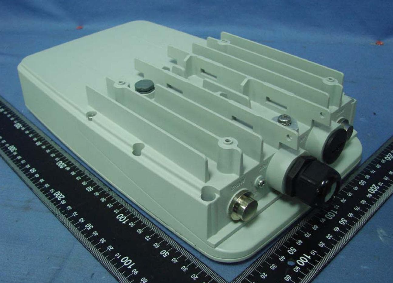
RAR80005000
Jul 07, 2014802.11n dual-band WIFI router
Equipment Class
NII - Unlicensed National Information Infrastructure TX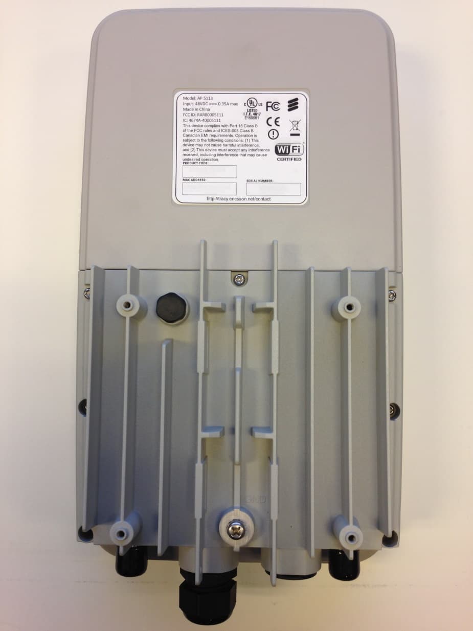
RAR80005111
Jul 02, 2014802.11n dual-band WIFI router
Equipment Class
DTS - Digital Transmission System
RAR40065006
Nov 30, 2013802.11AC Wireless Router
Equipment Class
NII - Unlicensed National Information Infrastructure TX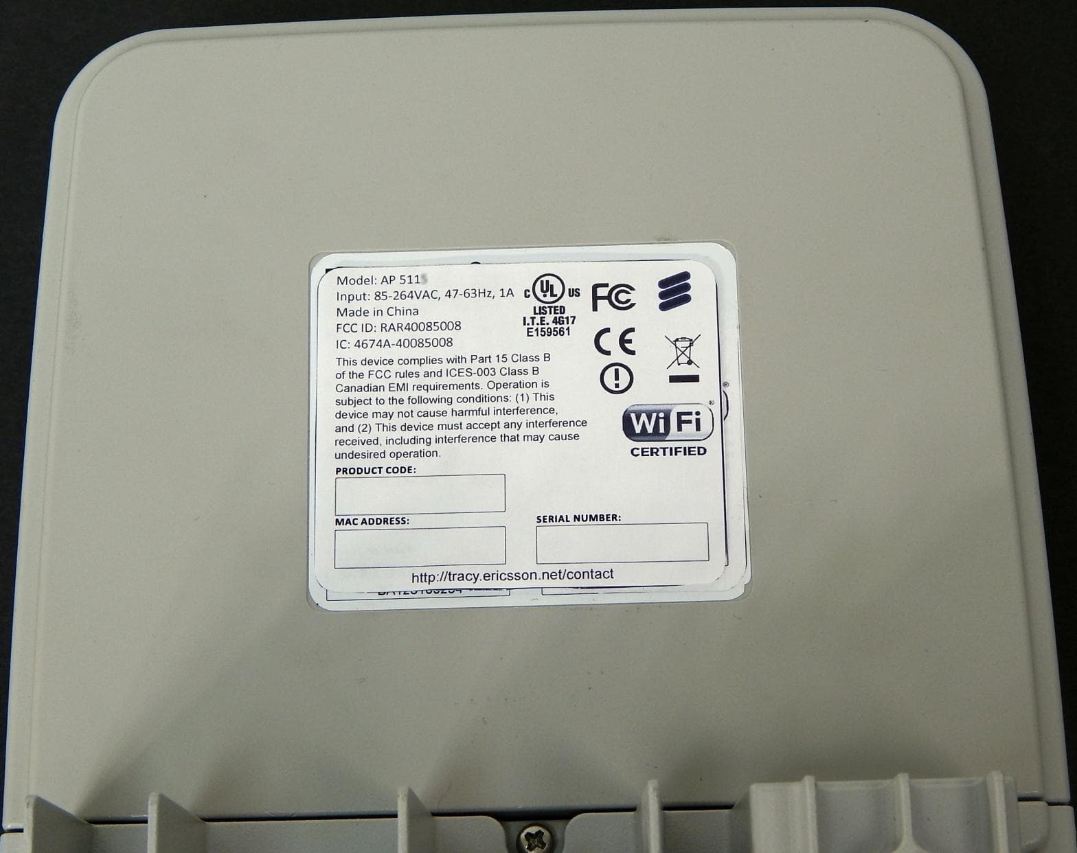
RAR40085008
Oct 28, 2013802.11n dual-band WIFI router
Equipment Class
DTS - Digital Transmission System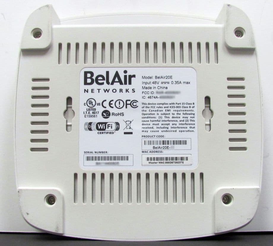
RAR40015001
Nov 20, 2012802.11n dual-band WIFI router
Equipment Class
NII - Unlicensed National Information Infrastructure TX