RAR200000022.4 GHz WLAN Access Radio Module
Ericsson Wi-Fi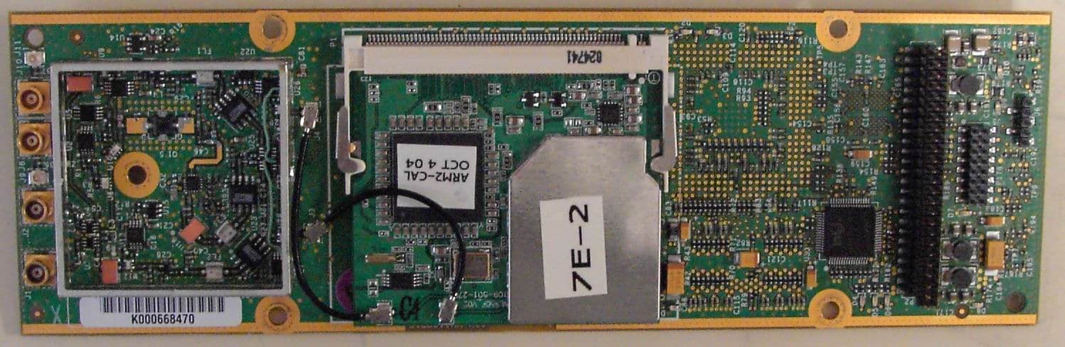
Click to zoom
Application Details
- Equipment Class
- DTS - Digital Transmission System
- Date of Grant
- Nov 23, 2004
- Application Purpose
- Original Equipment
- Date of Application
- Nov 23, 2004
- Equipment Note
- 2.4 GHz WLAN Access Radio Module
- Frequency Range
- 2412.00000000 - 2462.00000000
- Company
- Ericsson Wi-Fi
- Country
- United States
Documents & Files
Document Text
Text extracted from the exhibit documents filed with the FCC. Open a document above to read the original.
Users Manual
Page 1 of 14 B2CC011AA B2CC011AA-A Product Manual 2.4 GHz WLAN Access Radio Module 2 Document Date: November 2004 Document Number: PM-B2CC011AA-A Document Version Number: 2 Document Status: Release © Copyright 2004 by BelAir Networks. All rights reserved.. B2CC011AA-A Product Manual – 2.4 GHz WLAN Radio Module November 2004 Page 2 of 14 PM-B2CC011AA-A Version 2 B2CC011AA-A Product Manual – 2.4 GHz WLAN Radio Module November 2004 Page 3 of 14 PM-B2CC011AA-A Version 2 Contents About this Document ............................................................. 3 Introduction ............................................................................. 3 Conditions of Use .................................................................... 3 Module Installation and Service ............................................ 3 Final Product Requirements .................................................. 3 Regulatory Statements........................................................... 3 About this Document This document is a product manual for the B2CC011AA-A 2.4 GHz WLAN Access Radio Module 2, including its limitations on use in any product marketed or offered for sale. It is intended as a supplement to training and documentation by BelAir Networks Inc. or its authorized agents. B2CC011AA-A Product Manual – 2.4 GHz WLAN Radio Module November 2004 Page 4 of 14 PM-B2CC011AA-A Version 2 Introduction The B2CC011AA-A (hereafter referred to as “the module”) is a 2.4 GHz radio module compatible with the IEEE 802.11 standard for Wireless LAN operation. It is designed to be interoperable with WLAN products which are based on Direct Sequence Spread Spectrum (DSSS) radio technology. The module contains a complete 802.11b/g radio and Medium Access Control (MAC) protocol engine which allows implementation of an 802.11b/g access point (AP). The module is not intended for stand-alone operation. It will only be marketed as a complete product, in conjunction with a package, DC power supply and antenna (hereafter referred to as “the product” or the “final product”). Since the module has a BelAir networks proprietary digital interface, it cannot be directly connected to any standard telecommunications or computer devices. It can only be used with final products designed and authorized specifically for that purpose. B2CC011AA-A Product Manual – 2.4 GHz WLAN Radio Module November 2004 Page 5 of 14 PM-B2CC011AA-A Version 2 Conditions of Use General Conditions of Use This manual is intended to supplement training provided by BelAir Networks or authorized parties. The module B2CC011AA-A is only intended for use in BelAir Networks products and is not for sale to the general public as a stand- alone module. Please read this entire document, including the Regulatory Statements section before attempting to install or operate the module. Warning: Any use of B2CC011AA-A in any manner which is not expressly specified within this manual or specifically approved by BelAir Networks or its authorized agents will void the user’s right to operate this module, and is expressly forbidden by BelAir Networks. This includes any modification of the module, installation of the module in a configuration or used with an antenna which is not expressly listed in this document or approved by BelAir Networks. List of Approved Final Products The B2CC011AA-A module is only approved for use in the following BelAir Networks products: • BelAir200. See BelAir200 documentation for complete manufacturing instructions. • BelAir100. See BelAir100 documentation for complete manufacturing instructions. Operation of the module within the products expressly listed above is required to ensure compliance to all FCC and Industry Canada regulations. Any modification of the module, or its use in any configuration not expressly listed above may void the user’s right to operate this module. Country of Use B2CC011AA-A is certified with limited modular approval for use as an Intentional Radiator in the United States as device: FCC ID: RAR20000002 B2CC011AA-A Product Manual – 2.4 GHz WLAN Radio Module November 2004 Page 6 of 14 PM-B2CC011AA-A Version 2 and in Canada as IC: 4674A-20000002. Please read all regulatory statements at the end of this document before any attempt to install or operate this module. The module is only certified for operation in the United States and Canada. Before attempting to install and operate this module in any other country, contact BelAir Networks for approval. Module Labeling One or more labels are applied to the module during manufacture, including a label which identifies the FCC and Industry Canada identification numbers. Do not attempt to remove any labels from the module. B2CC011AA-A Product Manual – 2.4 GHz WLAN Radio Module November 2004 Page 7 of 14 PM-B2CC011AA-A Version 2 Module Installation and Service Installation into a Product The module shall only be installed by a technician trained by BelAir Networks or its authorized agents. It should only be installed into an approved product (see above) following all manufacturing and service procedures for that product. The module should only be installed into a final product in a manufacturing or service depot site. Caution: B2CC011AA-A is an electro-static discharge (ESD) sensitive device. All appropriate ESD measures must be taken when handling the module. Failure to employ appropriate ESD protection may damage the module. Module Service The module is not intended as a field-serviceable unit. It contains no field- replaceable or field-serviceable parts, or any external adjustable mechanisms. The module should only be serviced in a manufacturing or service depot site approved by BelAir Networks or its authorized agents. B2CC011AA-A Product Manual – 2.4 GHz WLAN Radio Module November 2004 Page 8 of 14 PM-B2CC011AA-A Version 2 Final Product Requirements The requirements below apply to any final product in which the B2CC011AA- A module is installed. Antenna Usage and Module Transmit Power…
Text truncated - open the document above for the full version.
Cover Letter(s)
1 November 18, 2004 Attn: Reviewing Engineer Federal Communications Commission 7435 Oakland Mills Road Columbia, MD 21046 RE: LIMITED MODULAR APPROVAL FOR FCC ID: RAR20000002 AS PER FCC PUBLIC NOTICE DA 00-1407 To Whom It May Concern, The module FCC ID: RAR20000002 is submitted for Limited Modular Approval (LMA) by BelAir Networks Inc. In keeping with FCC Public Notice DA 00-1407, Part 15 Unlicensed Modular Transmitter Approval, this letter affirms that BelAir Networks shall retain complete control over the final installation of the device and ensure compliance of the end-product to FCC regulations. The module shall only be installed into a final product by technicians trained by BelAir Networks. The module shall not be distributed, marketed or sold to the general public. It will only be available installed in a complete BelAir Networks product. The complete BelAir product shall only be sold by BelAir Networks directly or through a BelAir Networks-specified sales channel to authorized resellers, and will be installed by professional installers with training by BelAir Networks or authorized representatives. As illustrated by the accompanying documentation, the module FCC ID: RAR20000002 is a module with its own RF shielding, contains the complete radio within the module, provides its own power supply regulation, was tested in a stand-alone configuration, will be labeled with FCC ID and meets RF exposure regulations. The following is a point-by-point response to the items listed in DA 00- 1407: 1. The module has its own RF shielding. It has been tested for radiated emissions with the module on its own, with no external shielding beyond that incorporated into the module to ensure BelAir Networks U.S. East 11921 Freedom Drive Suite 550 Reston, VA USA 20190 703-736-8306 BelAir Networks U.S. West 1902 Wright Place Suite 200 Carlsbad, CA USA 92008 760-918-5544 [email protected] BelAir Networks Inc. 603 March Road Kanata, Ontario Canada K2K 2M5 613-254-7070 [email protected] www.belairnetworks.com 2 compliance to all radiated emissions requirements at the module level. 2. The input to the module is an Ethernet interface. All modulation and 802.11 protocol elements reside within the module. There are no modulation or data inputs to the module which could alter the performance or behaviour of the modulator or radio which could cause it to exceed FCC limits. 3. The module has its own power supply filtering and regulation for all modulation and radio circuitry in order to avoid any issues with varying power supply inputs. The module is powered by several DC voltage rails. In order to test power line conducted requirements for the module, it was tested with the power supply and package as intended for the complete product which will be manufactured by BelAir Networks. BelAir Networks maintains complete control of the AC-to-DC power supply and packaging of the complete product and therefore ensures that compliance will be maintained. 4. The module incorporates MCX RF connectors and does not have an integral antenna on the module. The module was tested in conjunction with the intended antennas (see accompanying documentation). Considering our submission is seeking Limited Modular Approval, BelAir Networks will ensure professional installation of the complete product. In this manner we will ensure that only the approved antenna type is used in conjunction with this module. 5. The module was tested in a stand-alone configuration for all conducted and radiated emissions, except for conducted power line emissions. Since the module is not AC powered, it was tested with the power supply and package in the configuration with which it will be installed in the product. This configuration is also tested to ensure the complete product will meet all Class B radiated and conducted emissions requirements. 6. The module will be labeled with its own FCC ID number. Since this label will not be visible when the module is installed in the complete product, the manual indicates that the final product shall include a permanent label which uses the wording “Contains FCC ID: RAR20000002”. See the labeling information provided with this submission. 7. The module operates under Part 15.247 (b) (3). Since all modulation and 802.11 protocol elements reside within the BelAir Networks U.S. East 11921 Freedom Drive Suite 550 Reston, VA USA 20190 703-736-8306 BelAir Networks U.S. West 1902 Wright Place Suite 200 Carlsbad, CA USA 92008 760-918-5544 [email protected] BelAir Networks Inc. 603 March Road Kanata, Ontario Canada K2K 2M5 613-254-7070 [email protected] www.belairnetworks.com
ID Label/Location Info
BelAir Networks 2.4 GHz Access Radio Module 2 Label Location November 1, 2004 1 Module Labeling The following label shall be permanently affixed to the radio module as follows: FCC ID: RAR20000002 IC: 4674A-20000002 Label size approximately 30 mm x 7 mm. Label material is white polyester with a permanent acrylic adhesive. This is a CSA/UL approved material. Print technique is thermal ink using 400 DPI resolution. BelAir Networks 2.4 GHz Access Radio Module 2 Label Location November 1, 2004 2 The label location shall be as shown in the diagram below: BelAir Networks 2.4 GHz Access Radio Module 2 Label Location November 1, 2004 3 Product Labeling The following permanent label, or one containing equivalent information, must be affixed in a conspicuous location on the exterior of any product containing this module. In addition the label contents shall appear prominently in the final product user manual. This device contains the following: FCC ID: RAR20000002 IC: 4674A-20000002 This device complies with Part 15 of the FCC Rules. Operation is subject to the following two conditions: (1) This device may not cause harmful interference, and (2) This device must accept any interference received, including interference that may cause undesired operation. Label size: a minimum of 40 mm x 20 mm
RF Exposure Info
Prediction of MPE limit at a given distance 11.5dBi Directional Antenna Equation from page 18 of OET Bulletin 65, Edition 97-01where: S = power density P = power input to the antennaG = power gain of the antenna in the direction of interest relative to an isotropic radiatorR = distance to the center of radiation of the antenna Maximum peak output power at antenna input terminal: 20.00 (dBm) Maximum peak output power at antenna input terminal: 100 (mW) Antenna gain(typical): 11.5 (dBi) Maximum antenna gain: 14.12537545 (numeric) Prediction distance: 25 (cm) Prediction frequency: 2400 (MHz) MPE limit for uncontrolled exposure at prediction frequency: 1 (mW/cm^2) Power density at prediction frequency: 0.179850 (mW/cm^2) Maximum allowable antenna gain: 18.95089881 (dBi) Margin of Compliance: 7.450898814 2 4 R PG S π =
RF Exposure Info
Prediction of MPE limit at a given distance 12dBi Antenna Equation from page 18 of OET Bulletin 65, Edition 97-01where: S = power density P = power input to the antennaG = power gain of the antenna in the direction of interest relative to an isotropic radiatorR = distance to the center of radiation of the antenna Maximum peak output power at antenna input terminal: 19.00 (dBm) Maximum peak output power at antenna input terminal: 79.43282347 (mW) Antenna gain(typical): 12 (dBi) Maximum antenna gain: 15.84893192 (numeric) Prediction distance: 25 (cm) Prediction frequency: 2400 (MHz) MPE limit for uncontrolled exposure at prediction frequency: 1 (mW/cm^2) Power density at prediction frequency: 0.160291 (mW/cm^2) Maximum allowable antenna gain: 19.95089881 (dBi) Margin of Compliance: 7.950898814 2 4 R PG S π =
RF Exposure Info
Prediction of MPE limit at a given distance 4dBi Antenna Equation from page 18 of OET Bulletin 65, Edition 97-01where: S = power density P = power input to the antennaG = power gain of the antenna in the direction of interest relative to an isotropic radiatorR = distance to the center of radiation of the antenna Maximum peak output power at antenna input terminal: 25.40 (dBm) Maximum peak output power at antenna input terminal: 346.7368505 (mW) Antenna gain(typical): 4 (dBi) Maximum antenna gain: 2.511886432 (numeric) Prediction distance: 25 (cm) Prediction frequency: 2400 (MHz) MPE limit for uncontrolled exposure at prediction frequency: 1 (mW/cm^2) Power density at prediction frequency: 0.110895 (mW/cm^2) Maximum allowable antenna gain: 13.55089881 (dBi) Margin of Compliance: 9.550898814 2 4 R PG S π =
RF Exposure Info
Prediction of MPE limit at a given distance 6dBi Antenna Equation from page 18 of OET Bulletin 65, Edition 97-01where: S = power density P = power input to the antennaG = power gain of the antenna in the direction of interest relative to an isotropic radiatorR = distance to the center of radiation of the antenna Maximum peak output power at antenna input terminal: 25.40 (dBm) Maximum peak output power at antenna input terminal: 346.7368505 (mW) Antenna gain(typical): 6 (dBi) Maximum antenna gain: 3.981071706 (numeric) Prediction distance: 25 (cm) Prediction frequency: 2400 (MHz) MPE limit for uncontrolled exposure at prediction frequency: 1 (mW/cm^2) Power density at prediction frequency: 0.175756 (mW/cm^2) Maximum allowable antenna gain: 13.55089881 (dBi) Margin of Compliance: 7.550898814 2 4 R PG S π =
RF Exposure Info
Prediction of MPE limit at a given distance 8dBi Antenna Equation from page 18 of OET Bulletin 65, Edition 97-01where: S = power density P = power input to the antennaG = power gain of the antenna in the direction of interest relative to an isotropic radiatorR = distance to the center of radiation of the antenna Maximum peak output power at antenna input terminal: 23.40 (dBm) Maximum peak output power at antenna input terminal: 218.7761624 (mW) Antenna gain(typical): 8 (dBi) Maximum antenna gain: 6.309573445 (numeric) Prediction distance: 25 (cm) Prediction frequency: 2400 (MHz) MPE limit for uncontrolled exposure at prediction frequency: 1 (mW/cm^2) Power density at prediction frequency: 0.175756 (mW/cm^2) Maximum allowable antenna gain: 15.55089881 (dBi) Margin of Compliance: 7.550898814 2 4 R PG S π =
RF Exposure Info
Prediction of MPE limit at a given distance 8dBi Directional Antenna Equation from page 18 of OET Bulletin 65, Edition 97-01where: S = power density P = power input to the antennaG = power gain of the antenna in the direction of interest relative to an isotropic radiatorR = distance to the center of radiation of the antenna Maximum peak output power at antenna input terminal: 23.40 (dBm) Maximum peak output power at antenna input terminal: 218.7761624 (mW) Antenna gain(typical): 8 (dBi) Maximum antenna gain: 6.309573445 (numeric) Prediction distance: 25 (cm) Prediction frequency: 2400 (MHz) MPE limit for uncontrolled exposure at prediction frequency: 1 (mW/cm^2) Power density at prediction frequency: 0.175756 (mW/cm^2) Maximum allowable antenna gain: 15.55089881 (dBi) Margin of Compliance: 7.550898814 2 4 R PG S π =
Test Report
Master: PT15CDST Date: February 12, 2002 Test Report: 4W31182 Applicant: BelAir Networks 603 March Road, Kanata Ont. K2K 2M5 Equipment Under Test: Wireless LAN Access Radio Module 2 (ARM2) (EUT) 2.4GHz Band FCC ID: RAR20000002 In Accordance With: FCC Part 15, Subpart C Digitally Modulated Transmitters, 2400-2483.5MHz Tested By: Nemko Canada Inc. 303 River Road, R.R. 5 Ottawa, Ontario K1V 1H2 Authorized By: Sim Jagpal, General Manager Date: 8 November 2004 Total Number of Pages: 56 Nemko Canada Inc. FCC PART 15, SUBPART C Digitally Modulated Transmitters PROJECT NO.:4W31182 EQUIPMENT: ARM2 Page 2 of 26 Table Of Contents Section 1. Summary Of Test Results ...................................................................................3 Section 2. General Equipment Specification ......................................................................5 Section 3. Powerline Conducted Emissions ........................................................................6 Section 4. Occupied Bandwidth .........................................................................................10 Section 5. Peak Power Output ...........................................................................................16 Section 6. Spurious Emissions (Antenna Conducted)......................................................17 Section 7. Spurious Emissions (Radiated) ........................................................................22 Section 8. Transmitter Power Density ..............................................................................47 Section 9. RF Exposure Evaluation ...................................................................................52 Section 10. Block Diagrams...................................................................................................54 Section 11. Test Equipment List ...........................................................................................56 Nemko Canada Inc. FCC PART 15, SUBPART C Digitally Modulated Transmitters PROJECT NO.:4W31182 EQUIPMENT: ARM2 Page 3 of 26 Section 1. Summary Of Test Results General All measurements are traceable to national standards. These tests were conducted on a sample of the equipment for the purpose of demonstrating compliance with FCC Part 15, Subpart C, Paragraph 15.247 for Digitally Modulated Transmitters. THIS TEST REPORT RELATES ONLY TO THE ITEM(S) TESTED. THE FOLLOWING DEVIATIONS FROM, ADDITIONS TO, OR EXCLUSIONS FROM THE TEST SPECIFICATIONS HAVE BEEN MADE. See “ Summary of Test Data”. TESTED BY: ______________________________ DATE: 8 November 2004 Glen Westwell, Wireless Specialist Nemko Canada Inc. authorizes the above named company to reproduce this report provided it is reproduced in its entirety and for use by the company’s employees only. Any use which a third party makes of this report, or any reliance on or decisions to be made based on it, are the responsibility of such third parties. Nemko Canada Inc. accepts no responsibility for damages, if any, suffered by any third party as a result of decisions made or actions based on this report. This report applies only to the items tested. Nemko Canada Inc. FCC PART 15, SUBPART C Digitally Modulated Transmitters PROJECT NO.:4W31182 EQUIPMENT: ARM2 Page 4 of 26 Summary Of Test Data Name Of Test Para. No. Result Powerline Conducted Emissions 15.207 (a) Complies Occupied Bandwidth 15.247 (a)(2) Complies Peak Power Output 15.247 (b)(3)(4) Complies Spurious Emissions (Antenna Conducted) 15.247 (d) Complies Spurious Emissions (Radiated) 15.247 (d) Complies Transmitter Power Density 15.247 (e) Complies Note: This certification is for a Limited Modular Approval. Where relevant, test data has been provided in a populated host unit to justify compliance when intergrated. Test Conditions: Indoor Temperature: 22°C Humidity: 39% Outdoor Temperature: 14°C Humidity: 55% Test Set Up Configuration BK Precision Power Supply 3.3Vdc & 5.5Vdc EUT Spec.A 20dB ARM2 Radio Nemko Canada Inc. FCC PART 15, SUBPART C Digitally Modulated Transmitters PROJECT NO.:4W31182 EQUIPMENT: ARM2 Page 5 of 56 Section 2. General Equipment Specification Manufacturer: BelAir Networks Model No.: B2CC011AA Serial No.: K000668470 Date Received In Laboratory: 12 Oct. 2004 Nemko Identification No.: #9 Modulation: 802.11b/g BPSK/CCK/OFDM Transmitter Output Power (max.rated): 26dBm Transmit Frequency: 2400-2483.5MHz (Band) 2412-2462MHz (DUT) Antenna(s) & Gain: 4dBi Maxrad MFB2004 6dBi Maxrad MFB2006 8dBi Maxrad MFB2008 12dBi Maxrad MFB2012 8.5dBi BelAir Directional 11.5dBi BelAir Directional Nemko Canada Inc. FCC PART 15, SUBPART C Digitally Modulated Transmitters PROJECT NO.:4W31182 EQUIPMENT: ARM2 Page 6 of 56 Section 3. Powerline Conducted Emissions Para. No.: 15.207(a) Test Performed By: Dave Duchaines Date of Test: 24 Sept. 2004 Test Results: Complies. Measurement Data: See Atached Graphs. Power line Conducted data was measured in a fully integrated host unit. Nemko Canada Inc. FCC PART 15, SUBPART C Digitally Modulated Transmitters PROJECT NO.:4W31182 EQUIPMENT: ARM2 Page 7 of 56 Conducted Disturbance at Mains Plots Nemko Canada Inc. FCC PART 15, SUBPART C Digitally Modulated Transmitters PROJECT NO.:4W31182 EQUIPMENT: ARM2 Page 8 of 56 Conducted Disturbance at Mains Plots, continued Nemko Canada Inc. FCC PART 15, SUBPART C Digitally Modulated Transmitters PROJECT NO.:4W31182 EQUIPMENT: ARM2 Page 9 of 56 Test Date: September 24, 2004 Engineer’s Name: David Duchesne Tested as per: Table Top Mains Input Voltage: 120VAC Mains Input Frequency: 60Hz Port Investigation Data Port under test: AC Mains Input Results: Refer to plots and table of this section. Conductor Frequency (MHz) Detector Emission Level (dBuV) LISN Loss (dB) Cable Loss (dB) Result (dBuV) Limit (dBuV) Margin (dB) Quasi-Peak 44.8 0.1 0 44.9 66.0 21.1 0.1500 Average 14.4 0.1 0 14.5 56.0 41.5 Quasi-Peak 49 0.1 0 49.1 64.9 15.8 0.1721 Average 44.3 0.1 0 44.4 54.9 10.5 Quasi-Peak 47.4 0 0 47.4 62.5 15.1 0.2295 Average 42.2 0 0 4…
Text truncated - open the document above for the full version.
Test Setup Photos
Nemko Canada Inc. FCC PART 15, SUBPART C Digitally Modulated Transmitters PROJECT NO.:4W31182 EQUIPMENT: ARM2 Page 6 of 56 Section 3. Powerline Conducted Emissions Para. No.: 15.207(a) Test Performed By: Dave Duchaines Date of Test: 24 Sept. 2004 Test Results: Complies. Measurement Data: See Atached Graphs. Power line Conducted data was measured in a fully integrated host unit.
Test Setup Photos
Nemko Canada Inc. FCC PART 15, SUBPART C Digitally Modulated Transmitters PROJECT NO.:4W31182 EQUIPMENT: ARM2 Page 44 of 56 Radiated Set Up Photo 12dBi Omni 8dBi Omni Nemko Canada Inc. FCC PART 15, SUBPART C Digitally Modulated Transmitters PROJECT NO.:4W31182 EQUIPMENT: ARM2 Page 45 of 56 6dBi Omni 8.5dBi Dirrectional Nemko Canada Inc. FCC PART 15, SUBPART C Digitally Modulated Transmitters PROJECT NO.:4W31182 EQUIPMENT: ARM2 Page 46 of 56 11.5dBi Dirrectional
Contact Information
Applicant
Roland Andrew Smith(R&D Wi-Fi Products)
Technical Contact
Non-Technical Contact
BelAir Networks Inc.Stephen Rayment
[email protected]613-254-7070
Test Firm
Nemko Canada Inc. (Ottawa)Charles Neal
Technical Specifications
| # | Rule Parts | Frequency Range | Power Output |
|---|---|---|---|
| 1 | 15C | 2.41 GHz - 2.46 GHz | 398.00 mW |
Other Applications from Ericsson Wi-Fi
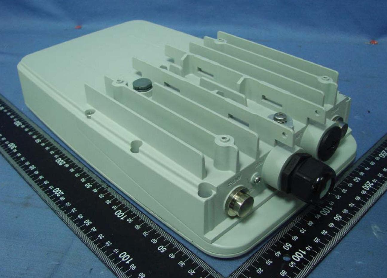
RAR80005000
Jul 07, 2014802.11n dual-band WIFI router
Equipment Class
NII - Unlicensed National Information Infrastructure TX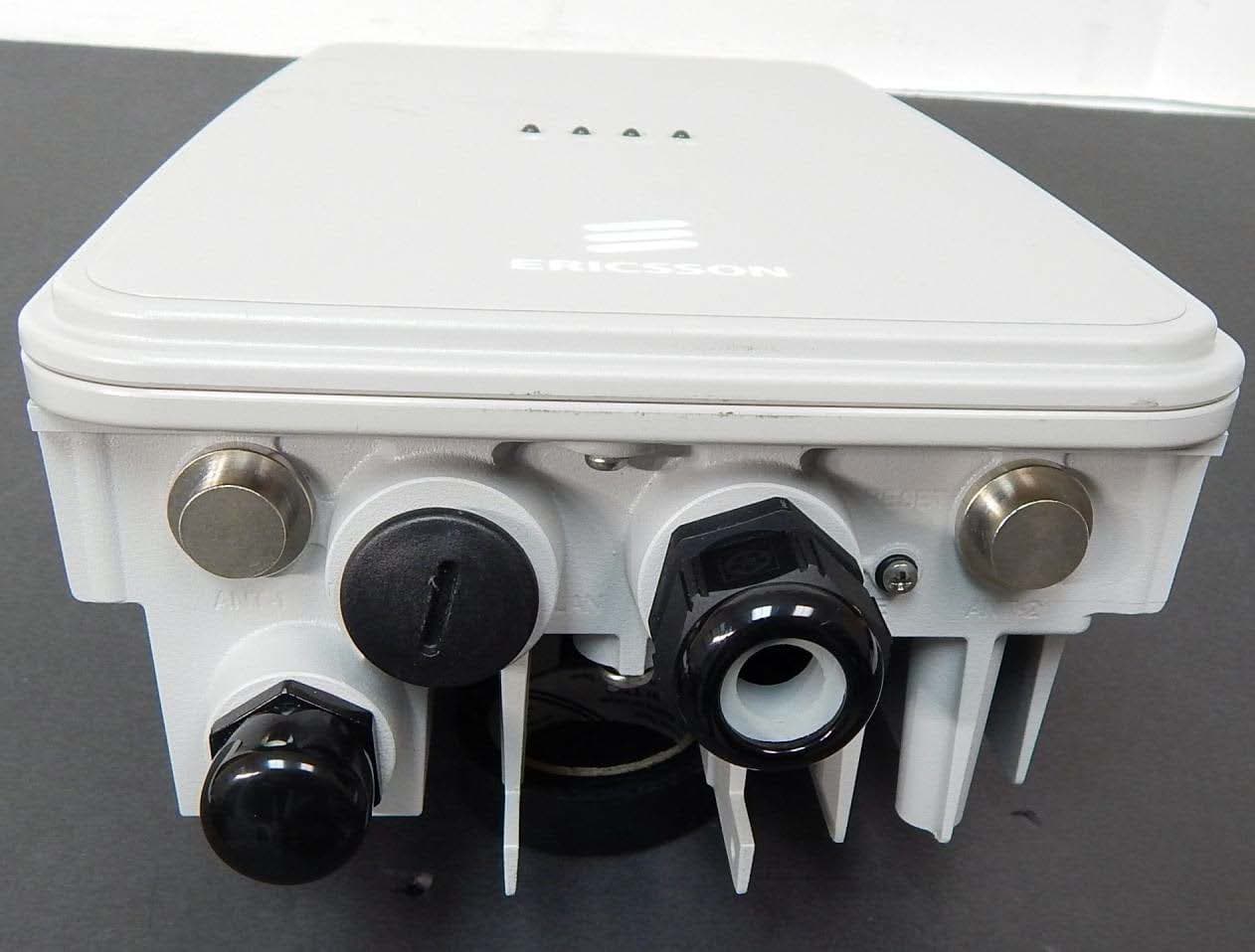
RAR80085008
Jul 02, 2014802.11n dual-band WIFI router
Equipment Class
NII - Unlicensed National Information Infrastructure TX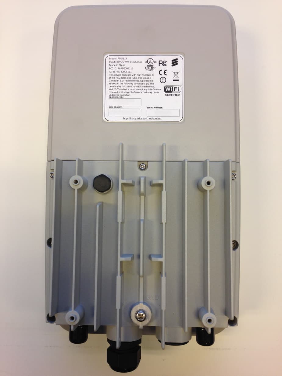
RAR80005111
Jul 02, 2014802.11n dual-band WIFI router
Equipment Class
DTS - Digital Transmission System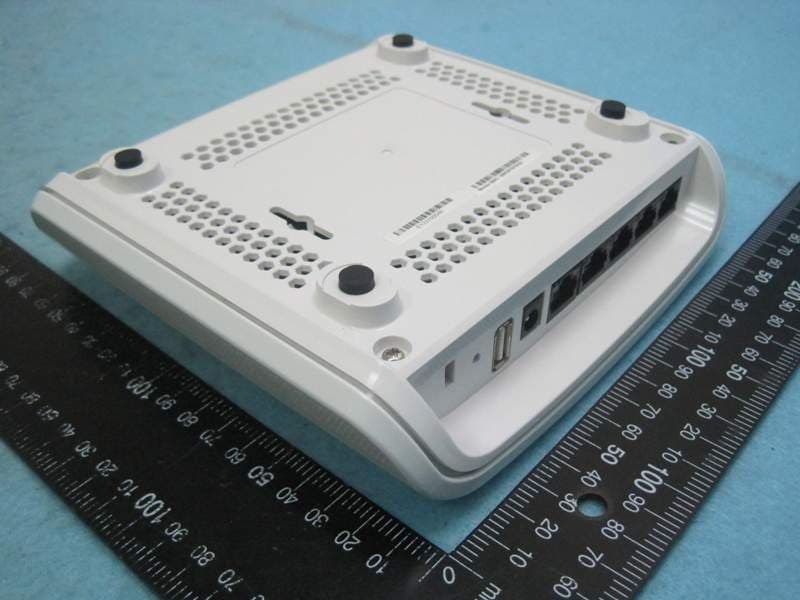
RAR40065006
Nov 30, 2013802.11AC Wireless Router
Equipment Class
NII - Unlicensed National Information Infrastructure TX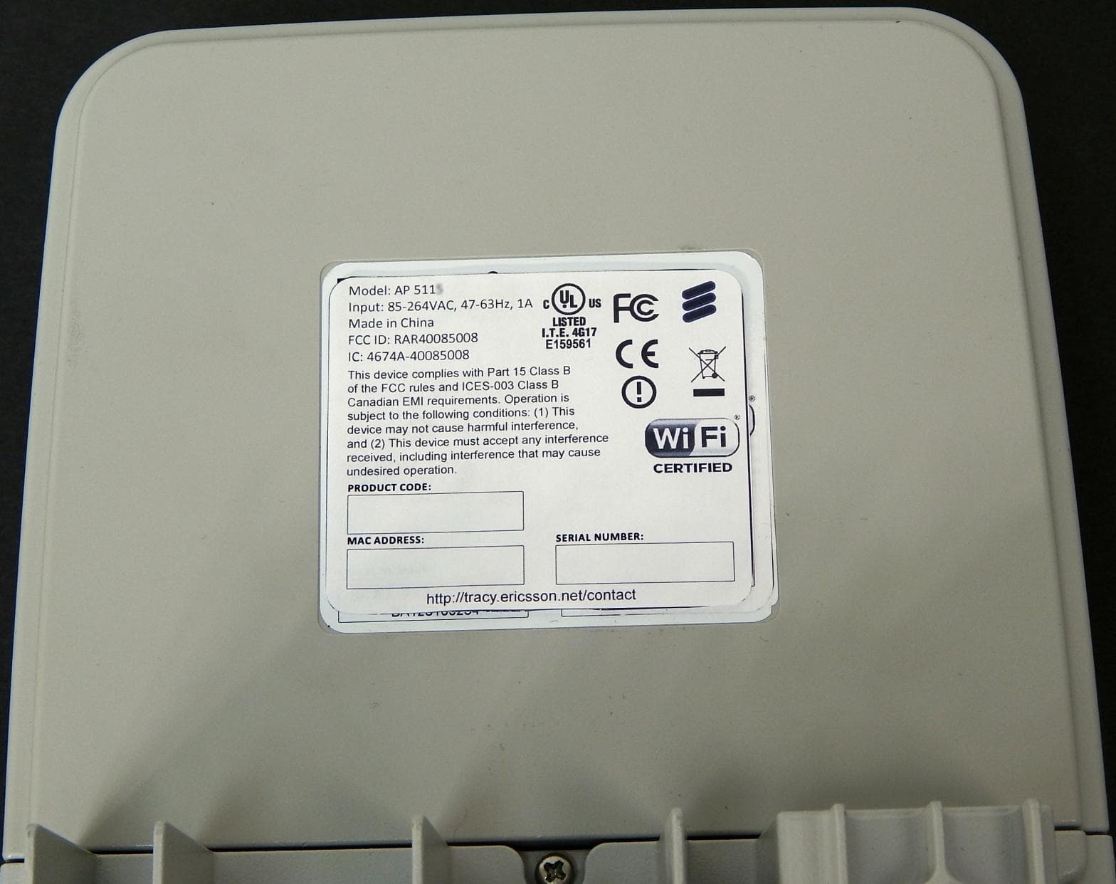
RAR40085008
Oct 28, 2013802.11n dual-band WIFI router
Equipment Class
DTS - Digital Transmission System