RAR200000032.4GHz WLAN Access Radio Module 3
Ericsson Wi-Fi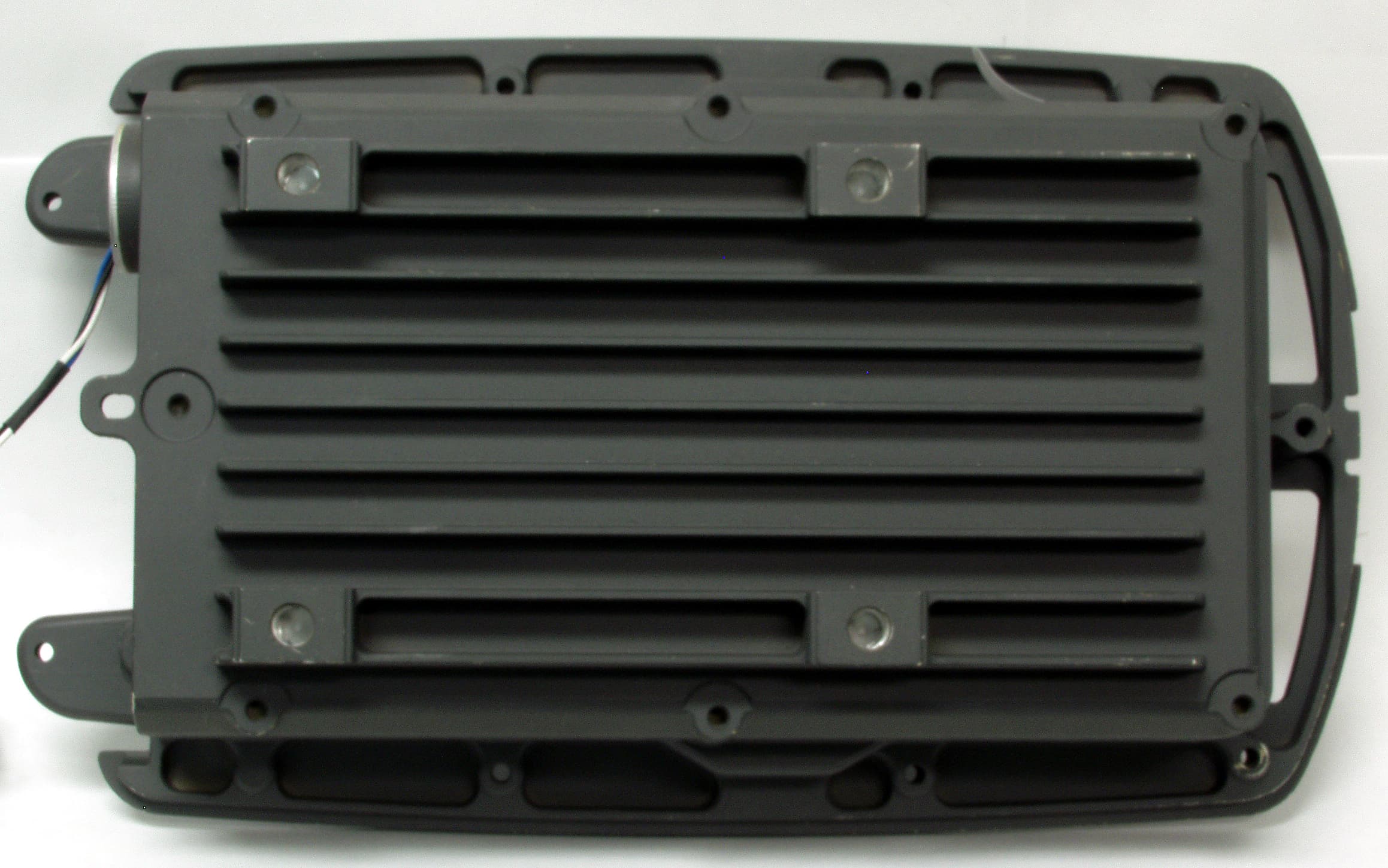
Click to zoom
Application Details
- Equipment Class
- DTS - Digital Transmission System
- Date of Grant
- Jul 14, 2005
- Application Purpose
- Original Equipment
- Date of Application
- Jul 14, 2005
- Equipment Note
- 2.4GHz WLAN Access Radio Module 3
- Frequency Range
- 2412.00000000 - 2462.00000000
- Company
- Ericsson Wi-Fi
- Country
- United States
Documents & Files
Document Text
Text extracted from the exhibit documents filed with the FCC. Open a document above to read the original.
Users Manual
Page 1 of 14 B2CC043AA B2CC043AA-A Product Manual 2.4 GHz WLAN Access Radio Module 3 Document Date: July 2005 Document Number: PM-B2CC043AA-A Document Version Number: 3 Document Status: Release © Copyright 2005 by BelAir Networks. All rights reserved.. B2CC043AA-A Product Manual – 2.4 GHz WLAN Radio Module June 2005 Page 2 of 14 PM-B2CC043AA-A Version 3 B2CC043AA-A Product Manual – 2.4 GHz WLAN Radio Module June 2005 Page 3 of 14 PM-B2CC043AA-A Version 3 Contents About this Document ....................................................................... 3 Introduction...................................................................................... 4 Conditions of Use ............................................................................. 5 Module Installation and Service..................................................... 7 Final Product Requirements........................................................... 8 Regulatory Statements .................................................................. 11 About this Document This document is a product manual for the B2CC043AA-A 2.4 GHz WLAN Access Radio Module 3, including its limitations on use in any product marketed or offered for sale. It is intended as a supplement to training and documentation by BelAir Networks Inc. or its authorized agents. B2CC043AA-A Product Manual – 2.4 GHz WLAN Radio Module June 2005 Page 4 of 14 PM-B2CC043AA-A Version 3 Introduction The B2CC043AA-A (hereafter referred to as “the module”) is a 2.4 GHz radio module compatible with the IEEE 802.11 standard for Wireless LAN operation. It is designed to be interoperable with WLAN products which are based on Direct Sequence Spread Spectrum (DSSS) radio technology. The module contains a complete 802.11b/g radio and Medium Access Control (MAC) protocol engine which allows implementation of an 802.11b/g access point (AP). The module is not intended for stand-alone operation. It will only be marketed as a complete product, in conjunction with a package, DC power supply and antenna (hereafter referred to as “the product” or the “final product”). Since the module has a BelAir networks proprietary digital interface, it cannot be directly connected to any standard telecommunications or computer devices. It can only be used with final products designed and authorized specifically for that purpose. B2CC043AA-A Product Manual – 2.4 GHz WLAN Radio Module June 2005 Page 5 of 14 PM-B2CC043AA-A Version 3 Conditions of Use General Conditions of Use This manual is intended to supplement training provided by BelAir Networks or authorized parties. The module B2CC043AA-A is only intended for use in BelAir Networks products and is not for sale to the general public as a stand- alone module. Please read this entire document, including the Regulatory Statements section before attempting to install or operate the module. Warning: Any use of B2CC043AA-A in any manner which is not expressly specified within this manual or specifically approved by BelAir Networks or its authorized agents will void the user’s right to operate this module, and is expressly forbidden by BelAir Networks. This includes any modification of the module, installation of the module in a configuration or used with an antenna which is not expressly listed in this document or approved by BelAir Networks. List of Approved Final Products The B2CC043AA-A module is only approved for use in the following BelAir Networks products: • BelAir200. See BelAir200 documentation for complete manufacturing instructions. • BelAir100. See BelAir100 documentation for complete manufacturing instructions. • BelAir50c. See BelAir50c documentation for complete manufacturing instructions. • Operation of the module within the products expressly listed above is required to ensure compliance to all FCC and Industry Canada regulations. Any modification of the module, or its use in any configuration not expressly listed above may void the user’s right to operate this module. B2CC043AA-A Product Manual – 2.4 GHz WLAN Radio Module June 2005 Page 6 of 14 PM-B2CC043AA-A Version 3 Country of Use B2CC043AA-A is certified with limited modular approval for use as an Intentional Radiator in the United States as device: FCC ID: RAR20000003 and in Canada as IC: 4674A-20000003. Please read all regulatory statements at the end of this document before any attempt to install or operate this module. The module is only certified for operation in the United States and Canada. Before attempting to install and operate this module in any other country, contact BelAir Networks for approval. Module Labeling One or more labels are applied to the module during manufacture, including a label which identifies the FCC and Industry Canada identification numbers. Do not attempt to remove any labels from the module. B2CC043AA-A Product Manual – 2.4 GHz WLAN Radio Module June 2005 Page 7 of 14 PM-B2CC043AA-A Version 3 Module Installation and Service Installation into a Product The module shall only be installed by a technician trained by BelAir Networks or its authorized agents. It should only be installed into an approved product (see above) following all manufacturing and service procedures for that product. The module should only be installed into a final product in a manufacturing or service depot site. Caution: B2CC043AA-A is an electro-static discharge (ESD) sensitive device. All appropriate ESD measures must be taken when handling the module. Failure to employ appropriate ESD protection may damage the module. Module Service The module is not intended as a field-serviceable unit. It contains no field- replaceable or field-serviceable parts, or any external adjustable mechanisms. The module should only be serviced in a manufacturing or service depot site approved by BelAir Networks or its authorized agents. B2CC043AA-A Product Manual – 2.4 GHz WLAN Radio Module June 2005 Page 8 of 14 PM-B2CC043AA-A Version 3 Final Product Requirements The requirements below apply to …
Text truncated - open the document above for the full version.
External Photos
6dBi Omni Antenna_MFB24006 6dBi Omni Antenna_MFB24006_02 8dBi Access Antenna BEL10012-A01_Front_01 8dBI Access Antenna BEL10012-A01_Front_02 8dBi Access Antenna BEL10012-A01_Rear_02 8dBi Omni Antenna_MFB24008 8dBi Omni Antenna_MFB24008_02 8dBi Omni Antenna_SPDG160 10dBi Omni Antenna_MFB24010 12 dBi Antenna_BelAir_Front 12dBi Antenna_BelAir_rear 12dBi Omni Antenna_MFB24012DT2 12dBi Omni Antenna_MFB24012DT2_02
RF Exposure Info
Prediction of MPE limit at a given distance 12 dBi Directional Antenna, BelAir B1BB032AA-A01 Equation from page 18 of OET Bulletin 65, Edition 97-01where: S = power density P = power input to the antennaG = power gain of the antenna in the direction of interest relative to an isotropic radiatorR = distance to the center of radiation of the antenna Maximum peak output power at antenna input terminal: 23.98 (dBm) Maximum peak output power at antenna input terminal: 250.0345362 (mW) Antenna gain(typical): 12 (dBi) Maximum antenna gain: 15.84893192 (numeric) Prediction distance: 25 (cm) Prediction frequency: 2437 (MHz) MPE limit for uncontrolled exposure at prediction frequency: 1 (mW/cm^2) Power density at prediction frequency: 0.504557 (mW/cm^2) Maximum allowable antenna gain: 14.97089881 (dBi) Margin of Compliance: 2.970898814 2 4 R PG S π = Prediction of MPE limit at a given distance 8 dBi Directional Antenna, BelAir BEL10012-A01 Equation from page 18 of OET Bulletin 65, Edition 97-01where: S = power density P = power input to the antennaG = power gain of the antenna in the direction of interest relative to an isotropic radiatorR = distance to the center of radiation of the antenna Maximum peak output power at antenna input terminal: 27.48 (dBm) Maximum peak output power at antenna input terminal: 559.7576015 (mW) Antenna gain(typical): 8 (dBi) Maximum antenna gain: 6.309573445 (numeric) Prediction distance: 25 (cm) Prediction frequency: 2437 (MHz) MPE limit for uncontrolled exposure at prediction frequency: 1 (mW/cm^2) Power density at prediction frequency: 0.449687 (mW/cm^2) Maximum allowable antenna gain: 11.47089881 (dBi) Margin of Compliance: 3.470898814 2 4 R PG S π = Prediction of MPE limit at a given distance 12 dBi Omnidirectional Antenna, MFB24012DT2 Equation from page 18 of OET Bulletin 65, Edition 97-01where: S = power density P = power input to the antennaG = power gain of the antenna in the direction of interest relative to an isotropic radiatorR = distance to the center of radiation of the antenna Maximum peak output power at antenna input terminal: 23.98 (dBm) Maximum peak output power at antenna input terminal: 250.0345362 (mW) Antenna gain(typical): 12 (dBi) Maximum antenna gain: 15.84893192 (numeric) Prediction distance: 25 (cm) Prediction frequency: 2437 (MHz) MPE limit for uncontrolled exposure at prediction frequency: 1 (mW/cm^2) Power density at prediction frequency: 0.504557 (mW/cm^2) Maximum allowable antenna gain: 14.97089881 (dBi) Margin of Compliance: 2.970898814 2 4 R PG S π = Prediction of MPE limit at a given distance 10 dBi Omnidirectional Antenna, MFB24010 Equation from page 18 of OET Bulletin 65, Edition 97-01where: S = power density P = power input to the antennaG = power gain of the antenna in the direction of interest relative to an isotropic radiatorR = distance to the center of radiation of the antenna Maximum peak output power at antenna input terminal: 26.00 (dBm) Maximum peak output power at antenna input terminal: 398.1071706 (mW) Antenna gain(typical): 10 (dBi) Maximum antenna gain: 10 (numeric) Prediction distance: 25 (cm) Prediction frequency: 2437 (MHz) MPE limit for uncontrolled exposure at prediction frequency: 1 (mW/cm^2) Power density at prediction frequency: 0.506886 (mW/cm^2) Maximum allowable antenna gain: 12.95089881 (dBi) Margin of Compliance: 2.950898814 2 4 R PG S π = Prediction of MPE limit at a given distance 8 dBi Omnidirectional Antenna, MFB24008 Equation from page 18 of OET Bulletin 65, Edition 97-01where: S = power density P = power input to the antennaG = power gain of the antenna in the direction of interest relative to an isotropic radiatorR = distance to the center of radiation of the antenna Maximum peak output power at antenna input terminal: 27.48 (dBm) Maximum peak output power at antenna input terminal: 559.7576015 (mW) Antenna gain(typical): 8 (dBi) Maximum antenna gain: 6.309573445 (numeric) Prediction distance: 25 (cm) Prediction frequency: 2437 (MHz) MPE limit for uncontrolled exposure at prediction frequency: 1 (mW/cm^2) Power density at prediction frequency: 0.449687 (mW/cm^2) Maximum allowable antenna gain: 11.47089881 (dBi) Margin of Compliance: 3.470898814 2 4 R PG S π = Prediction of MPE limit at a given distance 6 dBi Omnidirectional Antenna, MFB24006 Equation from page 18 of OET Bulletin 65, Edition 97-01where: S = power density P = power input to the antennaG = power gain of the antenna in the direction of interest relative to an isotropic radiatorR = distance to the center of radiation of the antenna Maximum peak output power at antenna input terminal: 27.48 (dBm) Maximum peak output power at antenna input terminal: 559.7576015 (mW) Antenna gain(typical): 6 (dBi) Maximum antenna gain: 3.981071706 (numeric) Prediction distance: 25 (cm) Prediction frequency: 2437 (MHz) MPE limit for uncontrolled exposure at prediction frequency: 1 (mW/cm^2) Power density at prediction frequency: 0.283733 (mW/cm^2) Maximum allowable antenna gain: 11.47089881 (dBi) Margin of Compliance: 5.470898814 2 4 R PG S π = Prediction of MPE limit at a given distance 8 dBi Omnidirectional Antenna, SPDG160 Equation from page 18 of OET Bulletin 65, Edition 97-01where: S = power density P = power input to the antennaG = power gain of the antenna in the direction of interest relative to an isotropic radiatorR = distance to the center of radiation of the antenna Maximum peak output power at antenna input terminal: 27.48 (dBm) Maximum peak output power at antenna input terminal: 559.7576015 (mW) Antenna gain(typical): 8 (dBi) Maximum antenna gain: 6.309573445 (numeric) Prediction distance: 25 (cm) Prediction frequency: 2437 (MHz) MPE limit for uncontrolled exposure at prediction frequency: 1 (mW/cm^2) Power density at prediction frequency: 0.449687 (mW/cm^2) Maximum allowable antenna gain: 11.47089881 (dBi) Margin of Compliance: 3.470898814 2 4 R PG S π =
RF Exposure Info
BelAir Networks 2.4 GHz Radio Module MPE Engineering Analysis June 30, 2005 Engineering Analysis MPE for 2.4 GHz Transceiver FCC ID: RAR20000003 BelAir Networks This analysis was performed as part of the FCC certification requirements for spread spectrum devices, according to the requirements of: FCC part 15.247 (b) (4), and FCC OET Bulletin 65 “Evaluating Compliance with FCC Guidelines for Human Exposure to Radio frequency Electromagnetic Fields”. • Module RAR20000003 will be mounted in BelAir Networks host units and will be professionally installed (Fixed) to provide a minimum separation distance of 25.1 cm (10 inches) from all persons as detailed in co-location compliance table below. • The device will not be co-located or operated in conjunction with any other antenna or transmitter not described in this table and application. • This device will only be operated according to the exposure conditions described in this application. • End users and installers will be provided with antenna installation and transmitter operating conditions for satisfying RF exposure compliance. The measured worst case transmit power yielding the worst case EIRP were used for the MPE calculations. Calculations were performed based on FCC OET Bulletin 65. The calculations are performed based on the following formula provided in OET 65: S = EIRP / (4πR 2 ). Co-location compliance for multiple frequency exposure criteria to the power density exposure limit is detailed in the table below: Total Density for co-located radios [mW/cm2] Worst Case Total EIRP [dBm] Max Power Density [mW/cm2] Worst Case Total EIRP [dBm] Max Power Density [mW/cm2] Worst Case Total EIRP [dBm] Max Power Density [mW/cm2] Worst Case Total EIRP [dBm] Max Power Density [mW/cm2] [mW/cm2] Limit [mW/cm2] 35.000.40 29.000.1029.000.1029.000.10 0.701complies 35.000.40 32.000.2032.000.2032.000.20 1.001complies 35.000.40 29.000.1029.000.1029.000.10 0.701complies RAR 20001002RAR 20001002RAR 20001002 RAR 20005001RAR 20005001RAR 20005001 RAR 20001001RAR 20001001RAR 20001001 802.11a Radio RARxxxxxxx 802.11 b/g Radio RAR20000003 Co-location Compliance for Integrated 802.11b/g & 802.11a Radios at 25.1 cm BelAir Networks 2.4 GHz Radio Module MPE Engineering Analysis June 30, 2005 This calculation is a worst-case analysis since it assumes the device is continuously transmitting. The device utilizes the 802.11 WLAN protocol which operates in time- division duplex (TDD) mode, so the transmit duty cycle can never be 100% in normal operation. It is also assumed that the antennas are transmitting in the same direction. Based on these calculations and using the limit for general population/uncontrolled environment of 1.0 mW/cm 2 at 2.4 GHz, the BelAir Networks units meets MPE requirements set forth in documents above, with a minimum safety distance between antenna and operator of 25.1 cm (10 inches). Products which contain module RAR20000003 (B2CC043AA-A) shall only be installed by professional installers trained by BelAir Networks or its authorized agents. In addition to normal installation procedures and good installation practice, professional installers are responsible to ensure that: 1. Only an approved antenna (see Product Manual) is connected to the module, and, 2. The antenna is mounted in such a manner and in such a location that access to the antenna by the general population is minimized. Access to the antenna by the general population is limited to greater than 25.1 cm (10 inches) during normal operation. The equipment therefore fulfills the requirements on power density for general population/uncontrolled exposure and therefore complies with the requirements of FCC Part 15.247 (b) (4) and FCC Bulletin 65.
Test Report
FCC Part 15 Subpart C, 15.247 : February 2005 Test Report: 5W43708 Issue 2 Applicant: BelAir Networks Inc., 603 March Road, Ottawa, ON, K2K 2M5 Apparatus: B2CC043AA Wireless LAN Access Radio Module 3 (ARM3) 2.4 GHz Band FCC ID: RAR 20000003 In Accordance With: FCC Part 15 Subpart C, 15.247 FHSS System and Digitally Modulated Radiators 902-928MHz, 2400 - 2483.5 MHz, 5725-5850MHz Tested By: Nemko Canada Inc. 303 River Road Ottawa, Ontario K1V 1H2 Authorized By: Sim Jagpal, Resource Manager Date: 6 July 2005 Total Number of Pages: 118 Nemko Canada Inc. REPORT SUMMARY Report Number: 5W43708 Issue 2 FCC ID: RAR 20000003 Specification: FCC Part 15 Subpart C, 15.247 Page 2 of 118 Report Summary These tests were conducted on a sample of the equipment for the purpose of demonstrating compliance with Part 15, Subpart C. Radiated tests were conducted is accordance with ANSI C63.4-2003. Radiated emissions are made on an open area test site. A description of the test facility is on file with the FCC. The assessment summary is as follows: Apparatus Assessed: B2CC043AA Wireless LAN Access Radio Module 3 (ARM3) 2.4 GHz Band Specification: FCC Part 15 Subpart C, 15.247 Compliance Status: Complies Exclusions: None Non-compliances: None Report Release History: Original Release Author: Roman Kuleba Note that the results contained in this report relate only to the items tested and were obtained in the period between the date of initial receipt of samples and the date of issue of the report. This test report has been completed in accordance with the requirements of ISO/IEC 17025. Nemko Canada Inc. authorizes the applicant to reproduce this report provided it is reproduced in its entirety and for use by the company’s employees only. Any use which a third party makes of this report, or any reliance on or decisions to be made based on it, are the responsibility of such third parties. Nemko Canada Inc. accepts no responsibility for damages, if any, suffered by any third party as a result of decisions made or actions based on this report. Nemko Canada Inc. REPORT SUMMARY Report Number: 5W43708 Issue 2 FCC ID: RAR 20000003 Specification: FCC Part 15 Subpart C, 15.247 Page 3 of 118 TABLE OF CONTENTS Report Summary......................................................................................................................................... 2 Section 1 : Equipment Under Test............................................................................................................. 4 1.1 Product Identification .................................................................................................................................4 1.2 Samples Submitted for Assessment............................................................................................................4 1.3 Theory of Operation ...................................................................................................................................5 1.4 Technical Specifications of the EUT ..........................................................................................................7 Section 2 : Test Conditions......................................................................................................................... 8 2.1 Specifications .............................................................................................................................................8 2.2 Deviations From Laboratory Test Procedures ............................................................................................8 2.3 Test Environment .......................................................................................................................................8 2.4 Test Equipment...........................................................................................................................................8 Section 3 : Observations ............................................................................................................................. 9 3.1 Modifications Performed During Assessment ............................................................................................9 3.2 Record Of Technical Judgements ...............................................................................................................9 3.3 EUT Parameters Affecting Compliance .....................................................................................................9 3.4 Test Deleted................................................................................................................................................9 Section 4 : Results Summary ................................................................................................................... 10 4.1 FCC Part 15 Subpart C : Test Results ......................................................................................................11 Appendix A : Test Results ........................................................................................................................ 12 Power Line Conducted Emissions ...................................................................................................................12 Radiated Emissions within Restricted Bands ..................................................................................................17 Radiated Emissions within Restricted Bands - Band Edge..............................................................................20 Occupied Bandwidth .......................................................................................................................................76 Maximum Peak Output Power.........................................................................................................................89 Supply Voltage Variation ................................................................................................................................98 Emissions Not in Restricted Bands…
Text truncated - open the document above for the full version.
Test Setup Photos
Conducted Disturbance at Mains, Setup Photos Conducted Emissions Setup: Spurious Emissions Setup:
Contact Information
Applicant
Roland Andrew Smith(R&D Wi-Fi Products)
Technical Contact
Non-Technical Contact
BelAir Networks IncStephen Rayment
[email protected]613 254 7070
Test Firm
Nemko Canada Inc. (Ottawa)Charles Neal
Technical Specifications
| # | Rule Parts | Frequency Range | Power Output |
|---|---|---|---|
| 1 | 15C | 2.41 GHz - 2.46 GHz | 500.00 mW |
Other Applications from Ericsson Wi-Fi
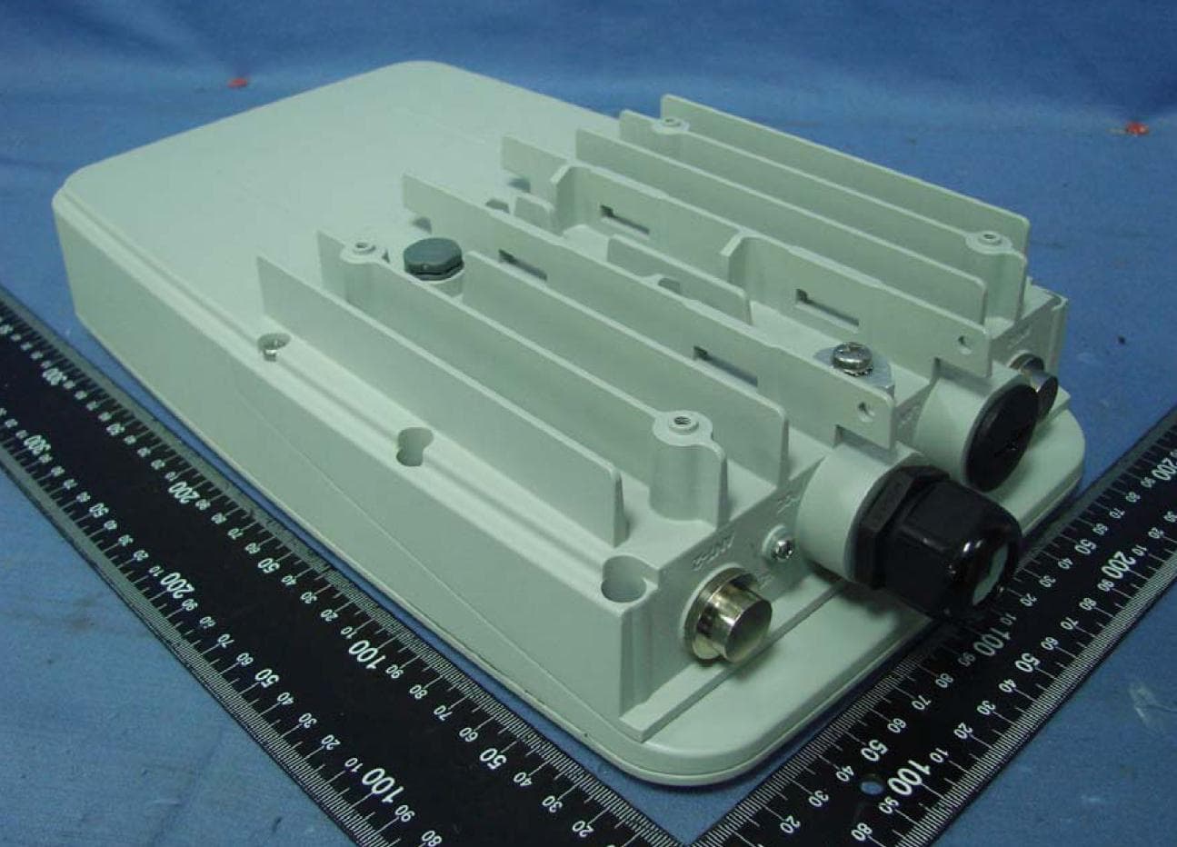
RAR80005000
Jul 07, 2014802.11n dual-band WIFI router
Equipment Class
NII - Unlicensed National Information Infrastructure TX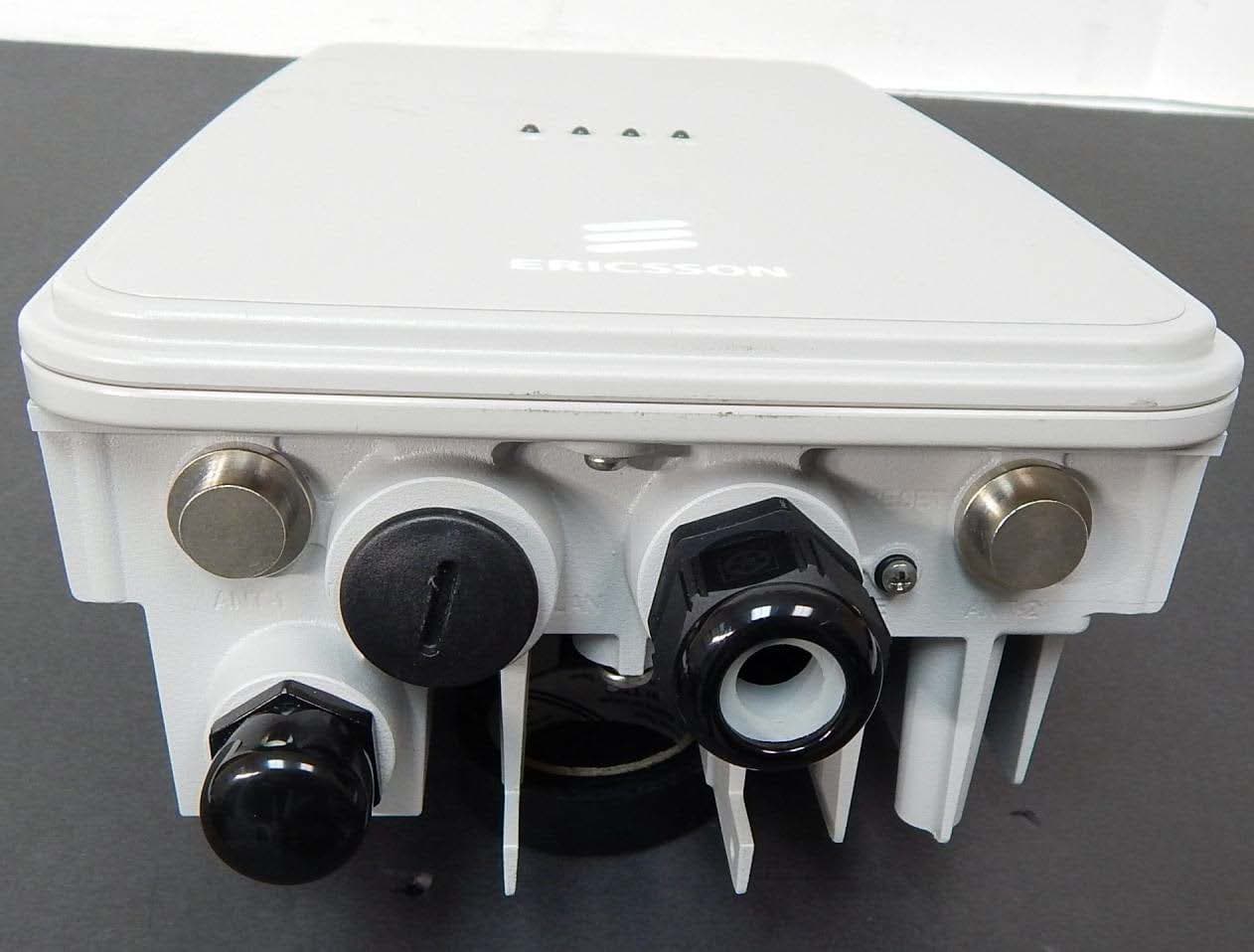
RAR80085008
Jul 02, 2014802.11n dual-band WIFI router
Equipment Class
NII - Unlicensed National Information Infrastructure TX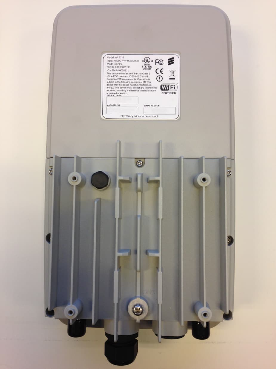
RAR80005111
Jul 02, 2014802.11n dual-band WIFI router
Equipment Class
DTS - Digital Transmission System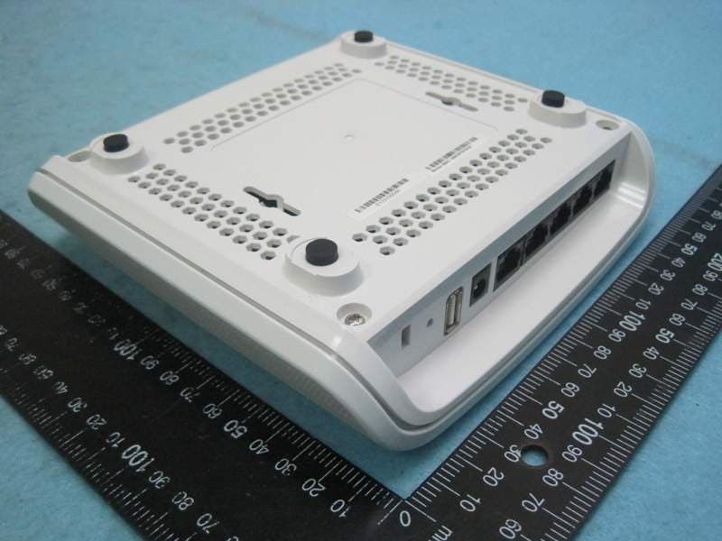
RAR40065006
Nov 30, 2013802.11AC Wireless Router
Equipment Class
NII - Unlicensed National Information Infrastructure TX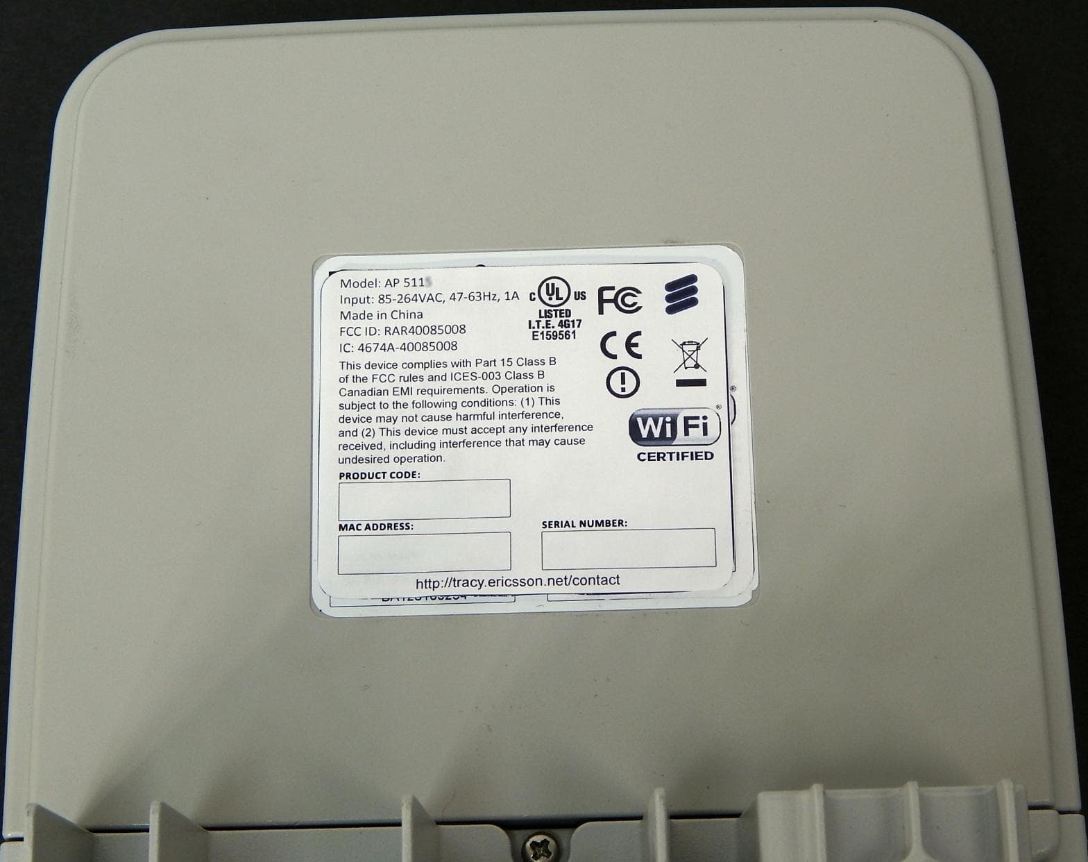
RAR40085008
Oct 28, 2013802.11n dual-band WIFI router
Equipment Class
DTS - Digital Transmission System