RB2AGM1100PCS Mobile Phone
Franklin Wireless Corp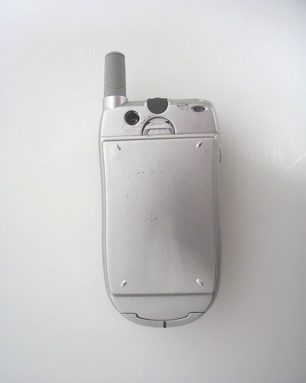
Click to zoom
Application Details
- Equipment Class
- PCE - PCS Licensed Transmitter held to ear
- Date of Grant
- Jul 31, 2003
- Application Purpose
- Original Equipment
- Date of Application
- Jul 31, 2003
- Equipment Note
- PCS Mobile Phone
- Frequency Range
- 1850.20000000 - 1909.80000000
- Company
- Franklin Wireless Corp
- Country
- United States
Documents & Files
Document Text
Text extracted from the exhibit documents filed with the FCC. Open a document above to read the original.
Users Manual
USER’S MANUAL Menu Your phone has a wide range of functions that is grouped in menus and submenus. Users can access these functions by navigation key and selection keys. Menu Tree 1 Call Records 1 Missed calls 1 Call 2 Store 3 Erase 2 Received Calls 1 Call 2 Store 3 Erase 3 Dialed Calls 1 Call 2 Store 3 Erase 4 Call Timers 1 Last Call Timer 2 Total Received Calls 3 Total Dialed Calls 4 Total Calls 5 Reset All Timers 2 Messages 1 Read Messages 1 Inbox 1 Edit 2 Send 3 Erase 2 Outbox 1 Read 2 Write Messages 1 Only Send 2 Only Save 3 Voice Mail 1 Voice Mail Number 2 Dial to VM Server 4 Message Setup 1 Text Message 1 Service Center 2 Message Type 1 Text 2 Fax 3 Email 3 Message Expiry 1 1 hour 2 6 hours 3 12 hours 4 24 hours 5 72 hours 6 1 Week 7 Maximum 2 Public Setup 1 Reply Path 1 Enable 2 Disable 2 Status Path 1 Enable 2 Disable 5 Broadcast Message 1 Read 2 Setup 3 Channel 4 Language 3 Ring Melody 1 Ring Mode 1 Melody 2 Vibrate then Melody 3 Vibrate 4 Light 2 Ringer 1 Volume Volume 0~5 2 Type Melody 1~20 3 Keypad Tone 1 Tone 2 Beep 3 Off 4 Message Alert 1 On 2 Off 5 Minute Minder 1 On 2 Off 6 Download Melodies 5 Extras 1 Calculator 2 World Time 3 Alarm 1 Time 2 Enable/Disable 3 Alarm Type 4 Game 1 Slot Machine 2 Draw Poker 3 Black Jack 5 Cyber Health 1 Bio Rhythm 2 Fatness 3 Pink Schedule 4 Calories 6 Network Features 1 Call Divert 1 Divert Always 2 On Busy 3 No Reply 4 Unreachable 5 Cancel all 2 Call Barring 1 All Outgoing Calls 2 All International Calls 3 International Except to home 4 All Incoming Calls 5 Incoming (Roam) 1 Interrogate 2 Activate 3 Deactivate 6 Cancel All 7 Change Password 3 Call Waiting 1 Check Settings 2 Activate 3 Deactivate 4 Net Selection Mode 1 Automatic Selection 2 Manual Selection 7 Settings 1 Display 1 Animations 1 Power On Screen 2 Idle Screen 3 Power Off Screen 2 Backlight 1 Short 2 Long 3 Off 3 LCD Contrast 0 – 100 (in increments of 5) 4 SW Version 2 Language 1 English 2 Spanish 3 Simplified Chinese 3 Call Settings 1 Any Key Answer 1 On 2 Off 2 Auto Redial 1 On 2 Off 3 Flip Answer Mode 1 On 2 Off 4 Caller ID 1 Send 2 Hide 4 Security Settings 1 Phone Lock 1 Enable 2 Disable 3 Change Password 2 PIN Check 1 Enable 2 Disable 3 Change PIN1 3 SIM Lock 1 Enable 2 Disable 3 Change Password 4 FDN Mode 1 Enable 2 Disable 5 Change PIN2 5 Time/Date Date Time Place 12Hour or 24 Hour 6 Select Band 1 Select EGSM/DCS 2 Select PCS 7 Default Settings Enter Password 8 Data Service 1 Internet Access 2 Data Service 1 Enable Data 2 Disable Data 3 Check Data Status 9 Phonebook 1 Search 1 SIM 2 ME 2 Add 1 SIM 2 ME 3 Delete All 1 SIM 2 ME 4 Storage Status 1 SIM: Total Used Free 2 ME: Total Used Free 5 Own Number 1 Display 2 Edit Call record Call Record This network feature automatically keeps track of numbers dialed and received, and the time you’ve spent in those calls. -Missed Calls -Received Calls -Dialed Calls -Call Timers Last Call Timer Total Received Calls Total Dialed Calls Total Calls Reset All Timers Missed Calls List of phone calls you did not answer 1 Choose Call Record and press Select 2 Highlight Missed Calls and press Select 3 Scroll through the missed calls and Press Select to view the details 4 Press Menu for three options • Call – Call the number user has chosen • Store – Store the phone number user has chosen • Erase – Erase the phone number user has chosen 5 Press Cancel to go back to the previous screen, -OR- Press End to go back to Main Screen Received Calls List of phone numbers you answered 1 Choose Call Record and press Select 2 Highlight Received Calls and press Select 3 Scroll through the Received Calls and Press Read to view the details 4 press Menu for three options • Call – Call back the number user has chosen • Store – Store the phone number user has chosen • Erase – Erase the phone number user has chosen 5 Press Cancel to go back screen back, -OR- Press End to go back to Main Screen Dialed Calls List of phone numbers you dialed 1 Choose Call Record and press Select 2 Highlight Dialed Calls and press Select 3 Scroll through the Dialed Calls and Press Read to view the details 4 press Menu for three options • Call – Call back the number user has chosen • Store – Store the phone number user has chosen • Erase – Erase the phone number user has chosen 5 Press Cancel to go back screen back, -OR- Press End to go back to Main Screen Call Timers Viewing and resetting all the call timers Last Call Time Time spend on last call 1 Choose Call Record and press Select 2 Highlight Call Timers and press Select 3 Choose Last Call time and press Select to view the status 4 Press Reset to reset timer -OR- Press Back to exit without resetting Total Received Calls Total time spend on received calls 1 Choose Call Record and press Select 2 Highlight Call Timers and press Select 3 Choose Total Received Calls and press Select to view the status 4 Press Reset to reset timer -OR- Press Back to exit without resetting Total Dialed Calls Total dialed time spend on dialed calls 1 Choose Call Record and press Select 2 Highlight Call Timer and press Select 3 Choose Total Dialed Calls and press Select to view the status 4 Press Reset to reset timer -OR- Press Back to exit without resetting Total Calls Total time spend on incoming and out going calls 1 Choose Call Record and press Select 2 Highlight Call Timer and press Select 3 Choose Total Calls and press Select to view the status 4 Press Reset to reset timer -OR- Press Back to exit without resetting Reset All Timer Resetting all timers 1 Choose Call Record and press Select 2 Highlight Call Timer and press Select 3 Choose Reset All Timer and press Select 4When Reset All Timers? Press Select to reset timer -OR- Press Cancel to exit without resetting Message The message service allow users to send short text messages to the device that can receive short text messages, such as other phones, computers, fax machines, and pagers. -Read Messages Inbox Outbox -Write Messages -Voicemail Voice Mail Number Dial to VM Server - Message Setup Text Me…
Text truncated - open the document above for the full version.
Cover Letter(s)
From: Thu Chan Sent: Wednesday, July 30, 2003 2:41 PM To: Steve Cheng Cc: Scott Klackle; Mike Kuo; Claire Hoque Subject: RE: RE: AN03T3107, Accetio, RB2AGM1100 Hi Steve, Please see answers below with revised report attachment. Thanks & Regards, Thu RT for project: AN03T3107 Notice_content Question #1: 2_SAR Tset Plots.pdf exceed 4M bytes. _ [Thu Chan] pls see revised SAR Test Plots as attached. Question #2: P43 of users manual stated that “Vehicle Mounted External Antenna (optional, if available.) A minimum separation distance of 7.9 inches (20cm) must be maintained between the user/bystander requirements. And the vehicle mounted external antenna to satisfy FCC RF exposure. For more information about RF exposure, please visit the FCC website at www.fcc.gov”. But MPE calculation shown that for a 30dBm output power there is a tendency that an external antenna with a gain great than 7dBi could potentially exceed the MPE limit at 20cm. Please clarifies how user could avoid this situation to happen. _ [Thu Chan] Info has been removed from the users manual. pls see revised user's manual. Question #3: Setup photos reported only the Radiated Emission setup. Please update setup photos to include all related tests. _ [Thu Chan] Setup photo had been updated. pls see revised user's manual. Question #4: P10 of EMC report, please explain why maximum happen at Horizontal when ant is Vertical? _ [Thu Chan] The pictures inserted error, actually the worst postion should be at horizontal position. Please refer to revised report. Question #5: P10 of EMC report, EIRP calculation for Low and Middle channel are 0.1 dB off. Please re-check calculation. For example a middle channel 23.5-1.4+7.7=29.8 but table shown 19.9 dB. _ [Thu Chan] The values were rounding off during the calculation. Question #6: EUT setup photo is not matching the EUT? Please explain. _ [Thu Chan] The pictures inserted error. Please refer to revised report. Question #7: P22, please explain why 41.6dB offset was used on conducted emission measurement. _ [Thu Chan] Becasse the 40dB coupler & cables are used during the measurement. For your info: this phone equipped with two bands EGSM / DCS and PCS, but only PCS could be used in US territory. The items indicated above must be submitted before processing can continue on the above referenced application. Failure to provide the requested information within 60 days of the original e-mail date may result in application dismissal and forfeiture of the filing fee. Also, please note that partial responses increase processing time and should not be submitted. Any questions about the content of this correspondence should be directed to the e-mail address listed below the name of the sender. Best Regards Steve Cheng Compliance Certification Services 561F Monterey Road Morgan Hill, CA 95037 Tel:(408)463-0885 x:119 Fax:(408)463-0888 [email protected] http:\\www.ccsemc.com
ID Label/Location Info
PROPOSED FCC ID LABEL AND LOCATION ACCETIO, INC. This device complies with Part 24 of the FCC Rules. FCC ID: RB2AGM1100 FCC ID LABEL LOCATION
Parts List/Tune Up Info
4. Calibration Procedure 4.1. Calibration Setup Procedure ¾ Install calibration software on PC ¾ Install GPIB card in PC and connect it to GPIB port on GSM Test Set such as HP8922, HP8960, CMD55, CMU200, W4400, and etc. ¾ Connect serial cable to computer’s com port and system connector (including the serial port line) to the unit under test ¾ Connect RF cable from the test port (RF switch) on the unit under test to GSM Test Set ¾ To get into calibration mode, loop-back the signal DEBUG_TX and DEBUG_RX before turning on the unit under test Accetio Confidential Proprietary 32 4.2. Calibration Items CCXO Characterization ¾ Function Diagram ¾ Procedure 9 Handset receives signal of known frequency Channel 62 with -40dBm 9 Get the coarse adjustment register by changing the register seeting until the frequency error reach 0 9 Ccontrol DAC stepped, frequency error scan taken by DSP each step, and then DAC setting/frequency error table derived. Finally generate polynomial from table 9 Load coefficient of polynomial and output capacitance register value to DSP Receiver Gain Stage Calibration ¾ Function Diagram Accetio Confidential Proprietary 33 Accetio Confidential Proprietary 34 ¾ Procedure 9 Handset receives signal of known frequency Channel 62/698 with -40dBm 9 Each gain stage individually enabled IAIC Section in U200 All IAIC is set to 0 RF Section in U100 LNA Gain Mixer Gain LPF Gain VGA1 Gain VGA2 Gain 9 Resultant gain calculated Gain Code Gain 0x0000 G0 = Pref(-33) 0xA000 G1 = Gm in 0x8000 G2 = Gm in +G V 2 1 0x6000 G3 = Gm in +G V 2 2 0x4000 G4 = Gm in +G V V 2 1 +G V 2 2 0x4008 G5 = Gm in + G V 2 1 +GV 2 2 + GV 13 0x5000 G6 = Gm in + G V 2 1 +GV 2 2 + GL P F 0x4400 G7 = Gm in + G V 2 1 +GV 2 2 + GL N A 0x4408 G8 = Gm in + G V 2 1 +GV 2 2 + GL N A + G V 1 3 0x5400 G9 = Gm in + G V 2 1 +GV 2 2 + GL P F + GL N A 0x4C00 G1 0 = Gm in + G V 2 1 +GV 2 2 + G M IX + GL N A 0x4C08 G1 1 = Gm in + G V 2 1 +GV 2 2 + G M IX + GL N A +G V 1 3 0x5C00 G1 2 = Gm in + G V 2 1 +GV 2 2 ++GL P F + GM IX + GL N A 0x5C08 G1 3 = Gm in +G V 2 1+ GV2 2 ++GL PF+ GM IX + GL N A +G V 1 3 0x5C04 G1 4 = Gm in + G V 2 1 +GV 2 2 ++GL P F + GM IX + GL N A +GV1 2 0x5C0C G1 5 = Gm in + G V 2 1 +GV 2 2 ++GL P F + GM IX + GL N A +GV1 2 + GV 1 3 0x5C02 G1 6 = Gm in + G V 2 1 +GV 2 2 ++GL P F + GM IX + GL N A +GV1 1 9 Data transferred into NV storage as AGC data table 9 Carried out 900MHz EGSM, DCS1800MHz and then PCS 1900MHz Transmit IQ Gain & Phase Balance Calibration ¾ Function Diagram TXI+ TXI- TXQ+ TXQ- I Channel TX GMSK Modulator DAC Burst Store Q Channel TX DAC ¾ Procedure 9 Handset transmits to spectrum analyzer of GSM Test Set 9 Determine optimal values for IAIC register (Gain and Phase Imbalance should be calibrated respectively) Measure amplitude of side bands at 3 different register settings (+3, 0, -3) Perform line fit on data TXI, TXQ, Gain Imbalance 9 Optimal values minimize the side bands 9 Sideband attenuation relative to negative sideband is measured after optimization. The attenuation of unwanted signals must be min. of 40dB Transmit IQ DC Offset Calibration ¾ Procedure 9 Handset transmits to spectrum analyzer of GSM Test Set 9 Determine optimal values for IAIC register (I and Q should be calibrated respectively) Measure amplitude of side bands at 3 different register settings (+16, 0, -16) Perform line fit on data TXI, TXQ, DC Offset 9 Optimal values minimize the side bands 9 Carrier attenuation relative to negative sideband is measured after optimization. The attenuation of unwanted signals must be min. of 40dB Accetio Confidential Proprietary 35 Transmit Power Calibration ¾ Function Diagram ¾ Ramp Profile 9 Ramp profile consist 18 Scaling Factors and Duration, 9 for ramp up and 9 for Ramp Down. 9 Ramp Step Value: Ramp(nth)=a(nth)*(Final- Pedestal)+Pedestal Duration =(n+1)nits (1nit=Frame/10000=0.4615us ) 9 The scaling factor and duration are same for all the band and power levels 9 Final Value is different and should be calibrated for each power level 9 Pedestal is same for each band and only need calibrated once in each band Accetio Confidential Proprietary 36 Battery Voltage Calibration ¾ Procedure 9 Set the PS to 3.1V and get the 1 st ADC reading 9 Set the PS to 4.2V and get the 2 nd ADC reading 9 Calculate K and b and save them to NVM Battery Pack Size Calibration ¾ Procedure 9 Set V POWER to 5.0V and connect an known value resistance R PACK =10K in the terminal BAT_PK_IN and then measure V MUX and calculate B = (V POWER /V MUX -1) 9 Save B to the NVM Charging Current Calibration ¾ Procedure 9 Connect 5V PS to charger terminal and set the DAC value to 225 9 Connect the 7Ohms resistance between V BATTERY terminal produce 0.1C current, then get the ADC reading 9 Connect the 70Ohms resistance between V BATTERY terminal produce 1C current, then get the ADC reading 9 Calculate M and e and save them to NVM Accetio Confidential Proprietary 37
RF Exposure Info
in accordance with the requirements of FCC Report and Order: ET Docket 93-62, and OET Bulletin 65 Supplement C for Tri-Bands (GSM/DCS/PCS) Cellular Phone MODEL: AGM1100 FCC ID: RB2AGM1100 July 17, 2003 REPORT NO: 03U2057-1 Prepared for Accetio, Inc. 9565 Waples St., Suite 250 San Diego, CA 92121 USA Prepared by COMPLIANCE CERTIFICATION SERVICES 561F MONTEREY ROAD, MORGAN HILL, CA 95037, USA TEL: (408) 463-0885 REPORT NO: 03U2057-1 DATE: July 17, 2003 FCC ID: RB2AGM1100 COMPLIANCE CERTIFICATION SERVICES Page: 2 of 22 This report shall not be reproduced except in full, without the written approval of CCS. This document may be altered or revised by Compliance Certification Services personnel only, and shall be noted in the revision section of the document. CERTIFICATE OF COMPLIANCE (SAR EVALUATION) DATES OF TEST: July 14, 15 & 17, 2003 APPLICANT: Accetio, Inc. 9565 Waples St., Suite 250 San Diego, CA 92121, USA MODEL: AGM1100 FCC ID: RB2AGM1100 DEVICE CATEGORY: PORTABLE DEVICES EXPOSURE CATEGORY: GENERAL POPULATION/UNCONTROLLED EXPOSURE Test Sample is a: Production unit Modulation type: GSM+GPRS Operating Mode: Maximum continuous output Tx Frequency: 1850.2 ~ 1909.8 MHz Max. O/P Power: (Conducted) GSM mode - 30.3 dBm GPRS mode - 30.2 dBm Max. SAR (1g): GSM - 0.638 W/Kg (Left head - touched position) 0.230 W/Kg (Body worn) GPRS - 0.223 W/Kg (Body worn) Application Type: Certification FCC Rule Part(s): § 24 (E) Note: This device contains 900MHz and 1800GSM functions not operational in US territories. This report is only applicable for 1900MHz PCS band. This wireless portable device has been shown to be capable of compliance for localized specific absorption rate (SAR) for uncontrolled environment/general population exposure limits specified in ANSI/IEEE Std. C95.1-1992 and had been tested in accordance with the measurement procedures specified in FCC OET 65 Supplement C (released on 6/29/2001 see Test Report). I attest to the accuracy of data. All measurements reported herein were performed by me or were made under my supervision and are correct to the best of my knowledge and belief. I assume full responsibility for the completeness of these measurements and vouch for the qualifications of all persons taking them. Steve Cheng EMC Engineering Manager REPORT NO: 03U2057-1 DATE: July 17, 2003 FCC ID: RB2AGM1100 COMPLIANCE CERTIFICATION SERVICES Page: 3 of 22 This report shall not be reproduced except in full, without the written approval of CCS. This document may be altered or revised by Compliance Certification Services personnel only, and shall be noted in the revision section of the document. TABLE OF CONTENTS 1. EUT DESCRIPTIONS...................................................................................................4 2. REQUIREMENTS FOR COMPLIANCE TESTING DEFINED BY THE FCC...............................5 3. DOSIMETRIC ASSESSMENT SETUP................................................................................5 3.1. MEASUREMENT SYSTEM DIAGRAM.................................................................................................................6 3.2. SYSTEM COMPONENTS..................................................................................................................................7 4. EVALUATION PROCEDURES.........................................................................................9 5. MEASUREMENT UNCERTAINTY...................................................................................11 6. EXPOSURE LIMIT......................................................................................................12 7. EUT ARRANGEMENT................................................................................................13 8. MEASUREMENT RESULTS..........................................................................................14 8.1. SYSTEM PERFORMANCE CHECK...................................................................................................................14 8.2. TEST LIQUIDS CONFIRMATION......................................................................................................................15 8.3. EUT TUNE-UP PROCEDURES.......................................................................................................................16 8.4. EUT SETUP PHOTOS...................................................................................................................................17 8.5. SAR MEASUREMENT RESULTS................................................................................................................18 9. EUT PHOTOS...........................................................................................................19 10. EQUIPMENT LIST & CALIBRATION STATUS..................................................................20 11. REFERENCES...........................................................................................................21 12. ATTACHMENTS.........................................................................................................22 REPORT NO: 03U2057-1 DATE: July 17, 2003 FCC ID: RB2AGM1100 COMPLIANCE CERTIFICATION SERVICES Page: 4 of 22 This report shall not be reproduced except in full, without the written approval of CCS. This document may be altered or revised by Compliance Certification Services personnel only, and shall be noted in the revision section of the document. 1. EUT DESCRIPTIONS APPLICANT: Accetio, Inc. 9565 Waples St., Suite 250 San Diego, CA 92121, USA MODEL: AGM1100 FCC ID: RB2AGM1100 DEVICE CATEGORY: PORTABLE DEVICES EXPOSURE CATEGORY: GENERAL POPULATION/UNCONTROLLED EXPOSURE Test Sample is a: Production unit Modulation type: GSM+GPRS Operating Mode: Maximum continuous output Tx Frequency: 1850.2 ~ 1909.8 MHz Max. O/P Power: (Conducted) GSM mode - 30.3 dBm GPRS mode - 30.2 dBm Max. SAR (1g): GSM - 0.638 W/Kg (Left head - touched position) 0.230 W/Kg (Body worn) GPRS - 0.223 W/Kg (Body worn) Application Type: Certif…
Text truncated - open the document above for the full version.
RF Exposure Info
Date/Time: 07/14/03 15:39:14 Test Laboratory: Compliance Certification Services File Name: 1_Left Touch.da4 DUT: Accetio, Inc; Type: AGM1100; Serial: N/A Program: Left-Hand Side Ambient Temperature: 24.5 deg C; Liquid Temperature: 23.0 deg C Communication System: GSM 1900; Frequency: 1850.2 MHz;Duty Cycle: 1:8 Medium: Head 1900MHz (σ = 1.4461 mho/m, ε r = 40.5257, ρ = 1000 kg/m 3 ) Phantom section: Left Section DASY4 Configuration: z Probe: ET3DV6 - SN1577; ConvF(5.3, 5.3, 5.3); Calibrated: 2/7/2003 z Sensor-Surface: 4mm (Mechanical Surface Detection) z Electronics: DAE3 Sn427; Calibrated: 2/4/2003 z Phantom: SAM 2; Type: SAM 2; Serial: 1050 z Measurement SW: DASY4, V4.1 Build 47; Postprocessing SW: SEMCAD, V1.6 Build 115 Touch position - Low/Area Scan (6x11x1): Measurement grid: dx=15mm, dy=15mm Reference Value = 3.71 V/m Power Drift = 0.02 dB Maximum value of SAR = 0.697 mW/g Touch position - Low/Zoom Scan (5x5x7) (5x5x7)/Cube 0: Measurement grid: dx=7.5mm, dy=7.5mm, dz=5mm Peak SAR (extrapolated) = 0.927 W/kg SAR(1 g) = 0.638 mW/g ; SAR(10 g) = 0.409 mW/g Reference Value = 3.71 V/m Power Drift = 0.02 dB Maximum value of SAR = 0.667 mW/g Date/Time: 07/14/03 15:39:14 Test Laboratory: Compliance Certification Services File Name: 1_Left Touch.da4 DUT: Accetio, Inc; Type: AGM1100; Serial: N/A Program: Left-Hand Side Communication System: GSM 1900; Frequency: 1850.2 MHz;Duty Cycle: 1:8 Medium: Head 1900MHz (σ = 1.4461 mho/m, ε r = 40.5257, ρ = 1000 kg/m 3 ) Phantom section: Left Section DASY4 Configuration: z Probe: ET3DV6 - SN1577; ConvF(5.3, 5.3, 5.3); Calibrated: 2/7/2003 z Sensor-Surface: 0mm (Fix Surface) z Electronics: DAE3 Sn427; Calibrated: 2/4/2003 z Phantom: SAM 2; Type: SAM 2; Serial: 1050 z Measurement SW: DASY4, V4.1 Build 47; Postprocessing SW: SEMCAD, V1.6 Build 115 Touch position - Low/Z Scan (1x1x53): Measurement grid: dx=20mm, dy=20mm, dz=2mm Reference Value = 3.71 V/m Power Drift = 0.02 dB Maximum value of SAR = 0.287 mW/g Date/Time: 07/14/03 16:05:30 Test Laboratory: Compliance Certification Services File Name: 1_Left Touch.da4 DUT: Accetio, Inc; Type: AGM1100; Serial: N/A Program: Left-Hand Side Ambient Temperature: 24.5 deg C; Liquid Temperature: 23 deg C Communication System: GSM 1900; Frequency: 1880 MHz;Duty Cycle: 1:8 Medium: Head 1900MHz (σ = 1.4461 mho/m, ε r = 40.5257, ρ = 1000 kg/m 3 ) Phantom section: Left Section DASY4 Configuration: z Probe: ET3DV6 - SN1577; ConvF(5.3, 5.3, 5.3); Calibrated: 2/7/2003 z Sensor-Surface: 4mm (Mechanical Surface Detection) z Electronics: DAE3 Sn427; Calibrated: 2/4/2003 z Phantom: SAM 2; Type: SAM 2; Serial: 1050 z Measurement SW: DASY4, V4.1 Build 47; Postprocessing SW: SEMCAD, V1.6 Build 115 Touch position - Middle/Area Scan (6x11x1): Measurement grid: dx=15mm, dy=15mm Reference Value = 3.35 V/m Power Drift = -0.13 dB Maximum value of SAR = 0.553 mW/g Touch position - Middle/Zoom Scan (5x5x7) (5x5x7)/Cube 0: Measurement grid: dx=7.5mm, dy=7.5mm, dz=5mm Peak SAR (extrapolated) = 0.75 W/kg SAR(1 g) = 0.499 mW/g ; SAR(10 g) = 0.307 mW/g Reference Value = 3.35 V/m Power Drift = -0.13 dB Maximum value of SAR = 0.527 mW/g Date/Time: 07/14/03 16:38:34 Test Laboratory: Compliance Certification Services File Name: 1_Left Touch.da4 DUT: Accetio, Inc; Type: AGM1100; Serial: N/A Program: Left-Hand Side Ambient Temperature: 24.5 deg C; Liquid Temperature: 23.0 deg C Communication System: GSM 1900; Frequency: 1909.8 MHz;Duty Cycle: 1:8 Medium: Head 1900MHz (σ = 1.4461 mho/m, ε r = 40.5257, ρ = 1000 kg/m 3 ) Phantom section: Left Section DASY4 Configuration: z Probe: ET3DV6 - SN1577; ConvF(5.3, 5.3, 5.3); Calibrated: 2/7/2003 z Sensor-Surface: 4mm (Mechanical Surface Detection) z Electronics: DAE3 Sn427; Calibrated: 2/4/2003 z Phantom: SAM 2; Type: SAM 2; Serial: 1050 z Measurement SW: DASY4, V4.1 Build 47; Postprocessing SW: SEMCAD, V1.6 Build 115 Touch position - High/Area Scan (6x11x1): Measurement grid: dx=15mm, dy=15mm Reference Value = 3.06 V/m Power Drift = -0.15 dB Maximum value of SAR = 0.453 mW/g Touch position - High/Zoom Scan (5x5x7) (5x5x7)/Cube 0: Measurement grid: dx=7.5mm, dy=7.5mm, dz=5mm Peak SAR (extrapolated) = 0.602 W/kg SAR(1 g) = 0.401 mW/g ; SAR(10 g) = 0.239 mW/g Reference Value = 3.06 V/m Power Drift = -0.15 dB Maximum value of SAR = 0.435 mW/g Date/Time: 07/14/03 17:22:04 Test Laboratory: Compliance Certification Services File Name: 1_Left Tilt.da4 DUT: Accetio, Inc; Type: AGM1100; Serial: N/A Program: Left-Hand Side Ambient Temperature: 24.5 deg C; Liquid Temperature: 23.0 deg C Communication System: GSM 1900; Frequency: 1850.2 MHz;Duty Cycle: 1:8 Medium: Head 1900MHz (σ = 1.4461 mho/m, ε r = 40.5257, ρ = 1000 kg/m 3 ) Phantom section: Left Section DASY4 Configuration: z Probe: ET3DV6 - SN1577; ConvF(5.3, 5.3, 5.3); Calibrated: 2/7/2003 z Sensor-Surface: 4mm (Mechanical Surface Detection) z Electronics: DAE3 Sn427; Calibrated: 2/4/2003 z Phantom: SAM 2; Type: SAM 2; Serial: 1050 z Measurement SW: DASY4, V4.1 Build 47; Postprocessing SW: SEMCAD, V1.6 Build 115 Tilt position - Low/Area Scan (6x11x1): Measurement grid: dx=15mm, dy=15mm Reference Value = 4.21 V/m Power Drift = -0.07 dB Maximum value of SAR = 0.0807 mW/g Tilt position - Low/Zoom Scan (5x5x7) (5x5x7)/Cube 0: Measurement grid: dx=7.5mm, dy=7.5mm, dz=5mm Peak SAR (extrapolated) = 0.106 W/kg SAR(1 g) = 0.0796 mW/g ; SAR(10 g) = 0.0533 mW/g Reference Value = 4.21 V/m Power Drift = -0.07 dB Maximum value of SAR = 0.0855 mW/g Date/Time: 07/14/03 17:22:04 Test Laboratory: Compliance Certification Services File Name: 1_Left Tilt.da4 DUT: Accetio, Inc; Type: AGM1100; Serial: N/A Program: Left-Hand Side Communication System: GSM 1900; Frequency: 1850.2 MHz;Duty Cycle: 1:8 Medium: Head 1900MHz (σ = 1.4461 mho/m, ε r = 40.5257, ρ = 1000 kg/m 3 ) Phantom section: Left Section DASY4 Configuration: z Probe: ET3DV6 - SN1577; ConvF(5.3, 5.3, 5.3); Calibrated: 2/7/2003 z Sensor-Surface: 0mm (Fix Surface) z Electronics: DAE3 Sn427; Calibrated: 2/4/2003 z Phantom: SAM 2; T…
Text truncated - open the document above for the full version.
RF Exposure Info
Date/Time: 07/15/03 13:30:52 Test Laboratory: Compliance Certification Services File Name: 4_R-Tilt.da4 DUT: Accetio, Inc; Type: AGM1100; Serial: N/A Program: Right-Hand Side Ambient Temperature: 24.5 deg C; Liquid Temperature: 23.0 deg C Communication System: GSM 1900; Frequency: 1850.2 MHz;Duty Cycle: 1:8 Medium: Head 1900MHz (σ = 1.4442 mho/m, ε r = 40.0085, ρ = 1000 kg/m 3 ) Phantom section: Right Section DASY4 Configuration: z Probe: ET3DV6 - SN1577; ConvF(5.3, 5.3, 5.3); Calibrated: 2/7/2003 z Sensor-Surface: 4mm (Mechanical Surface Detection) z Electronics: DAE3 Sn427; Calibrated: 2/4/2003 z Phantom: SAM 2; Type: SAM 2; Serial: 1050 z Measurement SW: DASY4, V4.1 Build 47; Postprocessing SW: SEMCAD, V1.6 Build 115 Touch position - Low/Area Scan (6x11x1): Measurement grid: dx=15mm, dy=15mm Reference Value = 4.64 V/m Power Drift = 0.05 dB Maximum value of SAR = 0.0673 mW/g Touch position - Low/Zoom Scan (5x5x7) (5x5x7)/Cube 0: Measurement grid: dx=7.5mm, dy=7.5mm, dz=5mm Peak SAR (extrapolated) = 0.0873 W/kg SAR(1 g) = 0.0642 mW/g ; SAR(10 g) = 0.0427 mW/g Reference Value = 4.64 V/m Power Drift = 0.05 dB Maximum value of SAR = 0.068 mW/g Date/Time: 07/15/03 13:30:52 Test Laboratory: Compliance Certification Services File Name: 4_R-Tilt.da4 DUT: Accetio, Inc; Type: AGM1100; Serial: N/A Program: Right-Hand Side Communication System: GSM 1900; Frequency: 1850.2 MHz;Duty Cycle: 1:8 Medium: Head 1900MHz (σ = 1.4442 mho/m, ε r = 40.0085, ρ = 1000 kg/m 3 ) Phantom section: Right Section DASY4 Configuration: z Probe: ET3DV6 - SN1577; ConvF(5.3, 5.3, 5.3); Calibrated: 2/7/2003 z Sensor-Surface: 0mm (Fix Surface) z Electronics: DAE3 Sn427; Calibrated: 2/4/2003 z Phantom: SAM 2; Type: SAM 2; Serial: 1050 z Measurement SW: DASY4, V4.1 Build 47; Postprocessing SW: SEMCAD, V1.6 Build 115 Touch position - Low/Z Scan (1x1x53): Measurement grid: dx=20mm, dy=20mm, dz=2mm Reference Value = 4.64 V/m Power Drift = 0.02 dB Maximum value of SAR = 0.0379 mW/g Date/Time: 07/15/03 13:30:52 Test Laboratory: Compliance Certification Services File Name: 4_R-Tilt.da4 DUT: Accetio, Inc; Type: AGM1100; Serial: N/A Program: Right-Hand Side Ambient Temperature: 24.5 deg C; Liquid Temperature: 23.0 deg C Communication System: GSM 1900; Frequency: 1880 MHz;Duty Cycle: 1:8 Medium: Head 1900MHz (σ = 1.4442 mho/m, ε r = 40.0085, ρ = 1000 kg/m 3 ) Phantom section: Right Section DASY4 Configuration: z Probe: ET3DV6 - SN1577; ConvF(5.3, 5.3, 5.3); Calibrated: 2/7/2003 z Sensor-Surface: 4mm (Mechanical Surface Detection) z Electronics: DAE3 Sn427; Calibrated: 2/4/2003 z Phantom: SAM 2; Type: SAM 2; Serial: 1050 z Measurement SW: DASY4, V4.1 Build 47; Postprocessing SW: SEMCAD, V1.6 Build 115 Touch position - Middle/Area Scan (6x11x1): Measurement grid: dx=15mm, dy=15mm Reference Value = 3.79 V/m Power Drift = -0.12 dB Maximum value of SAR = 0.0481 mW/g Touch position - Middle/Zoom Scan (5x5x7) (5x5x7)/Cube 0: Measurement grid: dx=7.5mm, dy=7.5mm, dz=5mm Peak SAR (extrapolated) = 0.0624 W/kg SAR(1 g) = 0.0447 mW/g ; SAR(10 g) = 0.0292 mW/g Reference Value = 3.79 V/m Power Drift = -0.12 dB Maximum value of SAR = 0.0466 mW/g Date/Time: 07/15/03 13:30:52 Test Laboratory: Compliance Certification Services File Name: 4_R-Tilt.da4 DUT: Accetio, Inc; Type: AGM1100; Serial: N/A Program: Right-Hand Side Ambient Temperature: 24.5 deg C; Liquid Temperature: 23.0 deg C Communication System: GSM 1900; Frequency: 1909.8 MHz;Duty Cycle: 1:8 Medium: Head 1900MHz (σ = 1.4442 mho/m, ε r = 40.0085, ρ = 1000 kg/m 3 ) Phantom section: Right Section DASY4 Configuration: z Probe: ET3DV6 - SN1577; ConvF(5.3, 5.3, 5.3); Calibrated: 2/7/2003 z Sensor-Surface: 4mm (Mechanical Surface Detection) z Electronics: DAE3 Sn427; Calibrated: 2/4/2003 z Phantom: SAM 2; Type: SAM 2; Serial: 1050 z Measurement SW: DASY4, V4.1 Build 47; Postprocessing SW: SEMCAD, V1.6 Build 115 Touch position - High/Area Scan (6x11x1): Measurement grid: dx=15mm, dy=15mm Reference Value = 3.22 V/m Power Drift = -0.13 dB Maximum valu…
Text truncated - open the document above for the full version.
Contact Information
Applicant
DAVID KIM(DIRECTOR)
Technical Contact
Compliance Certification ServicesMike Heckrotte
[email protected](408) 463-0885
561F Monterey Road · Morgan Hill, California · United States
Technical Specifications
| # | Rule Parts | Frequency Range | Power Output | Emission | Tolerance |
|---|---|---|---|---|---|
| 1 | 24E | 1.85 GHz - 1.91 GHz | 977.00 mW | 250KGXW | 2.5000000000 ppm |
Other Applications from Franklin Wireless Corp
RB2-R772
Nov 15, 2012Cellular/PCS CDMA & LTE Portable Router with WLAN
Equipment Class
DTS - Digital Transmission System
RB2-U772
Oct 10, 2012Cellular/PCS CDMA & LTE USB Dongle with WLAN
Equipment Class
PCB - PCS Licensed Transmitter
RB2NXG9230
Nov 30, 2003Licensed PCS Transmitter Held to Ear
Equipment Class
PCE - PCS Licensed Transmitter held to ear