REMDSP02Avalanche Beacon
Black Diamond Equipment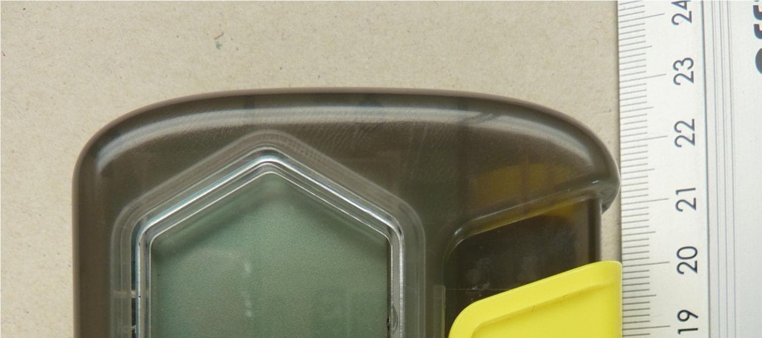
Click to zoom
Application Details
- Equipment Class
- DCD - Part 15 Low Power Transmitter Below 1705 kHz
- Date of Grant
- Jul 24, 2013
- Application Purpose
- Original Equipment
- Date of Application
- Jul 24, 2013
- Equipment Note
- Avalanche Beacon
- Frequency Range
- 0.45700000 - 0.45700000
- Company
- Black Diamond Equipment
- Country
- United States
Documents & Files
Document Text
Text extracted from the exhibit documents filed with the FCC. Open a document above to read the original.
Users Manual
08/13 MANUAL PIEPS DSP Pro | DSP SPort PREMIUM ALPINE PERfoRMANcE Congratulations on having purchased a PIEPS DSP PRO/DSP SPORT. The PIEPS DSP PRO/DSP SPORT is a digital 3-antenna transceiver designed to be the easiest to use in a companion rescue. Equipped with DSP technology (Digital Signal Processing) and a triple-antenna-search system, the PIEPS DSP PRO/DSP SPORT not only offers a maximum circular range, but also simplifies the rescue, especially in a case with multiple burials. The new functions of the Intelligent Transmitter also support the user in SEND-mode at a maximum – you will be found faster with your PIEPS DSP PRO/DSP SPORT! A transceiver cannot protect you against avalanches! Obtaining the proper level of avalanche education, and regular practicing with all avalanche rescue equipment is essential to carry out a safe, and effective rescue. The procedures and instructions described refer solely to specific applications in connection with PIEPS DSP PRO/DSP SPORT. The basic rules of conduct in case of an emergency – as defined in the relevant specialist publications and in training sessions – must be observed without fail. DEAr WINtEr SPortS ENtHUSIASt! 7 11 33 16 15 11 10 9 8 14 13 12 5 66 45 22 PIEPS DSP Pro PIEPS DSP SPort 1 LCD-Display (backlight) 2 Main switch OFF-SEND-SEARCH 3 Lock 4 SCAN Button * 5 MARK Button 6 Loudspeaker 7 Direction Indicator 8 Numeric Information 9 Battery Level 10 Display “SEND” 11 Number of Burials 12 Current Sending Antenna 13 Meter-indication at SCAN * 14 Frequency measurement * 15 TX600-Mode * 16 Inclinometer * * Only for DSP PRO DE EN ES FR IT CZ SK SLO RU ハ 08/13 |21 Carrying recommendation: PIEPS recommends carrying the PIEPS DSP PRO/DSP SPORT using the supplied carrying harness. The neoprene-material is water repellent, and the “Quick-pull-System” enables you to access the PIEPS DSP PRO/DSP SPORT very quickly in case of emergency. Step 1: Putting on the carrying harness, place the shoulder strap loop over head and shoulder. Lead the body strap around your back, fix the quick fastener and adjust to the proper length. Step 2: Switch on the PIEPS DSP PRO/ DSP SPORT and wait for the results of the self-check. Step 3: Put the PIEPS DSP PRO/DSP SPORT back into the carrying system and enjoy your tour. QUICKStArt IN 3 StEPS Your PIEPS DSP PRO/DSP SPORT is ready to use directly out of the box! There is also the option to carry the PIEPS DSP PRO/ DSP SPORT with the supplied hand loop in a securely closeable trouser pocket without a protective case. The hand loop can be fixed around your wrist during the search to rule out losing the PIEPS DSP PRO/DSP SPORT. „Quick-Pull-System“ | 08/1322 BAttErIES The battery compartment is located on the backside of the housing. The safety screw connection can be easily opened and closed using a coin. Only use battery type LR03/AAA and always replace all 3 batteries with new ones of the same type. Never use rechargeable batteries and always change all batteries at the same time! The battery indication is based on measuring the actual battery voltage. Due to the temperature influence the actual battery voltage may vary. A change from cold (outdoor) to warm (mountain hut) the battery capacity obviously recovers. IMPortANt! During a longer time of no use (e.g. summer) the batteries have to be taken out of the PIEPS DSP PRO/DSP SPORT. Damages because of leaked batteries are not included in the warranty. DSP PRODSP SPORT 3/3 filled 400–250 h SEND200–120 h SEND 2/3 filled 250–120 h SEND120–60 h SEND 1/3 filled 120–20 h SEND60–20 h SEND empty20 h SEND (+10°C) + 1 h SEARCH (-10°C) empty, flashinglast reserve, transceiver can be switched off at anytime Electromagnetic Compatibility (EMC) and PIEPS Auto-Antenna-Switch: All beacons are very sensitive against electrical and magnetic interferences. Due to this, it’s a recommendation from all manufacturers that minimum distances should be maintained between avalanche beacons and electronic, magnetic or metallic influences (like radios, mobile phones, MP3-players, bunch of keys)! PIEPS recommends: Minimum distance in SEND-mode: 20 cm | SEARCH-mode: 50 cm Your PIEPS DSP PRO/DSP SPORT has an Auto-Antenna-Switch included: If there is an external influence the strongest antenna will begin transmitting. Further information can be found in the chapter “Intelligent Transmitter”. DE EN ES FR IT CZ SK SLO RU ハ 08/13 |23 SWItCHING oN | SELF-CHECK Press the main switch lock and push the main switch to the position “SEND“ or “SEARCH“. The PIEPS DSP PRO/DSP SPORT is now in SEND- or SEARCH-mode. During power-on, the PIEPS DSP PRO/DSP SPORT will carry out a self-check. The transmitting frequency, all antennas, amplifiers, and processors are tested and the latest firmware is displayed. During the self-check, a minimum distance of 5 meters should be maintained to other beacons, and any electronic or magnetic interference. If the self-check is successful, “OK“ is indicated on the display. In the event of a device warning, an alert signal sounds and the display indicates “E“ in combination with a warning-code (overview table in chapter warning-codes). If the warnings are still shown in an interference- free area the PIEPS DSP PRO/DSP SPORT is not fully functional. Bring your PIEPS DSP PRO/DSP SPORT to a PIEPS authorized service center. IMPortANt! In Addition to the complex self-check a beacon-group-check is strongly recommended before each tour! Display Firmware-Version Display Self-check OK Display Self-check error | 08/1324 The Intelligent Transmitter – Gives maximum support in SEND-mode In SEND-mode there are functions working in the background of PIEPS DSP PRO/DSP SPORT that help to be found faster and more efficiently in case of an emergency. Auto-Antenna-Switch The maximum range where a rescuer can locate a PIEPS DSP PRO/DSP SPORT with another beacon depends strongly on the signal strength of the transmitting beacon. If the transmitting antenna is negatively influenced through external devices …
Text truncated - open the document above for the full version.
External Photos
ANNEX B EXTERNAL PICTURES Test engineer: Raimund BLASK Report Number: F131845E3 Date of issue: 19 July 2013 Order Number: 13-111845 page 1 of 4 131845eut1.JPG: EUT, front-view ANNEX B EXTERNAL PICTURES Test engineer: Raimund BLASK Report Number: F131845E3 Date of issue: 19 July 2013 Order Number: 13-111845 page 2 of 4 131845eut2.JPG: EUT, rear-view ANNEX B EXTERNAL PICTURES Test engineer: Raimund BLASK Report Number: F131845E3 Date of issue: 19 July 2013 Order Number: 13-111845 page 3 of 4 131845eut3.JPG: EUT, 3D-view ANNEX B EXTERNAL PICTURES Test engineer: Raimund BLASK Report Number: F131845E3 Date of issue: 19 July 2013 Order Number: 13-111845 page 4 of 4 131845eut4.JPG: EUT, 3D-view
ID Label/Location Info
Lable Location Info 12345678901234 Model: PIEPS DSP02 FCC ID: REMDSP02 IC: 7262A‐DSP02
Internal Photos
ANNEX C INTERNAL PICTURES Test engineer: Raimund BLASK Report Number: F131845E3 Date of issue: 9 July 2013 Order Number: 13-111845 page 1 of 5 131845eut1.JPG: EUT, internal-view ANNEX C INTERNAL PICTURES Test engineer: Raimund BLASK Report Number: F131845E3 Date of issue: 9 July 2013 Order Number: 13-111845 page 2 of 5 131845eut2.JPG: EUT, internal-view ANNEX C INTERNAL PICTURES Test engineer: Raimund BLASK Report Number: F131845E3 Date of issue: 9 July 2013 Order Number: 13-111845 page 3 of 5 131845eut3.JPG: EUT, PCB front-view ANNEX C INTERNAL PICTURES Test engineer: Raimund BLASK Report Number: F131845E3 Date of issue: 9 July 2013 Order Number: 13-111845 page 4 of 5 131845eut4.JPG: EUT, PCB front-view ANNEX C INTERNAL PICTURES Test engineer: Raimund BLASK Report Number: F131845E3 Date of issue: 9 July 2013 Order Number: 13-111845 page 5 of 5 131845eut5.JPG: EUT, PCB rear-view
Test Report
Königswinkel 10 32825 Blomberg Germany Phone: +49 (0) 52 35 95 00-0 Fax: +49 (0) 52 35 95 00-10 Test Report Report Number: F131845E3 Applicant: PIEPS GmbH Manufacturer: PIEPS GmbH Equipment under Test (EUT): Avalanche Beacon “PIEPS DSP02” Laboratory (CAB) accredited by Deutsche Akkreditierungsstelle GmbH (DAkkS) in compliance with DIN EN ISO/IEC 17025 under the Reg. No. D-PL-17186-01-02. FCC Test site registration number 90877 and Industry Canada Test site registration IC3469A-1. Testengineer: Raimund BLASK Report Number: F131845E3 Date of issue: 9 July 2013 Order Number: 13-111845 page 2 of 21 REFERENCES [1] ANSI C63.4-2009 American National Standard for Methods of Measuring of Radio-Noise Emissions from Low-Voltage Electrical and Electronic Equipment in the Range of 9 kHz to 40 GHz. [2] FCC CFR 47 Part 15 (July 2013) Radio Frequency Devices [3] RSS-210 Issue 8 (December 2010) Low-power Licence-exempt Radiocommunication Devices (All Frequency Bands): Category I Equipment [4] RSS-Gen Issue 3 (December 2010) General Requirements and Information for the Certification of Radiocommunication Equipment TEST RESULT The complete test results are presented in the following. RESERVATION This test report is only valid in its original form. Any reproduction of its contents in extracts without written permission of the accredited test laboratory PHOENIX TESTLAB GmbH is prohibited. The test results herein refer only to the tested sample. PHOENIX TESTLAB GmbH is not responsible for any generalizations or conclusions drawn from these test results concerning further samples. Any modification of the tested samples is prohibited and leads to the invalidity of this test report. Each page necessarily contains the PHOENIX TESTLAB Logo and the TEST REPORT NUMBER. Testengineer: Raimund BLASK Report Number: F131845E3 Date of issue: 9 July 2013 Order Number: 13-111845 page 3 of 21 Contents : Page 1 IDENTIFICATION ................................................................................................................... 4 1.1 APPLICANT ....................................................................................................................... 4 1.2 MANUFACTURER ............................................................................................................. 4 1.3 TEST LABORATORY ........................................................................................................ 4 1.4 EUT (EQUIPMENT UNDER TEST) ................................................................................... 5 1.5 TECHNICAL DATA OF EQUIPMENT ................................................................................ 5 1.6 DATES .............................................................................................................................. 5 2 OPERATIONAL STATES ....................................................................................................... 6 3 ADDITIONAL INFORMATION (as declared by the applicant): ................................................ 6 4 OVERVIEW ............................................................................................................................ 7 5 METHODS OF MEASUREMENT ........................................................................................... 8 5.1 RADIATED EMISSIONS .................................................................................................... 8 5.2 RADIATED EMISSIONS .................................................................................................. 15 5.2.1 TEST RESULTS (RADIATED EMISSIONS) ........................................................... 15 5.2.1.1 PRELIMINARY RADIATED EMISSION MEASUREMENT (9 kHz to 30 MHz) .... 15 5.2.1.2 FINAL RADIATED EMISSION MEASUREMENT (9 kHz to 30 MHz) .................. 17 5.2.1.3 PRELIMINARY MEASUREMENT (30 MHz to 1 GHz) ........................................ 18 6 TEST EQUIPMENT AND ANCILLARIES USED FOR TESTS .............................................. 20 7 REPORT HISTORY ............................................................................................................. 20 8 LIST OF ANNEXES .............................................................................................................. 21 Testengineer: Raimund BLASK Report Number: F131845E3 Date of issue: 9 July 2013 Order Number: 13-111845 page 4 of 21 1 IDENTIFICATION 1.1 APPLICANT Name: PIEPS GmbH Address: Parkring 4 8403 Lebring Country: Austria Name for contact purposes: Mr. Wolfgang Platzer Phone: +43-3182-52556-21 Fax: +43-3182-52556-19 eMail Address: [email protected] 1.2 MANUFACTURER Name: PIEPS GmbH Address: Parkring 4 8403 Lebring Country: Austria Name for contact purposes: Mr. Wolfgang Platzer Phone: +43-3182-52556-21 Fax: +43-3182-52556-19 eMail Address: [email protected] 1.3 TEST LABORATORY The tests were carried out at: PHOENIX TESTLAB GmbH Königswinkel 10 32825 Blomberg Germany Accredited by Deutsche Akkreditierungsstelle GmbH (DakkS) in compliance with DIN EN ISO/IEC 17025 under the Reg. No. D-PL-17186-01-02., FCC Test site registration number 90877 and Industry Canada Test site registration IC3469A-1. Testengineer: Raimund BLASK Report Number: F131845E3 Date of issue: 9 July 2013 Order Number: 13-111845 page 5 of 21 1.4 EUT (EQUIPMENT UNDER TEST) Test object: * Avalanche Beacon Type: * DSP Pro FCC-ID: * REMDSP02 IC: * 7262-DSP02 Antenna type: * Integral H-Field-Antenna Hardware version: * Rev. 6 Software version: * 1.0 1.5 TECHNICAL DATA OF EQUIPMENT Duty cycle class: * Up to 100% Rated transmitter field strength: * 7 dBμA/m @ 10 m distance (declared by the applicant) Channel spacing: * - ITU classification: * 2K02A1A Alignment range: * 457 kHz Switching range: * 457 kHz Modulation: * A1A Double Sideband Amplitude Modulation Bit rate of transmitter: * No Data transfer Supply Voltage: * U Nom = 4.5 V U Min = 3.6 V U Max = 5.4 V Power Supply: * 4.5 V ( 3 x 1.5 V / Type AAA ) Temperature range: * -20°C to 55°C …
Text truncated - open the document above for the full version.
Test Setup Photos
ANNEX A PHOTOGRAPHS Test engineer: Raimund BLASK Report Number: F131845E3 Date of issue: 9 July 2013 Order Number: 13-131845 page 1 of 3 131845emi1.JPG: Test set-up preliminary radiated emission (H-Field) ANNEX A PHOTOGRAPHS Test engineer: Raimund BLASK Report Number: F131845E3 Date of issue: 9 July 2013 Order Number: 13-131845 page 2 of 3 131845emi2.JPG: Test set-up radiated emission (E-Field) ANNEX A PHOTOGRAPHS Test engineer: Raimund BLASK Report Number: F131845E3 Date of issue: 9 July 2013 Order Number: 13-131845 page 3 of 3 131845emi3.JPG: Test set-up final radiated emission (H-Field)
Contact Information
Applicant
Robin -- Rocco(Quality Engineering Manager)
Test Firm
Phoenix TestLab GmbHH. Altmaier
Technical Specifications
| # | Rule Parts | Frequency Range | Power Output |
|---|---|---|---|
| 1 | 15C | 0.457 MHz - 0.457 MHz | - |
Other Applications from Black Diamond Equipment
REMDSP08
Oct 24, 2022Avalanche Transceivers
Equipment Class
DTS - Digital Transmission System
REMLVS05
Feb 21, 2021Avalanche Beacon
Equipment Class
DCD - Part 15 Low Power Transmitter Below 1705 kHz
REMGLOBF01
Sep 25, 2012Wireless Satellite Beacon
Equipment Class
JBP - Part 15 Class B Computing Device Peripheral
REMVECTOR01
Dec 19, 2011Avalanche Beacon VECTOR
Equipment Class
DCD - Part 15 Low Power Transmitter Below 1705 kHz
REMTX600
Dec 19, 2011Avalanche Beacon TX600
Equipment Class
DCD - Part 15 Low Power Transmitter Below 1705 kHz