RFAAND5061TARDVD /CD Player w/AV Receiver (Wireless Sub Woofer)
Eastech Electronics (Taiwan) Inc.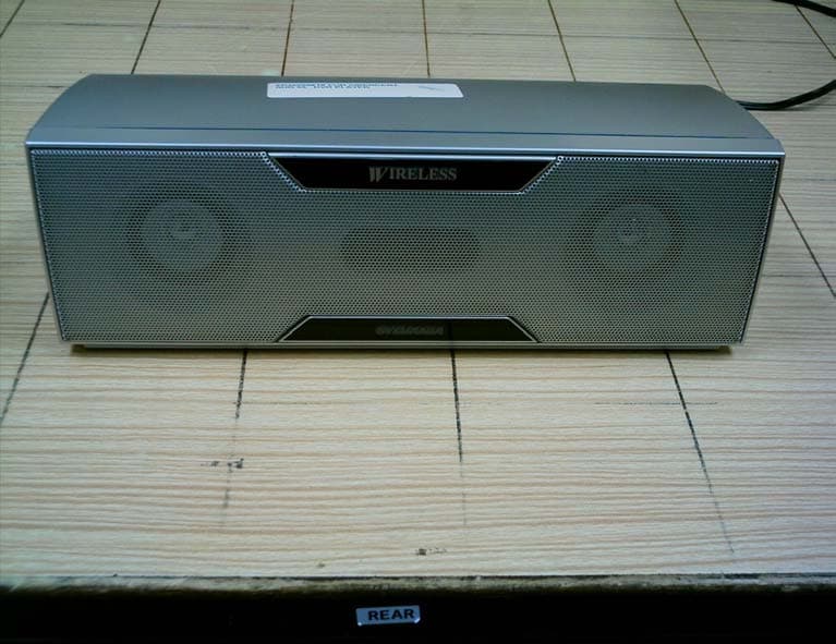
Click to zoom
Application Details
- Equipment Class
- DSS - Part 15 Spread Spectrum Transmitter
- Date of Grant
- Sep 29, 2005
- Application Purpose
- Original Equipment
- Date of Application
- Sep 29, 2005
- Equipment Note
- DVD /CD Player w/AV Receiver (Wireless Sub Woofer)
- Frequency Range
- 2403.00000000 - 2480.00000000
- Country
- Taiwan
Documents & Files
Document Text
Text extracted from the exhibit documents filed with the FCC. Open a document above to read the original.
Users Manual
• BUS cables 8 Pin:(WX1X6000-007)and 10 Pin: (WX1X6000-006) • Foot x 2 (1VM421328) • Stand x 2 (Silver:1VM422542) (Black:1VM422733) • FM wire antenna (WX1E9000-081) • AM loop antenna (UANTAMALH002) Precautions Functions Setup AV Receiver Information Owner’s Manual Please read before using this system. DVD/CD Player with AV Receiver HT6051F / HT6051FB INSTRUCCIONES EN ESPAÑOL INCLUIDAS. If you need additional operating assistance after reading this owner’s manual, please call TOLL FREE : 1-800-968-3429 or visit our web site at http://www.SylvaniaConsumerElectronics.com Table of Contents • Remote control with two AA batteries (Silver: NB140UD) (Black: NB144UD) • Audio/Video cables (WPZ0102TM015/ WPZ0102LTE01/ WPZ0102CAB01) • Owner’s Manual (1VMN21407) • AV Receiver (Silver: X6000UD) (Black: X6003UD) • Speaker Unit (Silver: USPUSPKHYE07) (Black: USPUSPKHYE09) Supplied Accessory Owner's Manual POWER ROCK POPS CLASSIC JAZZ BASS BOOST VOLUME Precautions Laser Safety. . . . . . . . . . . . . . . . . . . . . . . . . . . . . . . . . . . . . . . . 2 ■ IMPORTANT SAFEGUARDS . . . . . . . . . . . . . . . . . . . . . . . . . . . 3 Avoid the Hazards of Electrical Shock and Fire . . . . . . . . . . . . . . 4 Moisture Condensation Warning . . . . . . . . . . . . . . . . . . . . . . . . . 4 Installation Location . . . . . . . . . . . . . . . . . . . . . . . . . . . . . . . . . . 4 About Copyright . . . . . . . . . . . . . . . . . . . . . . . . . . . . . . . . . . . . . 4 Notice for Progressive Scan Outputs . . . . . . . . . . . . . . . . . . . . . 4 Symbols Used in This Manual . . . . . . . . . . . . . . . . . . . . . . . . . . 4 Maintenance . . . . . . . . . . . . . . . . . . . . . . . . . . . . . . . . . . . . . . . 4 ■ About the Discs . . . . . . . . . . . . . . . . . . . . . . . . . . . . . . . . . . . . 5 Playable Discs . . . . . . . . . . . . . . . . . . . . . . . . . . . . . . . . . . . . . . 5 Unplayable Discs . . . . . . . . . . . . . . . . . . . . . . . . . . . . . . . . . . . . 5 Setup ■ Functional Overview . . . . . . . . . . . . . . . . . . . . . . . . . . . . . . . . . 6 Front / Rear Panel Controls . . . . . . . . . . . . . . . . . . . . . . . . . . . . 6 Setting the DVD/CD Player (the AV Receiver) . . . . . . . . . . . . . . . 7 Speaker Setup . . . . . . . . . . . . . . . . . . . . . . . . . . . . . . . . . . . . . . 7 ■ About the Remote Control . . . . . . . . . . . . . . . . . . . . . . . . . . . . 7 Installing the Batteries for the Remote Control . . . . . . . . . . . . . . 7 Remote Control Operation for the DVD/CD Player . . . . . . . . . . . 8 Remote Control Operation for the AV Receiver . . . . . . . . . . . . . . 8 ■ Connections . . . . . . . . . . . . . . . . . . . . . . . . . . . . . . . . . . . . . . . 9 Connection to the AV Receiver and the Speaker Unit . . . . . . . . . 9 Connection to a TV. . . . . . . . . . . . . . . . . . . . . . . . . . . . . . . . . . 10 RF Modulator Connection (If Your TV Does Not Have A/V Input Jacks.) . . . . . . . . . . . . . . 11 Functions ■ Playback . . . . . . . . . . . . . . . . . . . . . . . . . . . . . . . . . . . . . . . . . 12 ■ MP3/WMA Playback . . . . . . . . . . . . . . . . . . . . . . . . . . . . . . . . 13 ■ Search Function . . . . . . . . . . . . . . . . . . . . . . . . . . . . . . . . . . . 13 Using Track Search . . . . . . . . . . . . . . . . . . . . . . . . . . . . . . . . . 13 Using Title / Chapter Search. . . . . . . . . . . . . . . . . . . . . . . . . . . 13 Using Time Search . . . . . . . . . . . . . . . . . . . . . . . . . . . . . . . . . . 13 ■ On-Screen Display . . . . . . . . . . . . . . . . . . . . . . . . . . . . . . . . . 14 ■ Marker Setup. . . . . . . . . . . . . . . . . . . . . . . . . . . . . . . . . . . . . . 14 ■ Repeat / Random / Programmed Playback . . . . . . . . . . . . . . 15 Repeat Playback . . . . . . . . . . . . . . . . . . . . . . . . . . . . . . . . . . . 15 Random Playback . . . . . . . . . . . . . . . . . . . . . . . . . . . . . . . . . . 15 Programmed Playback . . . . . . . . . . . . . . . . . . . . . . . . . . . . . . . 15 ■ Special Settings . . . . . . . . . . . . . . . . . . . . . . . . . . . . . . . . . . . 16 Subtitle Language . . . . . . . . . . . . . . . . . . . . . . . . . . . . . . . . . . 16 Audio Language . . . . . . . . . . . . . . . . . . . . . . . . . . . . . . . . . . . . 16 Camera Angles . . . . . . . . . . . . . . . . . . . . . . . . . . . . . . . . . . . . 16 Black Level Setting . . . . . . . . . . . . . . . . . . . . . . . . . . . . . . . . . . 16 Stereo Sound Mode . . . . . . . . . . . . . . . . . . . . . . . . . . . . . . . . . 16 Dolby Pro Logic II. . . . . . . . . . . . . . . . . . . . . . . . . . . . . . . . . . . 16 ■ DVD Setup . . . . . . . . . . . . . . . . . . . . . . . . . . . . . . . . . . . . . . . . 17 SETUP Menu . . . . . . . . . . . . . . . . . . . . . . . . . . . . . . . . . . . . . . 17 LANGUAGE Setting . . . . . . . . . . . . . . . . . . . . . . . . . . . . . . . . . 18 DISPLAY Setting . . . . . . . . . . . . . . . . . . . . . . . . . . . . . . . . . . . 18 AUDIO Setting . . . . . . . . . . . . . . . . . . . . . . . . . . . . . . . . . . . . . 19 PARENTAL Setting . . . . . . . . . . . . . . . . . . . . . . . . . . . . . . . . . . 20 OTHERS Setting . . . . . . . . . . . . . . . . . . . . . . . . . . . . . . . . . . . 20 AV Receiver ■ AM/FM Radio. . . . . . . . . . . . . . . . . . . . . . . . . . . . . . . . . . . . . . 21 To Connect AM/FM Antenna. . . . . . . . . . . . . . . . . . . . . . . . . . . 21 Preset Radio Stations. . . . . . . . . . . . . . . . . . . . . . . . . . . . . . . . 21 Selecting Radio Stations . . . . . . . . . . . . . . . . . . . . . . . . . . . . . 21 ■ Sound Setting . . . . . . . . . . . . . . . . . . . . . . . . . . . . . . . . . . . . . 22 Digital Sound . . . . . . . . . . . . . . . . . . . . . . . . . . . . . . . . . . . . . . 22 Bass Boost. . . . . . . . . . . . . . . . . . . . . . . . . . . . . . . . . . . . . . . . 22 Surround Sound . . . . . . …
Text truncated - open the document above for the full version.
External Photos
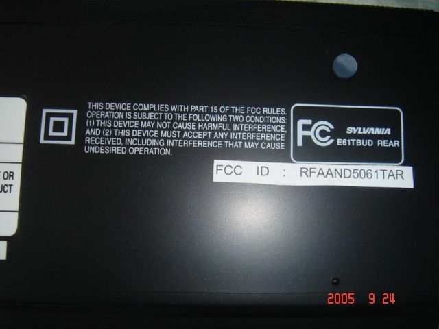
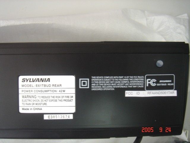
Front View Front View Rear View EUT PHOTOGRAPHS FOR CENTER SPEAKER Front View Rear View EUT PHOTOGRAPHS FOR FRONT SPEAKER Front View Rear View EUT PHOTOGRAPHS FOR AV RECEIVER Front View Rear View EUT PHOTOGRAPHS FOR DVD / CD PLAYER Front View Rear View EUT PHOTOGRAPHS FOR WIRELESS REAR SPEAKER Front View Rear View
Internal Photos
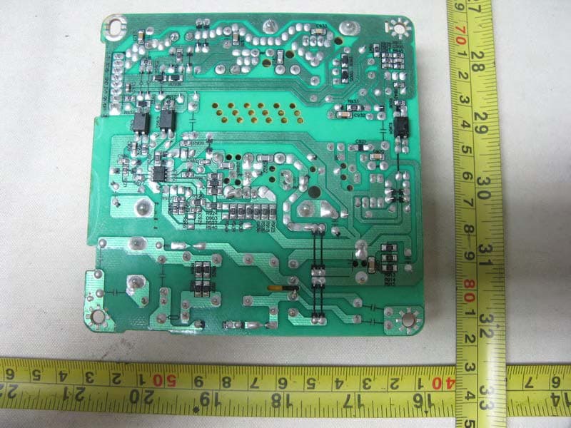
Internal View PCB PHOTOGRAPHS FOR SUBWOOFER PCB PHOTOGRAPHS FOR SUBWOOFER RF MODULE PCB PHOTOGRAPHS FOR SUBWOOFER RF MODULE RF Antenna PCB PHOTOGRAPHS FOR SUBWOOFER RF MODULE (RF SHIELD REMOVED) INTERNAL PHOTOGRAPHS FOR CENTER SPEAKER Internal View 1 Internal View 2 INTERNAL PHOTOGRAPHS FOR FRONT SPEAKER Internal View 1 Internal View 2 EUT PHOTOGRAPHS FOR AV RECEIVER PCB PHOTOGRAPHS FOR AV RECEIVER (LCD PORTION) Trace View PCB PHOTOGRAPHS FOR AV RECEIVER (LCD PORTION) Component View PCB PHOTOGRAPHS FOR AV RECEIVER (MAIN BOARD) Trace View PCB PHOTOGRAPHS FOR AV RECEIVER (MAIN BOARD) Component View INTERNAL PHOTOGRAPHS FOR DVD / CD PLAYER Internal View PCB PHOTOGRAPHS FOR DVD / CD PLAYER Trace View PCB PHOTOGRAPHS FOR DVD / CD PLAYER Component View PCB PHOTOGRAPHS FOR DVD / CD PLAYER Top View PCB PHOTOGRAPHS FOR DVD / CD PLAYER Rear View PHOTOGRAPHS FOR DVD / CD PLAYER (DVD DRIVE) Top View Rear View INTERNAL PHOTOGRAPHS FOR WIRELESS REAR SPEAKER Internal View PCB PHOTOGRAPHS FOR WIRELESS REAR SPEAKER Trace View PCB PHOTOGRAPHS FOR WIRELESS REAR SPEAKER Component View PCB PHOTOGRAPHS FOR WIRELESS REAR SPEAKER RF MODULE Trace View PCB PHOTOGRAPHS FOR WIRELESS REAR SPEAKER RF MODULE Component View RF Antenna PCB PHOTOGRAPHS FOR WIRELESS REAR SPEAKER RF MODULE (RF SHIELD REMOVED) Component View
Operational Description
Date : 7 Feb 2005 PSB Corporation CONFIDENTIAL Page 1 of 1 VConnect (Digital Wireless Audio Module) Operation Writeup The VConnect (Digital Wireless Audio Module) uses 2.4GHz Bluetooth Class 1 radio transceiver together with a baseband that employed an intelligent frequency hopping algorithm for interference avoidance called Advance Adaptive Frequency Selection (AAFS). The AAFS algorithm will test a frequency channel for interference before commencing audio data transfer. Once interference is detected during its audio data transfer process, it will exit the existing channel and switch to another unused channel. The audio transmitter is termed as a master module while an audio receiver is termed as a slave module. Both the master and slave modules are radio transceivers and they maintain synchronisation through the exchange of control data in the wireless communication protocol. The master module is in transmission for about 75% before it switches to receiver mode. Similarly the slave module is in transmission for about 25% before it switches to receiver mode. Both the master and slave modules are defined and matched by an unique 28-bit device ID address. In the master module, the module input analog audio signal is converted into digital format through an Analog to Digital Converter (ADC). The digital audio is input into the baseband for digital processing. In the baseband, the digital audio is compressed by 4 times and formatted into packets for transmission. In the slave module, once the audio data packet is received via the RF transceiver, the audio data packets are verified using Forward Error Correction (FEC). The verified audio packets are uncompressed and output in digital audio format from the baseband. Using a Digital to Audio Converter (DAC), the digital audio is converted into analog audio as the module’s output. When both the master and slave modules (with the same device ID address) are powered on, they will execute a channel scan mode to locate an unused frequency channel in the 2.4GHz ISM band. Within the 79 channels available in the 2.4GHz band, 10 pre-defined channels are not used for module pairing but are used during the channel scan mode. Both the master and slave modules will hop in a pseudo-random sequence to locate each other and will eventually pair on one of the 69 channels. After the paired modules have established a reliable communication channel (primary channel) and have begun audio content transfer, the paired modules will continuously monitor the wireless communication link quality. After about every 5ms of transmission on the primary channel, they will search and switch to another frequency channel (secondary channel) to test its wireless link quality. Thereafter the modules will hop back to the primary channel to continue audio transfer. If an interference source occupies the same channel, the existing channel becomes unreliable and the error detection from the FEC block exceeds a preset error threshold. The modules will immediately and automatically hop to the secondary channel which will now become the primary channel for audio content transfer. Over a period of time, there will be equal usage of the frequency channels by the modules because the interference source may also hop or exist intermittently. And the communication channel will not remain unchanged for more than 400ms.
Operational Description
PSB Corporation CONFIDENTIAL Page 1 of 3 Pseudorandom Frequency Hopping Sequence Describe how the hopping sequence is generated. Provide an example of the hopping sequence channels, in order to demonstrate that the sequence meets the requirement specified in the definition of a frequency hopping spread spectrum system, found in Section 2.1. When both the master and slave modules are power up, the master and slave modules will enter into a channel scan mode where initially both the master and slave will hop on 10 pre- defined channels in pseudo-random sequence to search for each other. These pre-defined channels are distributed equally over the 79 channels. The hopping sequence is generated through a pseudo-random generator. In the figure below, both the master and slave hops on the 10 predefined channels in a pseudo-random random sequence to locate each other. The master hops at every 625μs while the slave hops at every 160ms. Once the master module detected the presence of a slave module with an identical unique 28-bit device ID in the initial channel scan mode, both modules will continue to hop on the remaining 69 channels to establish a reliable channel link to commence wireless audio delivery. Based on the unique 28-bit device ID which both the paired master and slave have in common, both the master and slave will hop in synchronization to test the communication link before starting the audio content delivery. The wireless link quality is determined from the number of errors generated in the Forward Error Correction (FEC) computation. If there is no error or the number of error is below a preset threshold, the wireless link is considered as good.. Master located Slave TimeTime Frequency Frequency Initial Channel Scan Master Slave PSB Corporation CONFIDENTIAL Page 2 of 3 Equal Hopping Frequency Use Describe how each individual EUT meets the requirement that each of its hopping channels is used equally on average (e.g., that each new transmission event begins on the next channel in the hopping sequence after the final channel used in the previous transmission event). When an interference source interferes with the communication channel which the paired modules are, the existing communication channel becomes unreliable and the error detection from the FEC computation exceeds a preset error threshold. The modules will immediately and automatically hop to the secondary channel which will now become the primary channel to continue audio content transfer. Meanwhile the modules will continue to hop to search for a secondary channel. Over a period of time, there will be equal usage of the frequency channels by the modules because the interference source may also hop or exist intermittently. And the communication channel will not remain unchanged for more than 400ms. System Receiver Hopping Capability Describe how the associated receiver(s) has the ability to shift frequencies in synchronization with the transmitted signals. After the master and the slave have been paired and started audio delivery on the primary channel, they will hop to another channel to test the communication link quality. The channel which both the master and slave hop, will depend on the unique 28 bit device ID that both the paired master and slave have in common. Once a channel with good communication link has been identified, the paired master and slave will hop to the channel (known as secondary channel) to verify the communication link at interval of about 5ms periodically. If the secondary channel link is poor, the searching for another secondary channel will be repeated. Once interference occurs on the primary channel, the paired master and slave will hop directly to the secondary channel which will now become the primary channel. The search for the secondary channel will again be repeated. System Receiver Input Bandwidth Describe how the associated receiver(s) complies with the requirement that its input bandwidth (either RF or IF) matches the bandwidth of the transmitted signal. Both the master and slave modules operate as a RF transceiver. In the wireless communication protocol, there are handshake between the master and the slave to determine the communication link quality and control of the data packet transmission. After every 3 packets of transmission, the master will switch to become a RF receiver. Similarly the slave will switch to become a RF transmitter to acknowledge the data packet received from the master module. All data packet received in the slave will be buffered for further processing such as Forward Error Correction and audio decompression. The above control will ensure the slave is able to match the transmission bandwidth of the master. PSB Corporation CONFIDENTIAL Page 3 of 3 Section 15.247(g) Describe how the EUT complies with the requirement that it be designed to be capable of operating as a true frequency hopping system. The master and slave module use GFSK modulation on the 2.4GHz wireless communication band. Based on the 28-bit unique ID in the paired modules, both the master and slave will randomly hop on one of the 69 channels for audio transmission and simultaneously hop to other channels to determine and verify a secondary channel link quality. Over a period of time, the use of the 69 channels will be evenly distributed.
Test Report
TEST REPORT Your Ref: Date: 07 Sep 2005 Our Ref: 56S050746/01Page: 1 of 67 DID: +65-6885 1459Fax: +65-6774 1459 NOTE: This report is issued subject to PSB Corporation's "Terms and Conditions Governing Technical Services". The terms and conditions governing the issue of this report are set out as attached within this report. LA-2001-0212-A LA-2001-0213-F LA-2001-0214-E LA-2001-0215-B LA-2001-0216-G LA-2001-0217-G The results reported herein have been performed in accordance with the laboratory’s terms of accreditation under the Singapore Accreditation Council - Singapore Laboratory Accreditation Scheme. Tests marked "Not SAC-SINGLAS Accredited" in this Report are not included in the SAC-SINGLAS Accreditation Schedule for our laboratory. Head Office: PSB Corporation • Testing Group • 1 Science Park Drive Singapore 118221 • Hotline:+65 6885 1333 • Fax:+65 6775 9725 • Email: [email protected] • Website: www.psbcorp.com Reg. No. : 199002667R • Regional Offices: Bangkok • Guangzhou • Jakarta • Kuala Lumpur • Qingdao • Shanghai • Tianjin FORMAL REPORT ON TESTING IN ACCORDANCE WITH FCC Parts 15B & C : 2005 OF A DVD/CD PLAYER WITH AV RECEIVER [ Model : E61TAUD ] [ FCC ID : RFAAND5061TA ] TEST FACILITY Telecoms & EMC, Testing Group, PSB Corporation Pte Ltd 1 Science Park Drive, Singapore 118221 FCC REG. NO. 90937 (3m & 10m OATS) 99142 (10m Anechoic Chamber) 871638 (5m Anechoic Chamber) 325572 (10m Anechoic Chamber) IND. CANADA REG. NO. IC 4257 (10m Anechoic Chamber) PREPARED FOR Eastech Electronics (Taiwan) Inc 13/F , No.99.Sec.1 ,Nankan Road, Luchu shiang, Taoyuan Hsien, Taiwan , R.O.C Tel : 886-3-3116686Fax : 886-3-3116687 JOB NUMBER 56S050746 TEST PERIOD 24 Aug 2005 – 01 Sep 2005 PREPARED BYAPPROVED BY ____________________ Dylan Lin Choon Hwa Associate Engineer ____________________ Lim Cher Hwee Product manager 56S050746/01 Eastech Electronics (Taiwan) IncPage 2 of 67 DVD / CD Player with AV Receiver [ Model : E61TAUD ] [ FCC ID : RFAAND5061TA ] TABLE OF CONTENTS TEST SUMMARY PRODUCT DESCRIPTION SUPPORTING EQUIPMENT DESCRIPTION EUT OPERATING CONDITIONS CONDUCTED EMISSION TEST RADIATED EMISSION TEST CARRIER FREQUENCY SEPARATION TEST SPECTRUM BANDWIDTH (20dB BANDWIDTH MEASUREMENT) TEST NUMBER OF HOPPING FREQUENCIES TEST AVERAGE FREQUENCY DWELL TIME TEST MAXIMUM PEAK POWER TEST RF CONDUCTED SPURIOUS EMISSIONS TEST BAND EDGE COMPLIANCE TEST PEAK POWER SPECTRAL DENSITY TEST MAXIMUM PERMISSIBLE EXPOSURE (MPE) TEST DUTY CYCLE FACTOR COMPUTATION ANNEX A- EUT PHOTOGRAPHS / DIAGRAMS ANNEX B- FCC LABEL & POSITION ANNEX C- USER MANUAL, TECHNICAL DESCRIPTION, BLOCK & CIRCUIT DIAGRAMS 56S050746/01 Eastech Electronics (Taiwan) IncPage 3 of 67 DVD / CD Player with AV Receiver [ Model : E61TAUD ] [ FCC ID : RFAAND5061TA ] TEST SUMMARY The product was tested in accordance with the customer's specifications. Test Results Summary Test StandardDescriptionPass / Fail FCC Part 15: 2005 15.107(a), 15.207Conducted EmissionsPass 15.109(a), 15.205, 15.209 Radiated Emissions (Spurious Emissions inclusive Restricted Bands Requirement) Pass Carrier Frequency SeparationPass15.247(a)(1) Spectrum Bandwidth (20dB Bandwidth Measurement) Pass Number of Hopping FrequenciesPass15.247(a)(1)(iii) Average Frequency Dwell TimePass 15.247(b)(1)Maximum Peak PowerPass 15.247(d)RF Conducted Spurious EmissionsPass 15.247(d)Band Edge CompliancePass 15.247(e)Peak Power Spectral DensityPass 1.1310Maximum Permissible Exposure Pass 15.35(c)Duty Cycle Factor ComputationRefer to pages 65 and 66 for details 56S050746/01 Eastech Electronics (Taiwan) IncPage 4 of 67 DVD / CD Player with AV Receiver [ Model : E61TAUD ] [ FCC ID : RFAAND5061TA ] TEST SUMMARY Notes 1.Three channels as listed below, which respectively represent the lower, middle and upper channels of the equipment under test (EUT) were chosen and tested. For each channel, the EUT was configured to operate in the test mode. Transmit Channel Frequency (GHz) Channel 12.403 Channel 392.441 Channel 782.480 2.All the measurements in section 15.247 were done based on conducted measurements. 3.The EUT is a Class B device when in non-transmitting state and meets the FCC Part15B Class B requirements. 4. For radiated emissions test, the EUT was tested with the RF antenna port terminated with a 75 Ω terminator as the measured RF antenna power was less than 2nW. Modifications The EUT was brought to compliance to Conducted Emissions test removing a capacitor (C1007) from the AV receiver. 56S050746/01 Eastech Electronics (Taiwan) IncPage 5 of 67 DVD / CD Player with AV Receiver [ Model : E61TAUD ] [ FCC ID : RFAAND5061TA ] PRODUCT DESCRIPTION Description: The Equipment Under Test (EUT) is a DVD / CD Player with AV Receiver. The EUT consists of following units: - 1 x AV receiver - 1 x DVD / CD player - 2 x front speakers (left and right) - 1 x center speaker - 1 x subwoofer (wireless transceiver) - 1 x wireless rear speaker (wireless transceiver) Manufacturer: Eastech Electronics ( Taiwan ) INC 13/F , No.99.Sec.1 ,Nankan Road, Luchu shiang, Taoyuan Hsien, Taiwan , R.O.C Model Number: E61TAUD FCC ID: RFAAND5061TA (for subwoofer and wireless speaker) Serial Number: E33510025 Microprocessor: Refer to manufacturers' user manual / operating manual. Operating / Transmitting Frequency : 2.400GHz to 2.480GHz Clock / Oscillator Frequency: Refer to manufacturers' user manual / operating manual. Modulation: Gaussian Frequency Shift Keying (GFSK) with BT = 0.5 Port / Connectors: Refer to manufacturers' user manual / operating manual. Rated Input Power: 110VAC 60Hz (AV receiver) 110VAC 60Hz (DVD / CD player) 110VAC 60Hz (Subwoofer) 110VAC 60Hz (Wireless rear speaker) Accessories: Nil 56S050746/01 Eastech Electronics (Taiwan) IncPage 6 of 67 DVD / CD Player with AV Receiver [ Model : E61TAUD ] [ FCC ID : RFAAND5061TA ] SUPPORTING EQUIPMENT DESCRIPTION Equipment Description (Including Brand Name) Model, Serial & FCC ID NumberCable Description (List Length, Type & Purpose) M/N: 14NX1 S/N: 40C03286 Toshiba 14” TV FCC …
Text truncated - open the document above for the full version.
Test Setup Photos
56S050746 Conducted Emissions Test Setup (Front View) 56S050746 Radiated Emissions Test Setup (Front View) 56S050746 56S050746 56S050746 56S050746 56S050746
Contact Information
Applicant
Charlotte Chen(PeM)
Test Firm
TUV SUD PSB Pte LtdHarold Tan
Technical Specifications
| # | Rule Parts | Frequency Range | Power Output |
|---|---|---|---|
| 1 | 15C | 2.40 GHz - 2.48 GHz | 24.00 mW |
Other Applications from Eastech Electronics (Taiwan) Inc.
RFARWSS5510
Jun 13, 2010IMMERSIVE SOUND HOME THEATER
Equipment Class
DXX - Part 15 Low Power Communication Device Transmitter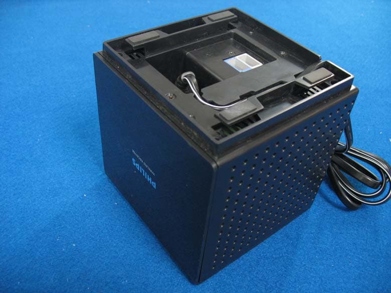
RFARWSS125
May 28, 2007DVD Home Theatre (with Radio+Wireless)
Equipment Class
DSS - Part 15 Spread Spectrum Transmitter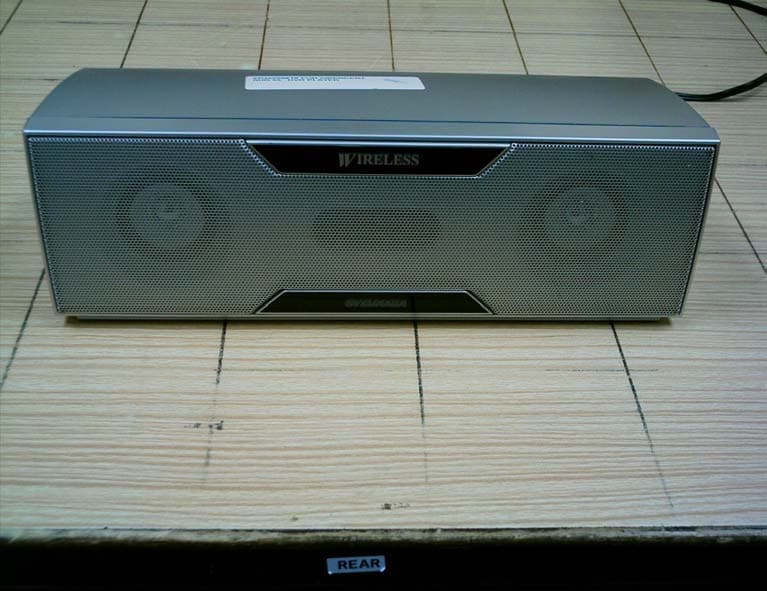
RFAAND5061TA
Sep 29, 2005DVD/ CD PLAYER WITH AV RECEIVER
Equipment Class
DSS - Part 15 Spread Spectrum Transmitter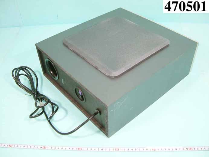
RFARTD210X
Aug 11, 2004DIGITAL 5.8GHz WIRELESS SPEAKER
Equipment Class
DXX - Part 15 Low Power Communication Device Transmitter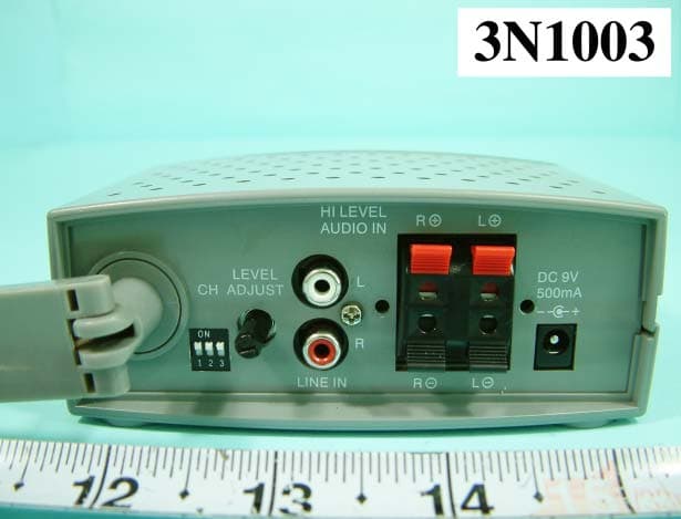
RFATL901X
Dec 07, 2003DIGITAL WIRELESS AUDIO LINK TRANSCEIVER
Equipment Class
DXX - Part 15 Low Power Communication Device Transmitter