RFATL901XDIGITAL WIRELESS AUDIO LINK TRANSCEIVER
Eastech Electronics (Taiwan) Inc.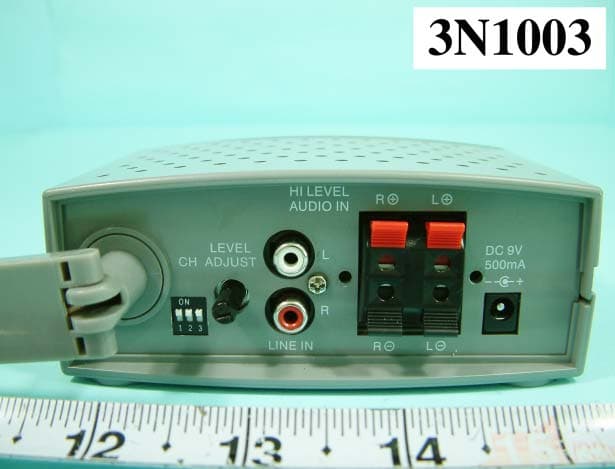
Click to zoom
Application Details
- Equipment Class
- DXX - Part 15 Low Power Communication Device Transmitter
- Date of Grant
- Dec 07, 2003
- Application Purpose
- Original Equipment
- Date of Application
- Dec 07, 2003
- Equipment Note
- DIGITAL WIRELESS AUDIO LINK TRANSCEIVER
- Frequency Range
- 5735.00000000 - 5835.00000000
- Country
- Taiwan
Documents & Files
Document Text
Text extracted from the exhibit documents filed with the FCC. Open a document above to read the original.
Users Manual
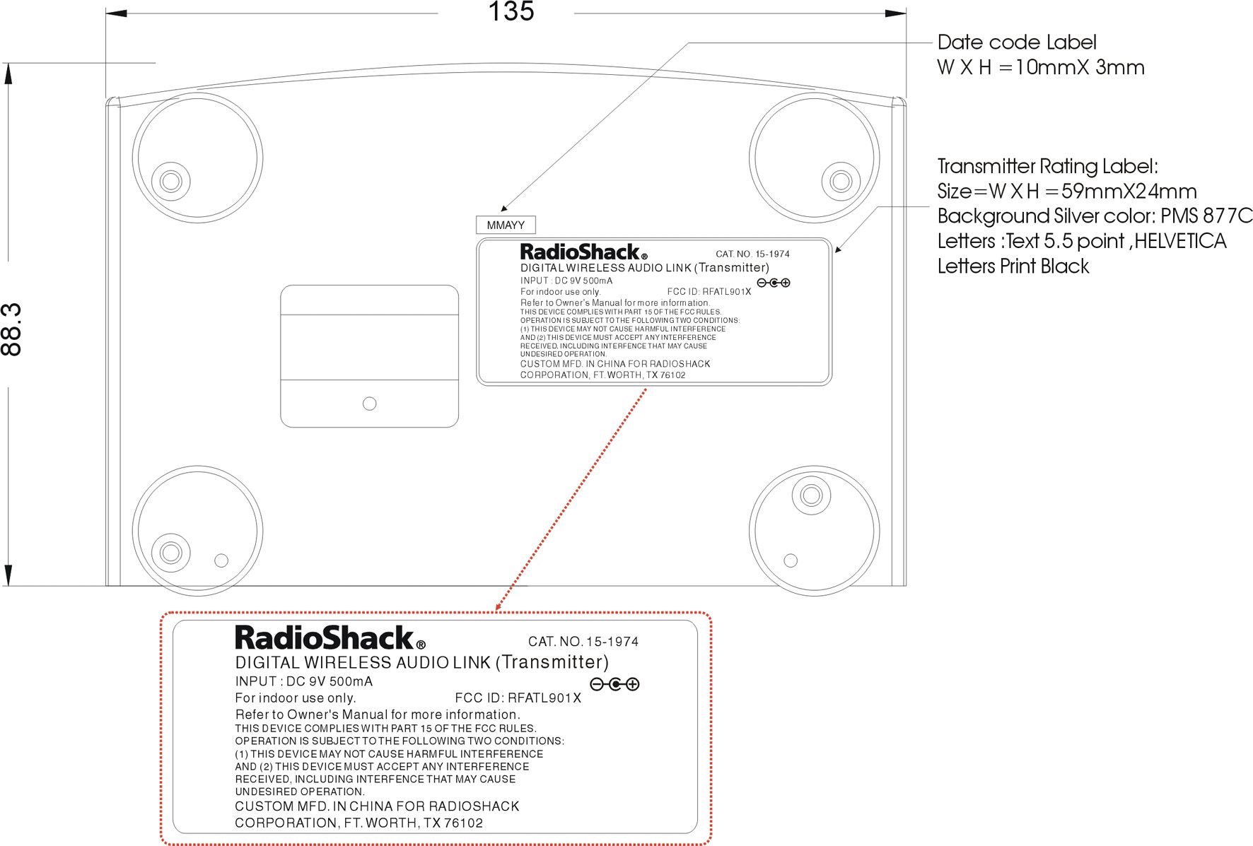
©2003 RadioShack Corporation. All Rights Reserved. RadioShack and RadioShack.com are trademarks used by RadioShack Corporation. OWNER’S MANUAL — Please read before using this equipment. www.radioshack.com SM This wireless transmitter and receiver system use the latest 5.8 GHz technology that travels through walls, floors, ceilings and other obstacles, delivering high quality sound for your home theater system’s rear surround speakers. Using this wireless system, you will experience movie theater quality sound in your own home using your current home theater surround system. We have designed this system for use with your surround sound home theater system to enhance the quality of the sound and balance coming from your speakers. You can now eliminate running long speaker wires through your rooms, while enhancing the sound coming from those speakers. How It Works The transmitter converts the audio signal from your audio source into a 5.8GHz radio frequency and transmits it to the receiver. The receiver will pick up the best signal from one of its two antennas and convert the signal back to its original form. Using a powerful amplifier, the signal is passed to your connected rear surround speakers. The result is an enhanced sound quality resulting in a theater quality surround sound experience. This system is compatible with most audio sources such as televisions, VCRs, stereo receivers/amplifiers, CD players, and personal stereos. This unit allows you to listen to wired speakers in any room in the house when a two-channel source is connected to the transmitter. The audio link system also tracks the volume setting of your audio source, so that when you increase or decrease the volume on the audio source, the link’s connected speakers respond accordingly. Some of this system’s other features include: • 6 user-adjustable channels • 2 diversity receiver antennas for optimal audio reception. • Adjustable speaker and line level input control • 256 option personal ID Code • Ideal for Dolby 5.1 Digital, Pro Logic II, DTS, SCAD and DVD Audio Systems • Provides digital transmission for superb audio clarity • Immunetointerferencefrommicrowave ovens and other popular 2.4GHz equipment • Signal range of 30 feet RECEIVER TRANSMITTER STANDBY / ON/OFF —Press to toggle between standby mode and power on. LED —Lights red when the transmitter is in power on mode, and turns green when in standby mode. POWER/PUSH OFF — Press to power the receiver on or off. Power LED —Lights red when the receiver is powered on. Signal LED —This green LED flashes when the receiver is searching for a signal from the transmitter. It glows steadier and brighter as the signal strength increases. VOLUME —Turn to adjust sound level of the connected surround speakers. You may need to adjust your A/V receiver’s volume for balance. PACKAGE CONTENTS • Transmitter • Speaker wire (for transmitter only) • Receiver • AC adapter • Adjustable stand • Owner’s Manual • Warranty The lightning symbol is intended to alert you to the presence of uninsulated dangerous voltage within this product’s enclosure that might be of sufficient magnitudetoconstituteariskofelectricshock.Donot open the product’s case. The exclamation symbol is intended to inform you that important operating and maintenance instructions are included in the literature accompanying this product. WARNING:Toreducetheriskoffireorshockhazard, do not expose this product to rain or moisture. CAUTION CAUTION:TO REDUCE THE RISK OF ELECTRIC SHOCK, DO NOT REMOVE COVER OR BACK. NO USER- SERVICEABLE PARTS INSIDE. REFER SERVICING TO QUALIFIED PERSONNEL. RISK OF ELECTRIC SHOCK DO NOT OPEN ! ! ! IMPORTANT ! If an icon appears at the end of a paragraph, go to the box on that page with the corresponding icon for pertinent information. o —Warning ! —ImportantÔ—Note Wireless 5.8 GHz Digital Audio Link 15-1974 15-1974.fm Page 1 Tuesday, September 9, 2003 3:14 PM 2 IMPORTANT SAFETY INFORMATION FOR YOUR SAFETY, READ AND RETAIN ALL SAFETY AND OPERATING INSTRUCTIONS. HEED ALL WARNINGS IN THIS MANUAL AND ON THE UNIT. POWER SOURCE To avoid any malfunctions of the unit, and to protect against electric shock, fire or personal injury, please observe the following • This system has been designed to work with 120-volt AC current. Connection to a line voltage other than that may create a safety and fire hazard and may damage the system. If you are unsure of the type of power supply to your home, consult your local dealer or power company. • Hold the plug firmly when connecting or disconnecting the power cord to the wall outlet. • Do not run power cords under rugs or carpets or place heavy objects on them. • Damaged or deformed power cords are hazardous and should be replaced immediately by a qualified service technician. LOCATION • Air vents are provided in the cabinet to prevent excessive temperatures inside the unit. Do not place this unit in closed spaces, cover it, or otherwise block the vents. • Do not place this unit in direct sunlight, or near heat sources. • Keep this unit away from strong magnetic objects. • Do not use the unit in a car. The operation can not be guaranteed. CARE • Do not insert or drop anything into this unit through the air vents as this could cause serious damage, possibly resulting in fire. • Do not place any object containing water or other liquids on this unit. In the event that liquid should enter the cabinet, unplug this unit immediately and contact the retailer or service center immediately. • Do not remove the cabinet. Touching parts inside the cabinet could result in electric shock and damage to the unit. NONUSE PERIODS • When the unit is not being used, turn the power off. • When left unused for a long period of time, the unit should be unplugged from the household AC outlet. VOLUME CONTROL • Do not turn up the volume while listening to a portion with very low level input or no audio signal. The speaker may be damaged when a peak level portion is played. CLEANING • Unplug the un…
Text truncated - open the document above for the full version.
Cover Letter(s)
FEDERAL COMMUNICATIONS COMMISSION Authorization and Evaluation Division 7435 Oakland Mills Road Columbia, MD 21046 U.S.A. To whom it may concern: I, hereby, declare that the following EMI suppression components on the EUT, FCC ID: RFATL901X, will be added or layout on the mass production products. 1. Added a ferrite core on power cable.
External Photos
FCC ID: RFATL901X Number 1 FRONT SIDE OF EUT FCC ID: RFATL901X Number 2 REAR SIDE OF EUT FCC ID: RFATL901X Number 3 CLOSER LOOK OF REAR INTERFACE PORT FCC ID: RFATL901X Number 4 FRONT SIDE OF ADAPTER 1 FCC ID: RFATL901X Number 5 REAR SIDE OF ADAPTER FCC ID: RFATL901X Number 6 LABEL OF ADAPTER
Internal Photos
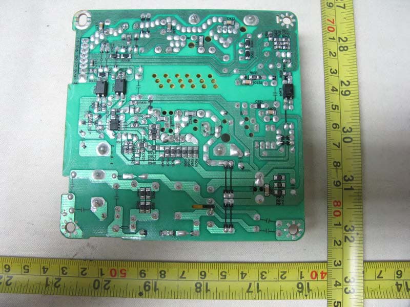
FCC ID: RFATL901X Number 1 MECHANICAL CONSTRUCTION FCC ID: RFATL901X Number 2 MECHANICAL CONSTRUCTION FCC ID: RFATL901X Number 3 MECHANICAL CONSTRUCTION FCC ID: RFATL901X Number 4 FRONT SIDE OF MAIN BOARD FCC ID: RFATL901X Number 5 REAR SIDE OF MAIN BOARD FCC ID: RFATL901X Number 6 MECHANICAL CONSTRUCTION OF MODULE BOARD FCC ID: RFATL901X Number 7 MECHANICAL CONSTRUCTION OF MODULE BOARD FCC ID: RFATL901X Number 8 FRONT SIDE OF MODULE BOARD FCC ID: RFATL901X Number 9 REAR SIDE OF MODULE BOARD FCC ID: RFATL901X Number 10 CLOSER LOOK FCC ID: RFATL901X Number 11 MECHANICAL CONSTRUCTION OF ADAPTER FCC ID: RFATL901X Number 12 FRONT SIDE OF MAIN BOARD OF ADAPTER FCC ID: RFATL901X Number 13 REAR SIDE OF MAIN BOARD OF ADAPTER
Operational Description
Wireless 5.8Ghz Digital Audio Link Model No.: TL9010 / 15-1974 Spec. Wireless spec. Item Spec Modulation Method : BPSK (Binary Phase Shift Keying) Modulation Receiver Sensitivity ,-90dBm@1E-3BER /1.92Mbps Operation Distance 10m ( clear line of sight) Antenna Port Impedance 50 Ohm Unwanted Emission ETSI EN300-220 FCC15.249 Audio Frequency 20Hz~20KHz,+/- 3 dB Audio Dynamic Range 80dB min. Audio Signal to Noise Ratio 80dB min. Audio Channel Separation 70dB min. Audio THD+ Noise <= 0.1% @ 1KHz Operating Temperature ( IC) 0~60 degree Operating Temperature ( Module) 0~35 degree Delay time 0.3 ms Multi Channel selection: 6 channels 6 channels 5.725 ~ 5.875 GHz radio frequency Tx output power 0dbm ( US) Product Description This product using an audio transceiver chipset which is a low-cost 5-GHz radio that provides a high bit rate link of 6 Mbps for wireless audio applications, such as wireless speaker. This radio solution consists of high performance all-CMOS RF transmitter (GPE110), RF receiver (GPA110), and baseband modem chips (GPE112 and GPA112) to provide the lowest cost solution. GPA110 is a highly integrated radio receiver chip that includes LNA, down conversion mixer, baseband filter, DC offset cancellation loop, VGA and synthesizer. Only a few external RF components are needed, such as bandpass filter and RF switch. This wireless transmitter and receiver system use the latest 5.8 GHz technology that travels through walls, floors, ceilings and other obstacles, delivering high quality sound for your home theater system’s rear surround speakers. Using this wireless system, you will experience movie theater quality sound in your own home using your current home theater surround system. We have designed this system for use with your surround sound home theater system to enhance the quality of the sound and balance coming from your speakers. You can now eliminate running long speaker wires through your rooms, while enhancing the sound coming from those speakers. How It Works The transmitter converts the audio signal from your audio source into a 5.8GHz radio frequency and transmits it to the receiver. The receiver will pick up the best signal from one of its two antennas and convert the signal back to its original form. Using a powerful amplifier, the signal is passed to your connected rear surround speakers. The result is an enhanced sound quality resulting in a theater quality surround sound experience. This system is compatible with most audio sources such as televisions, VCRs, stereo receivers/amplifiers, CD players, and personal stereos. This unit allows you to listen to wired speakers in any room in the house when a two-channel source is connected to the transmitter. The audio link system also tracks the volume setting of your audio source, so that when you increase or decrease the volume on the audio source, the link’s connected speakers respond accordingly. Some of this system’s other features include: • 6 user-adjustable channels • 2 diversity receiver antennas for optimal audio reception. • Adjustable speaker and line level input control • 256 option personal ID Code • Ideal for Dolby 5.1 Digital, Pro Logic II, DTS, SCAD and DVD Audio Systems • Provides digital transmission for superb audio clarity • Immune to interference from microwave ovens and other popular 2.4GHz equipment • Signal range of 30 feet
Test Report
FCC TEST REPORT Report No. : F3N1003 SPORTON International Inc. TEL : 886-2-2696-2468 FAX : 886-2-2696-2255 FCC TEST REPORT for 47 CFR, Part 15, Subpart C Equipment : 5.8GHz Digital Wireless Transceiver Model No. : 15-1974 / TL9010 / TL907 FCC ID : RFATL901X Filing Type : Certification Applicant : ATLM TAIWAN INC. 13Fl, No. 99, Sec. 1, Nankan Road, Luchu Shiang, Taoyuan Hsien 338, Taiwan, R.O.C. The test result refers exclusively to the test presented test model / sample. Without written approval of SPORTON International Inc., the test report shall not be reproduced except in full. Certificate or Test Report must not be used by the applicant to claim the product in this test report endorsement by NVLAP or any agency of U.S. government. SPORTON International Inc. 6F, No.106, Sec. 1, Hsin Tai Wu Rd., Hsi Chih, Taipei Hsien, Taiwan, R.O.C. FCC TEST REPORT Report No. : F3N1003 SPORTON International Inc. FCC ID : RFATL901X TEL : 886-2-2696-2468 Page No. : i FAX : 886-2-2696-2255 Issued Date : Nov. 18, 2003 Table of Contents History of this test report....................................................................................................................................ii CERTIFICATE OF COMPLIANCE........................................................................................................................1 1. General Description of Equipment under Test.............................................................................................2 1.1. Applicant..........................................................................................................................................................................................2 1.2. Manufacturer ...................................................................................................................................................................................2 1.3. Basic Description of Equipment under Test ....................................................................................................................................2 1.4. Feature of Equipment under Test ...................................................................................................................................................3 2. Test Configuration of Equipment under Test ...............................................................................................4 2.1. Test Manner ....................................................................................................................................................................................4 2.2. Description of Test System .............................................................................................................................................................4 2.3. Connection Diagram of Test System ..............................................................................................................................................5 3. Test Software ...................................................................................................................................................6 4. General Information of Test............................................................................................................................7 4.1. Test Facility .....................................................................................................................................................................................7 4.2. Test Voltage ....................................................................................................................................................................................7 4.3. Standard for Methods of Measurement...........................................................................................................................................7 4.4. Test in Compliance with ..................................................................................................................................................................7 4.5. Frequency Range Investigated .......................................................................................................................................................7 4.6. Test Distance ..................................................................................................................................................................................7 5. Test of Conducted Powerline .........................................................................................................................8 5.1. Major Measuring Instruments..........................................................................................................................................................8 5.2. Test Procedures ..............................................................................................................................................................................9 5.3. Typical Test Setup Layout of Conducted Powerline .....................................................................................................................10 5.4. Test Result of AC Powerline Conducted Emission .......................................................................................................................11 6. Test of Radiated Emission............................................................................................................................17 6.1. Major Measuring Instruments........................................................................................................................................................17 6.2. Test Procedures ............................................................................................................................................................................18 6.3. Typical Test Setup Layout of Radiated Emission.................................................................…
Text truncated - open the document above for the full version.
Test Setup Photos
FCC TEST REPORT Report No. : F3N1003 SPORTON International Inc. FCC ID : RFATL901X TEL : 886-2-2696-2468 Page No. : 1 of 3 FAX : 886-2-2696-2255 Issued : Nov. 18, 2003 1.1. Photographs of Conducted Powerline Test Configuration z The photographs show the configuration that generates the maximum emission. FRONT VIEW REAR VIEW FCC TEST REPORT Report No. : F3N1003 SPORTON International Inc. FCC ID : RFATL901X TEL : 886-2-2696-2468 Page No. : 2 of 3 FAX : 886-2-2696-2255 Issued : Nov. 18, 2003 SIDE VIEW FCC TEST REPORT Report No. : F3N1003 SPORTON International Inc. FCC ID : RFATL901X TEL : 886-2-2696-2468 Page No. : 3 of 3 FAX : 886-2-2696-2255 Issued : Nov. 18, 2003 1.2. Photographs of Radiated Emission Test Configuration z The photographs show the configuration that generates the maximum emission. FRONT VIEW REAR VIEW
Contact Information
Applicant
Charlotte Chen(PeM)
Test Firm
Sporton International Inc.Kathy Lin
Technical Specifications
| # | Rule Parts | Frequency Range | Power Output |
|---|---|---|---|
| 1 | 15C | 5.74 GHz - 5.83 GHz | - |
Other Applications from Eastech Electronics (Taiwan) Inc.
RFARWSS5510
Jun 13, 2010IMMERSIVE SOUND HOME THEATER
Equipment Class
DXX - Part 15 Low Power Communication Device Transmitter
RFARWSS125
May 28, 2007DVD Home Theatre (with Radio+Wireless)
Equipment Class
DSS - Part 15 Spread Spectrum Transmitter
RFAAND5061TAR
Sep 29, 2005DVD /CD Player w/AV Receiver (Wireless Sub Woofer)
Equipment Class
DSS - Part 15 Spread Spectrum Transmitter
RFAAND5061TA
Sep 29, 2005DVD/ CD PLAYER WITH AV RECEIVER
Equipment Class
DSS - Part 15 Spread Spectrum Transmitter
RFARTD210X
Aug 11, 2004DIGITAL 5.8GHz WIRELESS SPEAKER
Equipment Class
DXX - Part 15 Low Power Communication Device Transmitter