RFD-CS30Rugged Windows Field Controller
Leica Geosystems AG
Click to zoom
Application Details
- Equipment Class
- DSS - Part 15 Spread Spectrum Transmitter
- Date of Grant
- Dec 16, 2020
- Application Purpose
- Original Equipment
- Date of Application
- Dec 16, 2020
- Equipment Note
- Rugged Windows Field Controller
- Frequency Range
- 2402.00000000 - 2480.00000000
- Company
- Leica Geosystems AG
- Country
- Switzerland
Documents & Files
Document Text
Text extracted from the exhibit documents filed with the FCC. Open a document above to read the original.
Users Manual
Leica CS30 User Manual Version 0.9 English Introduction Congratulations on the purchase of the Leica CS30. This manual contains important safety directions as well as instructions for setting up the product and operating it. Refer to 1 Safety Directions for fur- ther information. Read carefully through the User Manual before you switch on the product. The content of this document is subject to change without prior notice. Ensure that the product is used in accordance with the latest version of this docu- ment. Updated versions are available for download at the following Internet address: https://myworld.leica-geosystems.com > myDownloads. The model and serial number of your product are indicated on the type plate. Always refer to this information when you need to contact your agency or Leica Geosystems authorised service centre. • Windows ® is a registered trademark of Microsoft Corporation in the United States and other countries • SD Logo is a trademark of SD-3C, LLC. • Bluetooth ® is a registered trademark of Bluetooth SIG, Inc. All other trademarks are the property of their respective owners. This manual applies to the CS30 field controller. Differences between the vari- ous models are marked and described. NameDescription/Format CS30 Quick GuideProvides an overview of the product together with technical data and safety directions. Intended as a quick reference guide. üü CS30 User ManualAll instructions required in order to operate the product to a basic level are contained in the User Manual. Provides an overview of the product together with technical data and safety directions. - ü NameDescription/Format Leica Captivate Technical Reference Manual Overall comprehensive guide to the product and apps. Included are detailed descriptions of special soft- ware/hardware settings and soft- ware/hardware functions intended for technical specialists. - ü Purchase ☞ Product identification Trademarks Validity of this manual Available documentation 2 Refer to the following resources for all CS30 documentation/software: • the Leica USB documentation card • https://myworld.leica-geosystems.com On the last page of this manual, you can find the address of Leica Geosystems headquarters. For a list of regional contacts, please visit http://leica-geosystems.com/contact-us/sales_support. myWorld@Leica Geosystems (https://myworld.leica-geosystems.com) offers a wide range of services, information and training material. With direct access to myWorld, you are able to access all relevant services whenever it is convenient for you. ServiceDescription myProductsAdd all products that you and your company own and explore your world of Leica Geosystems: View detailed information on your products and update your products with the latest software and keep up- to-date with the latest documentation. myServiceView the current service status and full service his- tory of your products in Leica Geosystems service centres. Access detailed information on the services performed and download your latest calibration cer- tificates and service reports. mySupportCreate new support requests for your products that will be answered by your local Leica Geosystems Support Team. View the complete history of your support requests and view detailed information on each request in case you want to refer to previous support requests. myLearningWelcome to the home of Leica Geosystems online learning! There are numerous online courses – avail- able to all customers with products that have valid CCPs (Customer Care Packages). myTrustedServicesAdd your subscriptions and manage users for Leica Geosystems Trusted Services, the secure software services, that assist you to optimise your workflow and increase your efficiency. mySmartNetHxGN SmartNet is the GNSS correction service built on the world’s largest reference station network, enabling GNSS-capable devices to quickly determine precise positions in the range of one to two centi- metre accuracy. The service is provided 24/7 by a highly-available infrastructure and professional sup- port team with more than 10 years of experience reliably delivering the service. myDownloadsDownloads of software, manuals, tools, training material and news for Leica Geosystems products. Leica Geosystems address book 3 Table of Contents 1Safety Directions5 1.1General Introduction5 1.2Definition of Use5 1.3Limits of Use6 1.4Responsibilities6 1.5Hazards of Use7 1.6Electromagnetic Compatibility (EMC)12 1.7FCC Statement, Applicable in U.S.14 1.8ISED Statements (EN/FR), Applicable in Canada15 2Description of the System16 2.1Overview16 2.2Terminology16 2.3System Concept16 2.3.1Power Concept16 2.3.2Data Storage Concept16 2.4Container Contents17 2.5CS Components19 3User Interface21 3.1Operating Principles21 3.2Home Screen21 3.3LED Indicators on CS3022 4Operation24 4.1Equipment Setup24 4.1.1Fixing the Field Controller to a Holder and Pole24 4.1.2Replacing the Display Foil on the CS25 4.1.3Install USB Drivers26 4.2Batteries27 4.2.1Operating Principles27 4.2.2Changing the Battery28 4.2.3Charging the Battery28 4.3Power Functions29 4.4Working with the Memory Device29 4.4.1Working with the SD, microSD Card and Nano SIM Card29 4.4.2Working with a USB Memory Stick30 5Care and Transport31 5.1Transport31 5.2Storage31 5.3Cleaning and Drying31 6Technical Data33 6.1CS3033 6.2Conformity to National RegulationsCS3034 7Software Licence Agreement/Warranty38 4Table of Contents 1Safety Directions 1.1General Introduction The following directions enable the person responsible for the product, and the person who actually uses the equipment, to anticipate and avoid opera- tional hazards. The person responsible for the product must ensure that all users understand these directions and adhere to them. Warning messages are an essential part of the safety concept of the instru- ment. They appear wherever hazards or hazardous situations can occur. Warning messages... • make the user alert about direct and indirect hazards concerning the use of t…
Text truncated - open the document above for the full version.
Users Manual
3User Interface 3.1Operating Principles The user interface is operated by the touch screen with finger or supplied stylus. The workflow is the same for keyboard and touch screen entry, the only difference lies in the way information is selected and entered. Operation by touch screen Information is selected and entered on the screen using the supplied stylus. OperationDescription To select an itemTap on the item. To start the edit mode in editable fields Tap on the editable field. To highlight an item or parts of it for editing Drag the supplied stylus from the left to the right. To accept data entered into an edit- able field and exit the edit mode Tap on the screen outside of the editable field. To open a context-sensitive menu Tap on the item and hold for 2 s. 3.2Home Screen From the home screen, you can view the device status and access the applica- tions. At the bottom of the home screen is the status bar, which contains the notification area, the status area and the display area. The shortcut panel is at the bottom. The shortcut panel can be custom- ized. Using apps The main screen shows all included apps. Double-click to open an app. Right- click Angle X to close an app. Fix the app to the start menu/start screen 1. Right-click the application item on the left. 2. Set Fix to start screen to on. 3. The app icon or tile will appear in the right area. Fix the application to the taskbar 1. Right-click an app item in the start menu. 2. Select Pin to taskbar. Keyboard and touch screen Home screen User Interface21 3. More content is displayed in the lower left corner of the start menu. More folders can be displayed in the lower left corner of the start menu, including downloads, music, images, etc. 3.3LED Indicators on CS30 The field controller has Light Emitting Diode (LED) indicators. They indicate the basic field controller status. 0021687_001 a b c a Light sensor bPower LED c Charging LED 0021688_001 a b c a Camera b Flash LED for camera c Battery LEDs Description of the LEDs LEDLED Status Status of Field Controller Power LED offCS30 is shut down or in hibernation mode. greenCS30 is powered on. flashing green CS30 is in sleep mode. Charging LED offNo battery available or not charging. redBattery is charging. flashing evey 2 seconds Battery capacity is below 10%. greenBattery is fully charged. Battery LEDs 4 LEDs on Battery is fully charged. 3 LEDs on The remaining battery power is more than 50%. 2 LEDs on The remaining battery power is less than 50%. 1 LEDs on The remaining battery power is very low. 0 LEDs on Battery is empty. Flash LED for rear camera Supports lightning. LED indicators 22User Interface LEDLED Status Status of Field Controller offLightning is off. onLightnig is on. User Interface23 4Operation 4.1Equipment Setup 4.1.1Fixing the Field Controller to a Holder and Pole The GHT81 holder consists of the following components: 008545_001 a b c f d e g h i GHT63 clamp a Plastic sleeve b Pole clamp c Clamp bolt GHT81 holder d Locking pin e Top clip f Mounting plate g Bottom clip h Tightening screw i Mounting arm ☞ For an aluminium pole, fit the plastic sleeve to the pole clamp. 1.Insert the pole into the clamp hole. 2.Attach the holder to the clamp using the clamp bolt. 3.Adjust the angle and the height of the holder on the pole to a com- fortable position. 4.Tighten the clamp with the clamp bolt. 5.Hold the CS field controller above the holder and lower the end of the CS field controller into the mounting plate. 6.Apply slight pressure in a downward direction and then lower the top part of the CS field controller until the unit is clicked into the holder. Tighten the holder with the clamp bolt at the bottom of the unit. 7c 7a 7b 008547_001 1.Unscrew the bottom clamp bolt. 2.Place your palm over the bottom of the field controller. Components of the GHT81 holder Fixing the field controller and GHT81 to a pole step-by- step Detaching the field controller from a pole step-by-step 24Operation 3.While in this position, lift the bottom of the field controller from the holder. 2 3 1 008551_001 4.1.2Replacing the Display Foil on the CS On delivery, the display of the CS is covered by a foil to protect the display against scratches and dirt and to guarantee a trouble-free function of the touchscreen in extreme and humid weather conditions. We strongly recom- mend to use this display foil and to replace it, if necessary. • Remove the old display foil. • Ensure that the display is free of dust and grease. • Use the provided microfibre cloth to clean the display. • Look for a dust free and dry atmosphere surrounding while fixing the dis- play foil. The recommended conditions are: Temperature: approx. 21°C Humidity: < 55% The display foil lies between two thin carrier foils. The display foil has a silver- coloured sticker to peel away the carrier foil from the actual display foil. 004510_001 1 2 3 4 1.Touch the yellow-coloured sticker with two fingers and pull it slowly upwards. The carrier foil is peeling away. ☞ Do not peel the carrier foil more than 2 cm - 3 cm away. 2.Fix the adhesive underside of the display foil on the display edge. Peel away the carrier foil slowly and smooth it out gently onto the display. 3.Remove the additional layer foil which has a red-coloured sticker. 4.Potential air bubbles between display and display foil have to be smoothed out using the included microfibre cloth. ☞ Do not use sharp objects! ☞ Preparation Fixing the display foil step-by-step Operation25 5.In case of remaining dust or grease under the display foil or the need to replace the display foil, lift it again with some adhesive tape. 4.1.3Install USB Drivers 1.Start the PC. 2.Run the Setup_Leica_USB_XXbit.exe to install the drivers necessary for Leica devices. Depending on the version (32bit or 64bit) of the operating system on your PC, you have to select between the three setup files following: • Setup_Leica_USB_32bit.exe • Setup_Leica_USB_64bit.exe • Setup_Leica_USB_64bit_itanium.exe ☞ To check th…
Text truncated - open the document above for the full version.
Cover Letter(s)
SCS-F018: Project and Product Certification Representative Authorization Letter Page 1 of 3 Rev 7.0 775 Montague Expressway Milpitas, CA 95035 Tel: 408-526-1188 Fax: 408-526-1088 Email: [email protected] Website: https://www.cps.bureauveritas.com/ Project and Product Certification Representative Authorization Letter Reason for Amendment (current / obsolete) Revision History Approved Date From To Initial Release (obsolete) 1.0 1.0 Nov-14-2006 Revised wording (obsolete) 1.0 2.0 Sept–25-2007 Updated company template (obsolete) 2.0 3.0 Jan-31-2012 Updated letter information (obsolete) 3.0 4.0 May-23-2014 Added FCC ID field (obsolete) 4.0 5.0 Sep-16-2014 Updated company name & logo (current) 5.0 6.0 Jun-27-2018 Updated References and Contact info 6.0 7.0 Aug-30-2020 SCS-F018: Project and Product Certification Representative Authorization Letter Page 2 of 3 Rev 7.0 Leica Geosystems AG Nov-02-2020 To: BVCPS, INC. 775 Montague Expressway, Milpitas, CA 95035 USA Dear Sir/Madam, Re: Product Certification Representative Authorization Letter We, ____ Leica Geosystems AG _____ hereby authorize Bureau Veritas Consumer Product Services, Inc. to act as a Certification Body for certifying for the following project(s): FCC ID: RFD-CS30 Product Description: Rugged Windows Field Controller Model: CS30 LTE SCS-F018: Project and Product Certification Representative Authorization Letter Page 3 of 3 Rev 7.0 Leica Geosystems AG Nov-02-2020 To: BVCPS, INC. 775 Montague Expressway, Milpitas, CA 95035 USA Dear Sir/Madam, Re: Project and Product Certification Representative Authorization Letter We, _____ Leica Geosystems AG _____ hereby authorize Bureau Veritas Consumer Product Services, Inc. to act as a Certification Body for certifying for the following project(s): FCC ID: RFD-CS30 Product Description: Rugged Windows Field Tablet Model: CS30 LTE We affirm that between Bureau Veritas Consumer Product Services, Inc. and ____ _ Leica Geosystems AG ___, any difference in understanding, including test plan, measurement methods, applicable standards and relevant procedures and processes have been resolved prior to commencement of testing activities. Sincerely, Signature: Name / title Tero Huhtala / Manager Contact information / address: Leica Geosystems AG Heinrich-Wild-Strasse, CH-9435 Heerbrugg
External Photos
Annex No.: BL-EC20C0181-AW 1 / 4 EUT EXTERNAL PHOTOS FRONT VIEW OF EUT REAR VIEW OF EUT Annex No.: BL-EC20C0181-AW 2 / 4 LEFT SIDE VIEW OF EUT RIGHT SIDE OF EUT Annex No.: BL-EC20C0181-AW 3 / 4 TOP VIEW OF EUT BOTTOM VIEW OF EUT Annex No.: BL-EC20C0181-AW 4 / 4 Accessory-Power Adapter CLOSE-UP
ID Label/Location Info
Label Location
Internal Photos
Annex No.: BL-EC20C0181-AI 1 / 8 EUT INTERNAL PHOTOS EUT UNCOVER VIEW EUT UNCOVER VIEW Annex No.: BL-EC20C0181-AI 2 / 8 MAIN BOARD TOP VIEW (WITH SHIELDING) MAIN BOARD REAR VIEW (WITH SHIELDING) Annex No.: BL-EC20C0181-AI 3 / 8 MAIN BOARD TOP VIEW (WITHOUT SHIELDING) SECONDARY BOARD 1 TOP VIEW Annex No.: BL-EC20C0181-AI 4 / 8 SECONDARY BOARD 1 REAR VIEW SECONDARY BOARD 1 TOP VIEW (WITHOUT SHIELDING) Annex No.: BL-EC20C0181-AI 5 / 8 SECONDARY BOARD 2 TOP VIEW SECONDARY BOARD 2 REAR VIEW Annex No.: BL-EC20C0181-AI 6 / 8 SECONDARY BOARD 3 TOP VIEW SECONDARY BOARD 3 REAR VIEW Annex No.: BL-EC20C0181-AI 7 / 8 Battery Photo 1 (FRONT) Battery Photo 2 (FRONT) Annex No.: BL-EC20C0181-AI 8 / 8 Battery Photo 2 (REAR)
Test Report
TEST REPORT Report No.: SHE20090001-02HE Date: 2020-11-27 Page 1 of 52 Applicant : Leica Geosystems AG Address of Applicant : Heinrich-Wild-Strasse, CH-9435 Heerbrugg Product Name : Rugged Windows Field Controller Model No. : CS30 LTE Sample No. : E20090001-01#01 E20090001-01#02 FCC ID : RFD-CS30 ISED Number : 3177A-CS30 Standards : FCC CFR47 Part 15, Subpart C RSS-Gen (Issue 5, March 2019) RSS-247 (Issue 2, February 2017) Date of Receipt : 2020-09-03 Date of Test : 2020-09-22 ~ 2020-11-26 Date of Issue : 2020-11-27 Remark: This report details the results of the testing carried out on one sample, the results contained in this report do not relate to other samples of the same product. The manufacturer should ensure that all products in series production are in conformity with the product sample detailed in this report. Prepared by: Reviewed by: Approved by: (Jennifer Zhou) (Oliver Xiang) (Authorized signatory: Guoyou Chi) TEST REPORT Report No.: SHE20090001-02HE Date: 2020-11-27 Page 2 of 52 Contents 1 GENERAL INFORMATION ................................................................................................................................................... 3 1.1 TESTING LABORATORY ............................................................................................................................................................... 3 1.2 DETAILS OF APPLICATION .......................................................................................................................................................... 3 1.3 DETAILS OF EUT ........................................................................................................................................................................ 3 1.4 TEST METHODOLOGY ................................................................................................................................................................. 4 2 TEST CONDITION .................................................................................................................................................................. 5 2.1 ENVIRONMENTAL CONDITIONS ................................................................................................................................................... 5 2.2 EQUIPMENT LIST ........................................................................................................................................................................ 5 2.3 MEASUREMENT UNCERTAINTY................................................................................................................................................... 5 3 TEST SET-UP AND OPERATION MODES ........................................................................................................................ 6 3.1 DETAILS OF TEST MODE ............................................................................................................................................................ 6 3.2 SPECIAL ACCESSORIES AND AUXILIARY EQUIPMENT ................................................................................................................ 6 3.3 SUPPORT SOFTWARE ................................................................................................................................................................. 6 3.4 TEST SETUP DIAGRAM ............................................................................................................................................................... 7 4 TEST RESULTS ...................................................................................................................................................................... 9 4.1 TRANSMITTER REQUIREMENT & TEST SUITES .......................................................................................................................... 9 4.1.1 Antenna Requirement ....................................................................................................................................................... 9 4.1.2 Maximum Conducted Output Power and E.I.R.P ........................................................................................................ 10 4.1.3 20dB Bandwidth and 99% Bandwidth ........................................................................................................................... 16 4.1.4 Conducted Spurious Emission & Authorized-band band-edge ................................................................................. 20 4.1.5 Spurious Emission ........................................................................................................................................................... 37 4.1.6 Band Edge (Restricted-band band-edge) .................................................................................................................... 38 4.1.7 Hopping Frequency Separation ..................................................................................................................................... 39 4.1.8 Number of Hopping Frequency ...................................................................................................................................... 41 4.1.9 Time of Occupancy .......................................................................................................................................................... 43 4.2 MAINS EMISSIONS .................................................................................................................................................................... 47 4.2.1 Conducted Emission on AC Mains ................................................................................................................................ 47 5 APPENDIXES ........................................................................................................................................................................ 50 5.1 PHOTOGRAPHS OF THE SAMPLE .....................…
Text truncated - open the document above for the full version.
Test Report
Document number:SHE20090001-02HE EXHIBIT A- RADIATED SPURIOUS EMISSION DATA Note : Transmit frequency is ignore ,mark 30M-1G BT-Horizontal-DH5-TX 英格尔 Test result Project Number: Certification Test Time: 2020-10-22_18.38.33 EUT Name: N.A Load: full load Manufacturer: N.A Remark: DR-RSE01-E20090001-01#01 Model: N.A Name: Temp.(oC): 20.1 Project Template: Hum.: 54 Manufacture: Test Engineer: XCJ Model Name: Test Standard: FCC Templ.(oC): Work Addition: normal Hum: Work Additon: No. Frequency (MHz) Results (dBuV/m) Factor (dB) Limit (dBuV/m) Over Limit (dB) Detector Table (Degree) Height (cm) Antenna Verdict 1 47.698 26.20 -23.77 40.0 -13.80 Peak 247.90 100 Horizontal Pass 2 98.853 23.20 -26.62 43.5 -20.30 Peak 236.30 100 Horizontal Pass 3 183.707 22.78 -27.74 43.5 -20.72 Peak 298.30 200 Horizontal Pass 4 241.407 26.10 -24.77 46.0 -19.90 Peak 111.60 100 Horizontal Pass 5 435.359 31.69 -19.65 46.0 -14.31 Peak 156.30 200 Horizontal Pass 6 798.540 22.59 -11.56 46.0 -23.41 Peak 293.20 400 Horizontal Pass 6* 798.540 15.95 -11.56 46.0 -30.05 QP 293.20 400 Horizontal Pass Document number:SHE20090001-02HE BT-Vertical-DH5-TX 英格尔 Test result Project Number: Certification Test Time: 2020-10-22_18.32.32 EUT Name: N.A Load: full load Manufacturer: N.A Remark: DR-RSE01-E20090001-01#01 Model: N.A Name: Temp.(oC): 20.1 Project Template: Hum.: 54 Manufacture: Test Engineer: XCJ Model Name: Test Standard: FCC Templ.(oC): Work Addition: normal Hum: Work Additon: No. Frequency (MHz) Results (dBuV/m) Factor (dB) Limit (dBuV/m) Over Limit (dB) Detector Table (Degree) Height (cm) Antenna Verdict 1 38.485 24.04 -26.43 40.0 -15.96 Peak 0.00 200 Vertical Pass 2 90.367 23.76 -27.93 43.5 -19.74 Peak 38.10 200 Vertical Pass 3 152.674 22.53 -28.08 43.5 -20.97 Peak 150.00 100 Vertical Pass 4 240.680 26.07 -24.58 46.0 -19.93 Peak 308.30 200 Vertical Pass 5 430.267 31.63 -19.75 46.0 -14.37 Peak 0.00 200 Vertical Pass 6 732.965 20.32 -14.02 46.0 -25.68 Peak 81.40 100 Vertical Pass 6* 732.965 13.56 -14.02 46.0 -32.44 QP 81.40 100 Vertical Pass Document number:SHE20090001-02HE 1-18G BT-Low channel-Horizontal-DH5-TX 英格尔 Test result Project Number: Certification Test Time: 2020-10-22_16.15.46 EUT Name: N.A Load: full load Manufacturer: N.A Remark: DR-RSE01-E20090001-01#01 Model: N.A Name: Temp.(oC): 20.1 Project Template: Hum.: 54 Manufacture: Test Engineer: XCJ Model Name: Test Standard: FCC Templ.(oC): Work Addition: normal Hum: Work Additon: No. Frequency (MHz) Results (dBuV/m) Factor (dB) Limit (dBuV/m) Over Limit (dB) Detector Table (Degree) Height (cm) Antenna Verdict 1 1306.712 48.89 -4.61 74.0 -25.11 Peak 244.10 100 Horizontal Pass 1** 1306.712 38.64 -4.61 54.0 -15.36 AV 244.10 100 Horizontal Pass 2 1895.638 50.49 -3.56 74.0 -23.51 Peak 208.00 100 Horizontal Pass 2** 1895.638 39.65 -3.56 54.0 -14.35 AV 208.00 100 Horizontal Pass 3 2420.322 58.16 4.58 74.0 -15.84 Peak 201.10 100 Horizontal Pass 3** 2420.322 48.18 4.58 54.0 -5.82 AV 201.10 100 Horizontal Pass 4 2997.750 56.14 2.30 74.0 -17.86 Peak 191.50 100 Horizontal Pass 4** 2997.750 45.20 2.30 54.0 -8.80 AV 191.50 100 Horizontal Pass Document number:SHE20090001-02HE 英格尔 Test result Project Number: Certification Test Time: 2020-10-22_16.07.41 EUT Name: N.A Load: full load Manufacturer: N.A Remark: DR-RSE01-E20090001-01#01 Model: N.A Name: Temp.(oC): 20.1 Project Template: Hum.: 54 Manufacture: Test Engineer: XCJ Model Name: Test Standard: FCC Templ.(oC): Work Addition: normal Hum: Work Additon: No. Frequency (MHz) Results (dBuV/m) Factor (dB) Limit (dBuV/m) Over Limit (dB) Detector Table (Degree) Height (cm) Antenna Verdict 1 7893.527 35.70 4.96 74.0 -38.30 Peak 44.70 100 Horizontal Pass 1** 7893.527 24.02 4.96 54.0 -29.98 AV 44.70 100 Horizontal Pass 2 9353.412 39.00 9.83 74.0 -35.00 Peak 331.50 100 Horizontal Pass 2** 9353.412 28.93 9.83 54.0 -25.07 AV 331.50 100 Horizontal Pass 3 10832.542 41.81 10.90 74.0 -32.19 Peak 121.80 100 Horizontal Pass 3** 10832.542 30.55 10.90 54.0 -23.45 AV 121.80 100 Horizontal Pass 4 13095.226 44.02 12.56 74.0 -29.98 Peak 177.10 100 Horizontal Pass 4** 13095.226 33.65 12.56 54.0 -20.35 AV 177.10 100 Horizontal Pass Document number:SHE20090001-02HE BT-Low channel-Vertical-DH5-TX 英格尔 Test result Project Number: Certification Test Time: 2020-10-22_16.12.55 EUT Name: N.A Load: full load Manufacturer: N.A Remark: DR-RSE01-E20090001-01#01 Model: N.A Name: Temp.(oC): 20.1 Project Template: Hum.: 54 Manufacture: Test Engineer: XCJ Model Name: Test Standard: FCC Templ.(oC): Work Addition: normal Hum: Work Additon: No. Frequency (MHz) Results (dBuV/m) Factor (dB) Limit (dBuV/m) Over Limit (dB) Detector Table (Degree) Height (cm) Antenna Verdict 1 1238.470 48.88 -4.54 74.0 -25.12 Peak 43.50 100 Vertical Pass 1** 1238.470 37.79 -4.54 54.0 -16.21 AV 43.50 100 Vertical Pass 2 1774.403 49.77 -4.35 74.0 -24.23 Peak 74.60 100 Vertical Pass 2** 1774.403 39.11 -4.35 54.0 -14.89 AV 74.60 100 Vertical Pass 3 2256.843 54.90 0.21 74.0 -19.10 Peak 152.00 100 Vertical Pass 3** 2256.843 44.52 0.21 54.0 -9.48 AV 152.00 100 Vertical Pass 4 2422.572 57.62 4.49 74.0 -16.38 Peak 223.60 100 Vertical Pass 4** 2422.572 47.82 4.49 54.0 -6.18 AV 223.60 100 Vertical Pass Document number:SHE20090001-02HE 英格尔 Test result Project Number: Certification Test Time: 2020-10-22_16.10.03 EUT Name: N.A Load: full load Manufacturer: N.A Remark: DR-RSE01-E20090001-01#01 Model: N.A Name: Temp.(oC): 20.1 Project Template: Hum.: 54 Manufacture: Test Engineer: XCJ Model Name: Test Standard: FCC Templ.(oC): Work Addition: normal Hum: Work Additon: No. Frequency (MHz) Results (dBuV/m) Factor (dB) Limit (dBuV/m) Over Limit (dB) Detector Table (Degree) Height (cm) Antenna Verdict 1 7973.257 35.20 5.16 74.0 -38.80 Peak 200.40 100 Vertical Pass 1** 7973.257 24.66 5.16 54.0 -29.34 AV 200.40 100 Vertical Pass 2 9328.668 40.27 9.52 74.0 -33.73 Peak 277.30 100 Vertical Pass 2** 9328.668 28.61 9.52 54.0 -25.39 AV 277.30 100 Vertical Pass 3 11071.732 42.02 10.80 74.0 -31.98 Peak 41.50 100 Vertical Pas…
Text truncated - open the document above for the full version.
Test Setup Photos
1.1 Set-up for Conducted Emissions 1.2 Set-up for Conducted RF test at Antenna Port 1.3 Set-up for Spurious Emissions below 1GHz Below 1 GHz 1.4 Set-up for Spurious Emissions above 1GHz Above 1GHz
Contact Information
Applicant
Hannes Juen(Director Global Quality Management)
Test Firm
ICAS Testing Technology Service (Shanghai) Co, LtdZhenyang Zhang
[email protected]086 021516829997864
Technical Specifications
| # | Rule Parts | Frequency Range | Power Output |
|---|---|---|---|
| 1 | 15C | 2.40 GHz - 2.48 GHz | 2.24 mW |
Other Applications from Leica Geosystems AG
RFD-BELUGA
Oct 01, 2025Total Station
Equipment Class
PCB - PCS Licensed Transmitter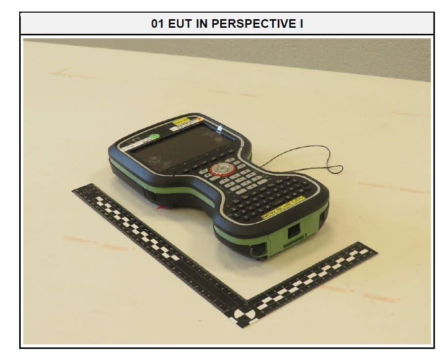
RFD-CSNGP
Jun 27, 2024CS20 Basic
Equipment Class
JAB - Part 15 Class B Digital DeviceRFD-ICG120
Jan 25, 2024iCG120 GNSS Receiver
Equipment Class
DSS - Part 15 Spread Spectrum Transmitter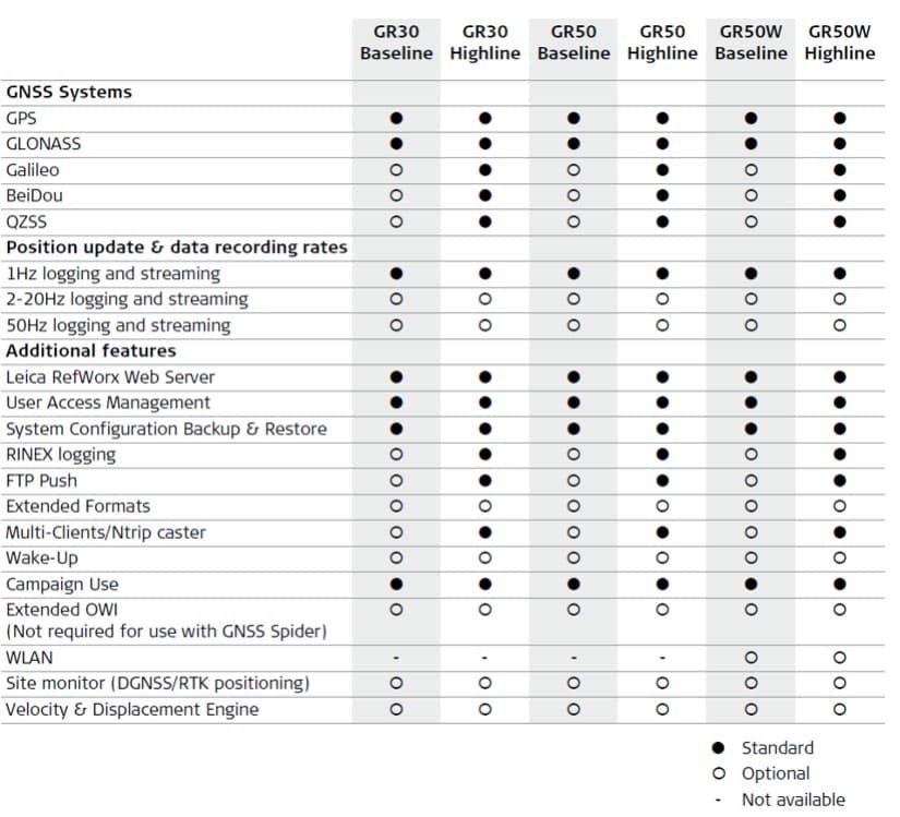
RFD-GR50W
Jan 11, 2024GNSS Reference Server with Wlan
Equipment Class
DTS - Digital Transmission System
RFD-ICG160
Mar 26, 2023iCG160 GNSS Receiver
Equipment Class
DSS - Part 15 Spread Spectrum Transmitter