RFD-PANMOD1PANMOD
Leica Geosystems AG
Click to zoom
Application Details
- Equipment Class
- DSS - Part 15 Spread Spectrum Transmitter
- Date of Grant
- Nov 21, 2005
- Application Purpose
- Original Equipment
- Date of Application
- Nov 21, 2005
- Equipment Note
- PANMOD
- Frequency Range
- 2402.00000000 - 2480.00000000
- Company
- Leica Geosystems AG
- Country
- Switzerland
Documents & Files
Document Text
Text extracted from the exhibit documents filed with the FCC. Open a document above to read the original.
Users Manual
18. Nov 2005 I:\GPS\Charon\Hardware\Bluetooth\PANMOD\General Doku\USERS GUIDE PANMOD for FCC.doc 1 / 5 Leica Geosystems AG USERS GUIDE PANMOD for FCC Project Charon Document: USERS GUIDE PANMOD for FCC.doc Template: Pluto.dot RJ-4139 Version: 1.0 18. Nov 2005 List of contents 1 Description.............................................................................................................2 2 General PANMOD configuration............................................................................2 2.1 PANMOD Connector..............................................................................................2 2.2 UART - USB...........................................................................................................2 2.3 HCI WakeUp Bluetooth..........................................................................................3 2.4 HCI Base Band activ / Stollmann-SPP DCD...........................................................3 2.5 Antenna Type and Matching Network.....................................................................3 2.6 LED’s.....................................................................................................................3 3 PANMOD V3 configuration....................................................................................4 3.1 Picture....................................................................................................................4 3.2 Component Placement...........................................................................................4 4 FCC Compliance.....................................................................................................5 4.1 Labeling Requirements for End Product.................................................................5 4.2 RF-exposure Statement.........................................................................................5 USERS GUIDE PANMOD for FCC Description 18. Nov 2005 2 / 5 1 Description The PANMOD is a Bluetooth Modul based on the Class 2, Panasonic Bluetooth prequallified Standard modul PAN1440. General PANMOD Features : • Single 3.3V +/-5% input voltage • -25°C to +85°C operating and -40°C to +85°C storage temperature range • Various Software Interfaces are available : HCI, Stollmann AT, Zerial AT • Based on Bluetooth V1.2 prequallified Class 2 PAN1440 Bluetooth modul Bluetooth ID : B01839 • HW configurable RS232 or USB 2.0 Interface • RS232 with UART level (3.3V) • HW configurable for internel or externel (U.FL connector) antenna • PI-Pad antenna matching network to adapt the internel antenna to different surroundings • 10 pin FCC zero force connector 2 General PANMOD configuration 2.1 PANMOD Connector CON1 Pin Signal Type Remark 1 CTS IN valid only in RS232 mode 2 RXD USB+ IN USB RS232 mode USB mode 3 TXD USB+ OUT USB RS232 mode USB mode 4 RTS OUT valid only in RS232 mode 5 RESET- IN low activ, t activ > 5ms 6 BBACTIV DCD GPIO15 OUT OUT I/O H : Baseband activity (HCI) DCD with Stollmann SPP TBD 7 WAKEUPHOST OUT HCI : Wake up Host 8 WAKEUPBT GPIO03 IN I/O HCI : Wake up Bluetooth in RS232 mode TBD 9 VCC IN 3.3V +/- 5% 10 GND - Ground 2.2 UART - USB With HCI software the hardware interface can be configured for USB or RS232 mode. With non HCI Software only RS232 mode is possible. Part RS232 mode HCI mode Remark R2 open 1k0O USB mode R5 open 1k5O USB mode R7 1K0O open RS232 mode R13 0O open connect RXD to CON1 Pin 2 R14 0O open connect TXD to CON1 Pin 3 R15 open 0O connect USB+ to CON1 Pin 2 R16 open 0O connect USB- to CON1 Pin 3 bold : settings for PANMOD V3 USERS GUIDE PANMOD for FCC General PANMOD configuration 18. Nov 2005 3 / 5 2.3 HCI WakeUp Bluetooth When in HCI mode and the deep sleep mode is enabled this signal can be used to wake up the Bluetooth from deep sleep mode before sending data to the UART interface. To have the ability to define both initial state R9 and R10 are given. 2.4 HCI Base Band activ / Stollmann-SPP DCD Part Stollmann SPP DCD HCI Remark R3 open 0O GPIO_4 to CON1 Pin 6 R11 0O open GPIO_15 to CON1 Pin 6 bold : settings for PANMOD V3 2.5 Antenna Type and Matching Network To select internel or externel antenna use see table below. Part Int. Antenna Ext. Antenna Remark C3 0.5pF open Pi-Pad : value for Charon C4 10pF open Pi-Pad : value for Charon C5 1.5nH open Pi-Pad : value for Charon ANT1 set open Internel antenna C6 open 2pF U.FL selector U.FL open set U.FL connector bold : settings for PANMOD V3 2.6 LED’s LED1 shows when lighting the running state of the ARM7 processor. LED2 shows in HCI mode the state of the base band activity. USERS GUIDE PANMOD for FCC PANMOD V3 configuration 18. Nov 2005 4 / 5 3 PANMOD V3 configuration • HCI Software Interface • RS232 HW Interface with TXD, RXD, RTS, CTS • HCI Base Band activity om CON1 Pin 6 • Internel antenna with matching network • No LED`s are populatet 3.1 Picture Bottom Top 3.2 Component Placement Bottom Top 18. Nov 2005 I:\GPS\Charon\Hardware\Bluetooth\PANMOD\General Doku\USERS GUIDE PANMOD for FCC.doc 5 / 5 4 FCC Compliance This device complies with Part 15 of the FCC Rules. Operation is subject to the following two conditions: (1) this device may not cause harmful interference, and (2) this device must accept any interference received, including interference that may cause undesired operation. 4.1 Labeling Requirements for End Product The PANMOD is labled with it’s own FCC ID number RFD-PANMOD1. For the end product which contains the PANMOD V3 there must be a lable containing, at least the following information : This device contains FCC ID: RFD-PANMOD1 The label must be affixed on an exterior surface of the end product such that it will be visible upon inspection in compliance with the modular approval guidelines developed by the FCC. In addition, the user manual for the end product must contain the following information: This device complies with Part 15 of the FCC Rules. Operation is subject to the following two conditions: (1) this device may not cause har…
Text truncated - open the document above for the full version.
Cover Letter(s)
Direct: Phone +41 71 727 3894, Fax +41 71 726 5894 / Central: Phone +41 71 727 3131 Internet: [email protected] 060059QM.doc November 14, 2005 Federal Communications Commission Equipment Authorization Branch 7435 Oakland Mills Road Columbia, MD 21046 Request for Confidentiality Leica Geosystems AG - FCC ID: RFD-PANMOD1, FCC Part 15 Certification Gentlemen, In accordance with 0.459 of CFR 47, Leica Geosystems AG hereby requests confidentiality of - Block Diagrams (BlkDia.pdf) - Circuit Diagrams (Schem.pdf) - Parts List (PartsLst.pdf) - Operational Descriptio n (OpDes.pdf) attachments for the subject application. These documents contain detailed system and equipment description and related information about the product which Leica Geosystems AG considers to be proprietary, confidential and a custom design and otherwise would not release to the general public. Since the design is a basis from which future technological products will evolve, Leica Geosystems AG considers that this information would be of benefit to its competitors and that the disclosure of the information in these documents would give competitors an unfair advantage in the market. Sincerely, Gerhard Schwärzler Director Quality Management, Division S&E Leica Geosystems AG Leica Geosystems AG Heinrich-Wild-Strasse CH-9435 Heerbrugg (Switzerland) www.leica-geosystems.com
Cover Letter(s)
Direct: Phone +41 71 727 3894, Fax +41 71 726 5894 / Central: Phone +41 71 727 3131 Internet: [email protected] 060057QM.doc November 22, 2005 FCC Federal Communications Commission Equipment Approvel Services Post Office Box 358315 Pittsburg, PA 15262-0001 Application for a modular approval - FCC ID: RFD-PANMOD1 Dear Application Examiner, We kindly apply for FCC autorization as a modular transmitter for our Bluetooth module PANMOD. The requirements of the FCC Public notice DA00-1407 are met. The following requirements are fulfilled: 1. The modular transmitter must have its own RF shielding. The transmitter portion of the modul is entirely part of the system on chip (SoC) ZV4002 from Broadcom (formerly Zeevo), which has an integrated RF shielding on the SoC. The chip is built as a flip chip on LTCC ground plane construction, which acts as the RF shielding. This means the RF shielding is part of the design of the chip itself. 2. The modular transmitter must have bufferd modulation / data inputs. All modulation and data inputs are buffered. The data inputs to the modular transmitter are first buffered by the UART and second by the on chip processor. The Processor takes the data from the UART-buffer and feeds it to the modulator of the RF part. 3. The modular transmitter must have its own power supply regulation. The modul has its own onboard power supply circuitry. The SoC ZV4002 from Broadcom (formerly Zeevo) is built in a 0.18μm RFCMOS process and integrates all parts of the module on one single silicon chip except Flash, Quarz and Antenna. On chip low drop out voltage regulators bring the external supply voltage from 3.3V +/-5% down to 1.8V for the internal radio and baseband. 4. The modular transmitter must comply with the antenna requirements of Section 15.203 and 15.204c. The transmitter has a built in, permantently attached antenna which is not removeable. 5. The modular transmitter must be tested in a stand-alone configuration. The EUT was tested in the requested stand-alone configuration. Refer to the detailed test report. 6. The modular transmitter must be labled with its own FCC ID number. The EUT is labled with its own FCC ID number. If the module is inside of an end Leica Geosystems AG Heinrich-Wild-Strasse CH-9435 Heerbrugg (Switzerland) www.leica-geosystems.com Direct: Phone +41 71 727 3894, Fax +41 71 726 5894 / Central: Phone +41 71 727 3131 Internet: [email protected] 060057QM.doc product, the label will not be visible. In this case the end product will be labled exterior with the FCC ID. 7. The modular transmitter must comply with any specific rule or operating requirements applicable to the transmitter and the manufacturer must provide adequate instructions along with the module to explain any such requirements. The EUT is compliant with all applicable FCC rules. Detail instructions are given in the USERS GUIDE PANMOD. 8. The modular transmitter must comply with any applicable RF exposure requirements. The antenna shown in this filing must not be co-located or operated in conjunction with any other antenna or transmitter. End users may not be provided with the module installation instructions. OEM integrators and end users must be provided with transmitter operating conditions for satisfying RF exposure compliance. For portable applications OEM integrators need no SAR evaluation. The max source- based time-averaged output of 1.17 mW is below the low threshold of 24mW for d < 2.5 cm. Please contact us if you have any additional questions. Best Regards Gerhard Schwärzler Director Quality Management, Division S&E Leica Geosystems AG
External Photos
ELECTRONIC TECHNOLOGY SYSTEMS DR.GENZ GMBH ETS Dr. Genz GmbH, Germany Registration number: G0M20509-9856-P-15 Page 1 of 5 Appendix A. Pictures ELECTRONIC TECHNOLOGY SYSTEMS DR.GENZ GMBH ETS Dr. Genz GmbH, Germany Registration number: G0M20509-9856-P-15 Page 2 of 5
Internal Photos
ELECTRONIC TECHNOLOGY SYSTEMS DR.GENZ GMBH ETS Dr. Genz GmbH, Germany Registration number: G0M20509-9856-P-15 Page 1 of 4 Appendix A. Pictures ELECTRONIC TECHNOLOGY SYSTEMS DR.GENZ GMBH ETS Dr. Genz GmbH, Germany Registration number: G0M20509-9856-P-15 Page 2 of 4
Operational Description
LW T ab c Inches0.374 ± .0080.079 ± .0080.047 + .004/ -.0080.053 ± .008 0.043 ± .0040.010 ± .004 mm9.5 ± 0.2 2.0 ± 0.21.2 + 0.1/- 0.21.35 ± 0.21.1 ± 0.10.25 ± 0.1 Terminal Configuration 1INPUT 2NC Mechanical Dimensions “High Frequency Ceramic Solutions” 931 Via Alondra • Camarillo, CA 93012 • TEL 805.389.1166 FAX 805.389.1821 www.johanson technology.com 931 Via Alondra • Camarillo, CA 93012 • TEL 805.389.1166 FAX 805.389.1821 Input PowerImpedanceOperating Temperature RangeReel Qty 3 Watts max50 Ω-40 to +85°C1000 Part FrequencyPeak GainAve. GainReturn Number(MHz)(XZ-V)(XZ-V)Loss 2450AT45A100_2400 - 25003.0 dBi typ.1.0 dBi typ. 9.5 dB min. 2.45 GHz Chip AntennaP/N 2450AT45A100 Detail Specification Page 1 of 3 Johanson Technology, Inc. reserves the right to make design changes without notice. All sales are subject to Johanson Technology, Inc. terms and conditions. Mounting Considerations Mount these devices with brown colored side facing up. Line width should be designed to provide 50Ωimpedance matching characteristics. a) Without Matching Circuit (moderate bandwidth)b) With Matching Circuit* (wide bandwidth) *Matching circuit and component values will depend on PCB layout. “High Frequency Ceramic Solutions” www.johanson technology.com 931 Via Alondra • Camarillo, CA 93012 • TEL 805.389.1166 FAX 805.389.1821 2.45 GHz Chip AntennaP/N 2450AT45A100 Detail Specification Page 2 of 3 Test Board for Electrical Characteristic Measurements Typical Return Loss for P/N 2450AT45A100 a) Without Matching Circuitb) With Matching Circuit “High Frequency Ceramic Solutions” www.johanson technology.com 931 Via Alondra • Camarillo, CA 93012 • TEL 805.389.1166 FAX 805.389.1821 2.45 GHz Chip AntennaP/N 2450AT45A100 Detail Specification Page 3 of 3 Typical Radiation Patterns for P/N 2450AT45A100
RF Exposure Info
___________________________________________________________________________________ ETS Handelsregister: Bankverbindung: Electronic Technology Systems Dr. Genz GmbH Amtsgericht Frankfurt/Oder HRB 5151 Sparkasse Oder-Spree Storkower Strasse 38c Geschäftsführung: Dr. Dietmar Genz BLZ 170 550 50 D-15526 Reichenwalde b. Berlin Norbert Kaspar Kto. Nr. 3105165974 ELECTRONIC TECHNOLOGY SYSTEMS DR.GENZ GMBH RF Exposure Calculation Applicant: Leica Geosystems AG FCC ID: RFD-PANMOD1 The antenna shown in this filing must not be co-located or operated in conjunction with any other antenna or transmitter. End users may not be provided with the module installation instructions. OEM integrators and end users must be provided with transmitter operating conditions for satisfying RF exposure compliance.. This kind of equipment is below 60/frequency[GHz] mW(TCB Exclusion List). The Following calculation is the reference data for 20cm – minimum distance. integral Antenna requirement § 15.203). An intentional radiator shall be designed to ensure that no antenna other than that furnished by the responsible party shall be used with the device. The use of a permanently attached antenna or of an antenna that uses a unique coupling to the intentional radiator shall be considered sufficient to comply with the provisions of this section. The manufacturer may design the unit so that a broken antenna can be replaced by the user, but the use of a standard antenna jack or electrical connector is prohibited.
Test Report
ELECTRONIC TECHNOLOGY SYSTEMS DR. GENZ GMBH TEST - REPORT FCC RULES PART 15 / SUBPART C FCC ID: RFD-PANMOD1 Test report no.: G0M20509-9856-P-15 Certificate 1983-01 ELECTRONIC TECHNOLOGY SYSTEMS STORKOWER STRASSE 38C, D-15526 REICHENWALDE B. BERLIN DR. GENZ GMBH PHONE +49-33631-888 00 FAX +49-33631-888 660 ETS Dr. Genz GmbH, Germany Registration number: G0M20509-9856-P-15 Page 1 of 35 ELECTRONIC TECHNOLOGY SYSTEMS DR.GENZ GMBH TABLE OF CONTENTS 1 General information 1.1 Notes 1.2 Testing laboratory 1.3 Details of approval holder 1.4 Application details 1.5 Test item 1.6 Test standards 2 Technical test 2.1 Summary of test results 2.2 Test environment 2.3 Test equipment utilized 2.4 General Test Procedure 3 Test Results 3.1 Peak output power 3.2 Equivalent isotropic radiated power 3.3 RF exposure radiated emission 3.4 Antenna requirement 3.5 Out of band radiated emission 3.6 Transmitter radiated emissions in restricted bands 3.7 Spurious emissions (tx) 3.8 Carrier frequency separation 3.9 Number of hopping frequency 3.10 Time of occupancy 3.11 20 dB bandwidth 3.12 Band-edge compliance of RF emissions 3.13 Conducted measurement at (AC) power line ETS Dr. Genz GmbH, Germany Registration number: G0M20509-9856-P-15 Page 2 of 35 ELECTRONIC TECHNOLOGY SYSTEMS DR.GENZ GMBH 1 General Information 1.1 Notes The purpose of conformity testing is to increase the probability of adherence to the essential requirements or conformity specifications, as appropriate. The complexity of the technical specifications, however, means that full and thorough testing is impractical for both technical and economic reasons. Furthermore, there is no guarantee that a test sample which has Passed all the relevant tests conforms to a specification. Neither is there any guarantee that such a test sample will interwork with other genuinely open systems. The existence of the tests nevertheless provides the confidence that the test sample possesses the qualities as maintained and that is performance generally conforms to representative cases of communications equipment. The test results of this test report relate exclusively to the item tested as specified in 1.5. The test report may only be reproduced or published in full. Reproduction or publication of extracts from the report requires the prior written approval of the ELECTRONIC TECHNOLOGY SYSTEMS DR. GENZ GMBH. Tester: 17.10.2005 D. Hoppe Date ETS-Lab. Name Signature Technical responsibility for area of testing: 17.10.2005 N. Kaspar Date ETS Name Signature ETS Dr. Genz GmbH, Germany Registration number: G0M20509-9856-P-15 Page 3 of 35 ELECTRONIC TECHNOLOGY SYSTEMS DR.GENZ GMBH 1.2 Testing laboratory 1.2.1 Location ELECTRONIC TECHNOLOGY SYSTEM DR. GENZ GMBH (ETS) Storkower Straße 38c D-15526 Reichenwalde b. Berlin Germany Telefon : +49 33631 888 00 Telefax : +49 33631 888 66 1.2.2 Details of accreditation status A CCREDITED TESTING LABORATORY DAR-REGISTRATION NUMBER: TTI-P-G 126/96 ACCREDITED COMPETENT BODY DAR- REGISTRATION NUMBER: BPT-ZE-026/96 FCC FILED TEST LABORATORY REG. NO. 96970 BLUETOOTH QUALIFICATION TEST FACILITY (BQTF) A CCREDITED BY BLUETOOTH QUALIFICATION REVIEW BOARD INDUSTRY CANADA FILED TEST LABORATORY REG. NO. IC 3470 A2LA ACCREDITED Certificate Number 1983-01 1.3 Details of approval holder Name : Leica Geosystems AG Street : Heinrich Wild Strasse 1 Town : CH-9435 Heerbrugg Country : Switzerland Telephone : +41 71 727 4139 Fax : +41 71 726 4139 Contact : Herr Jürgen Ruckdeschel E-mail : [email protected] ETS Dr. Genz GmbH, Germany Registration number: G0M20509-9856-P-15 Page 4 of 35 ELECTRONIC TECHNOLOGY SYSTEMS DR.GENZ GMBH 1.4 Application details Date of receipt of application : 27.09.2005 Date of receipt of test item : 27.09.2005 Date of test : 27.09.2005 – 06.10.2005 1.5 Test item Description of test item : PANMOD Type identification : 1i Brand Name: Leica Serial number : without Photos : See Appendix A Technical data Frequency band : 2.4GHz – 2.4835GHz Frequency ( ch A) : 2402 MHz Frequency (ch B) : 2441 MHz Frequency (ch C) : 2480 MHz Transmitter Vnom Vnom Power (ch A) : Conducted: -3.98 dBm Radiated: 1.85 dBm Power (ch B) : Conducted: -5.34 dBm Radiated: -3.33 dBm Power (ch C) : Conducted: -6.96 dBm Radiated: -7.52 dBm Power supply : 3.3 V DC Operating mode : duplex Type of modulation : FHSS Antenna type : 2.45 GHz Chip Antenna Antenna gain : 3.0 dBi (Peak); 1.0 dBi (Average) ETS Dr. Genz GmbH, Germany Registration number: G0M20509-9856-P-15 Page 5 of 35 ELECTRONIC TECHNOLOGY SYSTEMS DR.GENZ GMBH Host device : none Classification : Fixed Device Mobile Device (Human Body distance > 20cm) Portable Device (Human Body distance < 20cm) Manufacturer: (if applicable) Name : Leica Geosystems AG Street : Heinrich Wild Strasse 1 Town : CH-9435 Heerbrugg Country : Switzerland Additional information: The test sample is designed as Bluetooth device. Its pseudorandom hopping scheme, authentication, receiver parameters, synchronization procedure and other parameters are determined by Bluetooth Core Specification. ETS Dr. Genz GmbH, Germany Registration number: G0M20509-9856-P-15 Page 6 of 35 ELECTRONIC TECHNOLOGY SYSTEMS DR.GENZ GMBH 1.6 Test standards Technical standard : FCC RULES PART 15 / SUBPART C § 15.247 2 Technical test 2.1 Summary of test results No deviations from the technical specification(s) were ascertained in the course : of the tests performed. or The deviations as specified in 2.5 were ascertained in the course of the tests performed. 2.2 Test environment Temperature : 25 o C Relative humidity content : 20 ... 75 % Air pressure : 86 ... 103 kPa Details of power supply : 3.3 V DC Extreme conditions parameters: : test voltage - extreme min.: -- V (Vnom – 15%) max: -- V (Vnom + 15%) ETS Dr. Genz GmbH, Germany Registration number: G0M20509-9856-P-15 Page 7 of 35 ELECTRONIC TECHNOLOGY SYSTEMS DR.GENZ GMBH 2.3 Test equipment utilized No. Test equipment Type Manufacturer ETS 0001 ESD Gun SESD 30000 Schlöder ETS 0002 Test receiver…
Text truncated - open the document above for the full version.
Test Setup Photos
ELECTRONIC TECHNOLOGY SYSTEMS DR.GENZ GMBH ETS Dr. Genz GmbH, Germany Registration number: G0M20509-9856-P-15 Page 3 of 5 ELECTRONIC TECHNOLOGY SYSTEMS DR.GENZ GMBH ETS Dr. Genz GmbH, Germany Registration number: G0M20509-9856-P-15 Page 4 of 5 ELECTRONIC TECHNOLOGY SYSTEMS DR.GENZ GMBH ETS Dr. Genz GmbH, Germany Registration number: G0M20509-9856-P-15 Page 5 of 5
Contact Information
Applicant
Hannes Juen(Director Global Quality Management)
Test Firm
Eurofins Product Service GmbHRobert Kschiwan-Kaspar
Technical Specifications
| # | Rule Parts | Frequency Range | Power Output |
|---|---|---|---|
| 1 | 15C | 2.40 GHz - 2.48 GHz | 400.00 µW |
Other Applications from Leica Geosystems AG
RFD-BELUGA
Oct 01, 2025Total Station
Equipment Class
PCB - PCS Licensed Transmitter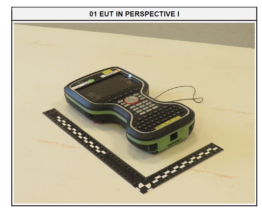
RFD-CSNGP
Jun 27, 2024CS20 Basic
Equipment Class
JAB - Part 15 Class B Digital DeviceRFD-ICG120
Jan 25, 2024iCG120 GNSS Receiver
Equipment Class
DSS - Part 15 Spread Spectrum Transmitter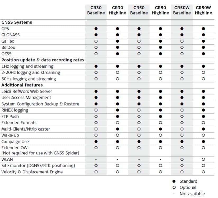
RFD-GR50W
Jan 11, 2024GNSS Reference Server with Wlan
Equipment Class
DTS - Digital Transmission System
RFD-ICG160
Mar 26, 2023iCG160 GNSS Receiver
Equipment Class
DSS - Part 15 Spread Spectrum Transmitter