RFD-ZENO20CGNSS Data Collector
Leica Geosystems AG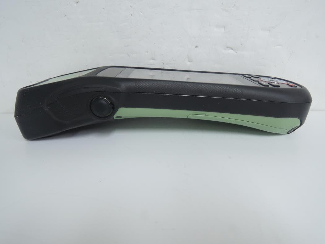
Click to zoom
Application Details
- Equipment Class
- DTS - Digital Transmission System
- Date of Grant
- Aug 31, 2015
- Application Purpose
- Original Equipment
- Date of Application
- Aug 31, 2015
- Equipment Note
- GNSS Data Collector
- Frequency Range
- 2412.00000000 - 2462.00000000
- Company
- Leica Geosystems AG
- Country
- Switzerland
Documents & Files
Document Text
Text extracted from the exhibit documents filed with the FCC. Open a document above to read the original.
Users Manual
Leica Zeno 20 Android User Manual Version 1.1 English Zeno 20 Android, Introduction 2 Introduction PurchaseCongratulations on the purchase of a Leica Zeno 20. This manual contains important safety directions as well as instructions for setting up the product and operating it. Refer to "1 Safety Directions" for further information. Read carefully through the User Manual before you switch on the product. Product Identifica- tion The type and serial number of your product are indicated on the type plate. Always refer to this information when you need to contact your agency or Leica Geosystems authorised service workshop. Trademarks and Licenses • The operating system is using the Android Open Source Project (AOSP). The license associated with it is available at https://source.android.com/source/licenses.html#android-open-source-project- license. • CompactFlash and CF are trademarks of SanDisk Corporation • Bluetooth ® is a registered trademark of Bluetooth SIG, Inc. • SD Logo is a trademark of SD-3C, LLC. All other trademarks are the property of their respective owners. Validity of this manual This manual applies to the Android version of the Leica Zeno 20 device. Available documentation * only available as Online Help Refer to the following resources for all Zeno 20 documentation/software: • the Leica USB documentation card • https://myworld.leica-geosystems.com NameDescription/Format Leica Zeno 20 Quick Guide Provides an overview of the product together with tech- nical data and safety directions. Intended as a quick reference guide. Leica Zeno 20 User Manual All instructions required in order to operate the product to a basic level are contained in the User Manual. Provides an overview of the product together with tech- nical data and safety directions. - NameDescription/Format Zeno GIS Getting Started Guide Describes the general working of the product in standard use. Intended as a quick reference field guide. - Zeno Connect Getting Started Guide Describes the general working of the product in standard use. Intended as a quick reference field guide. - Zeno Mobile Quick Guide Describes the general working of the product in standard use. Intended as a quick reference field guide. - Zeno GIS Help * Overall comprehensive help to the product and applica- tion functions. Included are detailed descriptions of special software/hardware settings and software/hard- ware functions. -- Zeno 20 Android, Introduction 3 myWorld@Leica Geosystems (https://myworld.leica-geosystems.com) offers a wide range of services, information and training material. With direct access to myWorld, you are able to access all relevant services whenever it is convenient for you, 24 hours a day, 7 days per week. This increases your efficiency and keeps you and your equipment instantly updated with the latest information from Leica Geosystems. ServiceDescription myProductsAdd all Leica Geosystems products that you and your company own. View detailed information on your products, buy additional options or Customer Care Packages (CCPs), update your prod- ucts with the latest software and keep up-to-date with the latest documentation. myServiceView the service history of your products in Leica Geosystems Service Centres and detailed information on the services performed on your products. For your products that are currently in Leica Geosystems Service Centres view the current service status and the expected end date of service. mySupportCreate new support requests for your products that will be answered by your local Leica Geosystems Support Team. View the complete history of your Support and view detailed informa- tion on each request in case you want to refer to previous support requests. myTrainingEnhance your product knowledge with the Leica Geosystems Campus - Information, Knowledge, Training. Study the latest online training material or download training material on your products. Keep up-to-date with the latest News on your prod- ucts and register for Seminars or Courses in your country. myTrustedServices Offers increased productivity while at the same time providing maximum security. • myExchange With myExchange you can exchange any files/objects from your computer to any of your Leica Exchange Contacts. • mySecurity If your instrument is ever stolen, a locking mechanism is avail- able to ensure that the instrument is disabled and can no longer be used. Zeno 20 Android, Table of Contents 4 Table of Contents In this manualChapterPage 1Safety Directions 6 1.1General Introduction6 1.2Definition of Use7 1.3Limits of Use7 1.4Responsibilities8 1.5Hazards of Use8 1.6Electromagnetic Compatibility EMC10 1.7FCC Statement, Applicable in U.S.12 1.8ICES-003 Statement, Applicable in Canada13 2Description of the System 14 2.1Overview14 2.2System Concept15 2.2.1Software Concept15 2.2.2Power Concept15 2.2.3Data Storage Concept16 2.3System Components16 2.4Zeno 20 Components17 3User Interface 18 3.1Keyboard18 3.2Operating Principles19 3.3LED Indicators on Zeno 2020 4Operation 21 4.1Equipment Setup21 4.1.1Fixing the Display Foil to the Zeno 2021 4.1.2Inserting and Removing a SIM Card and SD Card21 4.1.3Attaching the AS10/AS05 Antenna to the Zeno 2023 4.2Batteries23 4.2.1Operating Principles23 4.2.2Changing the Battery24 4.2.3Charging the Battery25 4.3Power Functions26 4.4Connecting the Zeno 20 to a PC with the Micro-USB Cable27 4.5Optimising the Zeno 20 for GNSS Tracking27 4.6Setting up the Zeno 20 with a Disto S91028 5Software 29 5.1Overview: Home Screen, Navigation, Apps and Widgets29 5.2Settings32 5.2.1Changing the Operating System Language33 5.2.2Resetting the Zeno 20 Device33 5.3Useful Applications34 5.3.1Hot Keys34 5.3.2Screenshots35 5.3.3File Manager35 5.3.4System Information35 5.3.5Using the Digital Camera35 5.3.6Boot Logo Changer36 Zeno 20 Android, Table of Contents 5 6Care and Transport 37 6.1Transport37 6.2Storage37 6.3Cleaning and Drying38 7Technical Data 39 7.1Zeno 20 Technical Data39 7.2Conformity to National Regulati…
Text truncated - open the document above for the full version.
Cover Letter(s)
DT&C Co., Ltd. 42, Yurim-ro, 154beon-gil, Cheoin-gu, Yongin-si, Gyeonggi-do, Korea 449-935 Date: June 08, 2015 UL Verification Services Inc. 47173 Benicia Street Fremont, CA 94538, USA To whom it may concern: I, the undersigned, hereby authorize UL Verification Services Inc. to act on our behalf in all manners relating to application for equipment authorization, including signing of all documents relating to these matters. Any and all acts carried out by UL Verification Services Inc. on our behalf shall have the same effect as acts of our own. I, the undersigned, hereby certify that we are not subject to a denial of federal benefits, that includes FCC benefits, pursuant to Section 5301 of the Anti-Drug Abuse Act of 1988, 21 U.S.C. 853(a). In authorizing UL Verification Services Inc. as our agent, we still recognize that we are responsible to: a) comply with the relevant provisions of the certification program; b) make all necessary arrangements for the conduct of the evaluation, including provision for examining documentation and access to all areas, records (including internal audit reports) and personnel for the purposes of evaluation (e.g. testing, inspection, assessment, surveillance, reassessment) and resolution of complaints; c) make claims regarding certification only in respect of the scope for which certification has been granted; d) do not use our product certification in such a manner as to bring the Certification Division into disrepute and not make any statement regarding our product certification which the Certification Division may consider misleading or unauthorized; e) upon suspension or cancellation of certification, discontinue use of all advertising matter that contains any reference thereto and return any certification documents as required by the Certification Division; f) use certification only to indicate the products are certified as being in conformity with specified standards; g) endeavor to ensure that no certificate or report nor any part thereof is used in a misleading manner; DT&C Co., Ltd. 42, Yurim-ro, 154beon-gil, Cheoin-gu, Yongin-si, Gyeonggi-do, Korea 449-935 h) ensure that any reference to our product certification in communication media such as documents, brochures or advertising, complies with the requirements of the Certification Division; i) keep a record of all complaints made known to the us relating to the product’s compliance with requirements of the relevant standard and to make these records available to the Certification Division when requested; j) take appropriate action with respect to such complaints and any deficiencies found in products or services that affect compliance with the requirements for certification; k) document the actions taken. This authorization is valid until further written notice from the applicant. Sincerely Yours, Harvey Sung Director REMARK: 1. This authorization letter will be sent along with your application when filing with UL Verification Services Inc. 2. Please follow the format and type it on company letterhead and send original to us. 3. Authorized signature must be in agreement with grantee code contact in FCC database and Industry Canada contact information.
Cover Letter(s)
Leica Geosystems AG Heinrich-Wild-Strasse Heerbrugg CH-9435 Switzerland Date: June 8, 2015 Attestation Letter for FCC ID: RFD-ZENO20C To whom it may concern: We hereby declare that The Leica Geosystems AG product Zeno 20 (FCC ID: RFD-ZENO20C) in the RF module (WG7351) does not use 5GHz band by software. Best regards, Sincerely, Hannes Juen Quality Management Leica Geosystems AG
External Photos
FCC ID: RFD-ZENO20C Copyright Ⓒ 2015, DT&C Co., Ltd. View 1 FCC ID: RFD-ZENO20C Copyright Ⓒ 2015, DT&C Co., Ltd. View 2 FCC ID: RFD-ZENO20C Copyright Ⓒ 2015, DT&C Co., Ltd. View 3
ID Label/Location Info
FCC ID: RFD-ZENO20G IC: 3177A-ZENO20G Copyright Ⓒ 2015, DT&C Co., Ltd. FCC ID SAMPLE LABEL & LOCATION LABELLING REQUIREMENTS PER §2.925 The Label shown shall be permanently affixed at a conspicuous location on the device and be readily visible to the user at the time of purchase - The FCC label shown is representative of the label that will appear on the radio when in production. Other information may also be included on this label. - The device is so small that it is not practicable to place the statement specified under 15.19 statement request, the information required by this paragraph shall be placed in a prominent location in the user's manual.
Internal Photos
FCC ID: RFD-ZENO20C Copyright Ⓒ 2015, DT&C Co., Ltd. View 1 FCC ID: RFD-ZENO20C Copyright Ⓒ 2015, DT&C Co., Ltd. View 2 FCC ID: RFD-ZENO20C Copyright Ⓒ 2015, DT&C Co., Ltd. View 3 FCC ID: RFD-ZENO20C Copyright Ⓒ 2015, DT&C Co., Ltd. View 4 FCC ID: RFD-ZENO20C Copyright Ⓒ 2015, DT&C Co., Ltd. View 5 FCC ID: RFD-ZENO20C Copyright Ⓒ 2015, DT&C Co., Ltd. View 6 FCC ID: RFD-ZENO20C Copyright Ⓒ 2015, DT&C Co., Ltd. View 7 FCC ID: RFD-ZENO20C Copyright Ⓒ 2015, DT&C Co., Ltd. View 8 FCC ID: RFD-ZENO20C Copyright Ⓒ 2015, DT&C Co., Ltd. View 9 FCC ID: RFD-ZENO20C Copyright Ⓒ 2015, DT&C Co., Ltd. View 10 FCC ID: RFD-ZENO20C Copyright Ⓒ 2015, DT&C Co., Ltd. View 11 FCC ID: RFD-ZENO20C Copyright Ⓒ 2015, DT&C Co., Ltd. View 12 FCC ID: RFD-ZENO20C Copyright Ⓒ 2015, DT&C Co., Ltd. View 13 FCC ID: RFD-ZENO20C Copyright Ⓒ 2015, DT&C Co., Ltd. View 14 FCC ID: RFD-ZENO20C Copyright Ⓒ 2015, DT&C Co., Ltd. View 15 Antenna_GPS Antenna_GSM FCC ID: RFD-ZENO20C Copyright Ⓒ 2015, DT&C Co., Ltd. View 16 Antenna_WLAN
RF Exposure Info
Report No.: DRRFCC1505-0039(2) FCC ID: RFD-ZENO20C Date of issue: Aug. 25, 2015 TRF-RF-601(00)120709 Page2 / 80 Copyright Ⓒ 2015, DT&C Co., Ltd. Table of Contents 1. DESCRIPTION OF DEVICE .......................................................................................................... 5 1.1 Guidance Applied ................................................................................................................... 6 1.2 Device Overview .................................................................................................................... 6 1.3 Nominal and Maximum Output Power Specifications ............................................................ 6 1.4 DUT Antenna Locations ......................................................................................................... 7 1.5 Determination of the SAR Test Configuration ........................................................................ 8 1.6 SAR Test Exclusions Applied ................................................................................................. 9 1.7 Power Reduction for SAR .................................................................................................... 10 1.8 Device Serial Numbers ........................................................................................................ 10 2. INTROCUCTION ......................................................................................................................... 11 3. DESCRIPTION OF TEST EQUIPMENT ..................................................................................... 12 3.1 SAR MEASUREMENT SETUP ............................................................................................ 12 3.2 EX3DV4 Probe Specification ............................................................................................... 13 3.3 Probe Calibration Process ................................................................................................... 14 3.3.1 E-Probe Calibration ......................................................................................................... 14 3.4 Data Extrapolation ................................................................................................................ 15 3.5 ELI PHANTOM ..................................................................................................................... 16 3.6 Device Holder for Transmitters ............................................................................................ 16 3.7 Brain & Muscle Simulation Mixture Characterization ........................................................... 17 3.8 SAR TEST EQUIPMENT ..................................................................................................... 18 4. TEST SYSTEM SPECIFICATIONS ............................................................................................. 19 5. SAR MEASUREMENT PROCEDURE ........................................................................................ 20 5.1 Measurement Procedure ...................................................................................................... 20 6. TEST CONFIGURATION POSITIONS FOR HANDSETS .......................................................... 21 6.1 Device Holder ....................................................................................................................... 21 6.2 Head Exposure Configurations ............................................................................................ 21 6.3 Extremity Exposure Configurations ...................................................................................... 21 7. RF EXPOSURE LIMITS .............................................................................................................. 22 8. FCC MEASUREMENT PROCEDURES...................................................................................... 23 8.1 Measured and Reported SAR .............................................................................................. 23 8.2 Procedures Used to Establish RF Signal for SAR ............................................................... 23 8.3 SAR Measurement Conditions for CDMA2000 .................................................................... 23 8.3.1 Output Power Verification ................................................................................................ 23 8.3.2 CDMA 2000 1x Advanced ............................................................................................... 24 8.4 SAR Testing with 802.11 Transmitters ................................................................................ 24 8.4.1 General Device Setup ..................................................................................................... 24 8.4.2 Initial Test Position Procedure ......................................................................................... 24 8.4.3 2.4 GHz SAR Test Requirements .................................................................................... 25 8.4.4 OFDM Transmission Mode and SAR Test Channel Selection ........................................ 25 8.4.5 Initial Test Configuration Procedure ................................................................................ 25 8.4.6 Subsequent Test Configuration Procedures .................................................................... 25 9. RF CONDUCTED POWERS ....................................................................................................... 26 9.1 CDMA Conducted Powers ................................................................................................... 26 9.2 WLAN Conducted Powers ................................................................................................... 27 9.3 Bluetooth Conducted Powers............................................................................................... 28 10. SYSTEM VERIFICATION .......................................................…
Text truncated - open the document above for the full version.
RF Exposure Info
Report No.: DRRFCC1505-0039(2) FCC ID: RFD-ZENO20C Date of issue: Aug. 25, 2015 TRF-RF-601(00)120709 Page54 / 80 Copyright Ⓒ 2015, DT&C Co., Ltd. Attachment 2. – Dipole Calibration Data Report No.: DRRFCC1505-0039(2) FCC ID: RFD-ZENO20C Date of issue: Aug. 25, 2015 TRF-RF-601(00)120709 Page55 / 80 Copyright Ⓒ 2015, DT&C Co., Ltd. Report No.: DRRFCC1505-0039(2) FCC ID: RFD-ZENO20C Date of issue: Aug. 25, 2015 TRF-RF-601(00)120709 Page56 / 80 Copyright Ⓒ 2015, DT&C Co., Ltd. Report No.: DRRFCC1505-0039(2) FCC ID: RFD-ZENO20C Date of issue: Aug. 25, 2015 TRF-RF-601(00)120709 Page57 / 80 Copyright Ⓒ 2015, DT&C Co., Ltd. Report No.: DRRFCC1505-0039(2) FCC ID: RFD-ZENO20C Date of issue: Aug. 25, 2015 TRF-RF-601(00)120709 Page58 / 80 Copyright Ⓒ 2015, DT&C Co., Ltd. Report No.: DRRFCC1505-0039(2) FCC ID: RFD-ZENO20C Date of issue: Aug. 25, 2015 TRF-RF-601(00)120709 Page59 / 80 Copyright Ⓒ 2015, DT&C Co., Ltd. Report No.: DRRFCC1505-0039(2) FCC ID: RFD-ZENO20C Date of issue: Aug. 25, 2015 TRF-RF-601(00)120709 Page60 / 80 Copyright Ⓒ 2015, DT&C Co., Ltd. Report No.: DRRFCC1505-0039(2) FCC ID: RFD-ZENO20C Date of issue: Aug. 25, 2015 TRF-RF-601(00)120709 Page61 / 80 Copyright Ⓒ 2015, DT&C Co., Ltd. Report No.: DRRFCC1505-0039(2) FCC ID: RFD-ZENO20C Date of issue: Aug. 25, 2015 TRF-RF-601(00)120709 Page62 / 80 Copyright Ⓒ 2015, DT&C Co., Ltd. Report No.: DRRFCC1505-0039(2) FCC ID: RFD-ZENO20C Date of issue: Aug. 25, 2015 TRF-RF-601(00)120709 Page63 / 80 Copyright Ⓒ 2015, DT&C Co., Ltd. Report No.: DRRFCC1505-0039(2) FCC ID: RFD-ZENO20C Date of issue: Aug. 25, 2015 TRF-RF-601(00)120709 Page64 / 80 Copyright Ⓒ 2015, DT&C Co., Ltd. Report No.: DRRFCC1505-0039(2) FCC ID: RFD-ZENO20C Date of issue: Aug. 25, 2015 TRF-RF-601(00)120709 Page65 / 80 Copyright Ⓒ 2015, DT&C Co., Ltd. Report No.: DRRFCC1505-0039(2) FCC ID: RFD-ZENO20C Date of issue: Aug. 25, 2015 TRF-RF-601(00)120709 Page66 / 80 Copyright Ⓒ 2015, DT&C Co., Ltd. Report No.: DRRFCC1505-0039(2) FCC ID: RFD-ZENO20C Date of issue: Aug. 25, 2015 TRF-RF-601(00)120709 Page67 / 80 Copyright Ⓒ 2015, DT&C Co., Ltd. Report No.: DRRFCC1505-0039(2) FCC ID: RFD-ZENO20C Date of issue: Aug. 25, 2015 TRF-RF-601(00)120709 Page68 / 80 Copyright Ⓒ 2015, DT&C Co., Ltd. Report No.: DRRFCC1505-0039(2) FCC ID: RFD-ZENO20C Date of issue: Aug. 25, 2015 TRF-RF-601(00)120709 Page69 / 80 Copyright Ⓒ 2015, DT&C Co., Ltd. Report No.: DRRFCC1505-0039(2) FCC ID: RFD-ZENO20C Date of issue: Aug. 25, 2015 TRF-RF-601(00)120709 Page70 / 80 Copyright Ⓒ 2015, DT&C Co., Ltd. Report No.: DRRFCC1505-0039(2) FCC ID: RFD-ZENO20C Date of issue: Aug. 25, 2015 TRF-RF-601(00)120709 Page71 / 80 Copyright Ⓒ 2015, DT&C Co., Ltd. Report No.: DRRFCC1505-0039(2) FCC ID: RFD-ZENO20C Date of issue: Aug. 25, 2015 TRF-RF-601(00)120709 Page72 / 80 Copyright Ⓒ 2015, DT&C Co., Ltd. Report No.: DRRFCC1505-0039(2) FCC ID: RFD-ZENO20C Date of issue: Aug. 25, 2015 TRF-RF-601(00)120709 Page73 / 80 Copyright Ⓒ 2015, DT&C Co., Ltd. Report No.: DRRFCC1505-0039(2) FCC ID: RFD-ZENO20C Date of issue: Aug. 25, 2015 TRF-RF-601(00)120709 Page74 / 80 Copyright Ⓒ 2015, DT&C Co., Ltd. Report No.: DRRFCC1505-0039(2) FCC ID: RFD-ZENO20C Date of issue: Aug. 25, 2015 TRF-RF-601(00)120709 Page75 / 80 Copyright Ⓒ 2015, DT&C Co., Ltd. Report No.: DRRFCC1505-0039(2) FCC ID: RFD-ZENO20C Date of issue: Aug. 25, 2015 TRF-RF-601(00)120709 Page76 / 80 Copyright Ⓒ 2015, DT&C Co., Ltd. Report No.: DRRFCC1505-0039(2) FCC ID: RFD-ZENO20C Date of issue: Aug. 25, 2015 TRF-RF-601(00)120709 Page77 / 80 Copyright Ⓒ 2015, DT&C Co., Ltd. Report No.: DRRFCC1505-0039(2) FCC ID: RFD-ZENO20C Date of issue: Aug. 25, 2015 TRF-RF-601(00)120709 Page78 / 80 Copyright Ⓒ 2015, DT&C Co., Ltd. Report No.: DRRFCC1505-0039(2) FCC ID: RFD-ZENO20C Date of issue: Aug. 25, 2015 TRF-RF-601(00)120709 Page79 / 80 Copyright Ⓒ 2015, DT&C Co., Ltd. Attachment 3. – SAR SYSTEM VALIDATION Report No.: DRRFCC1505-0039(2) FCC ID: RFD-ZENO20C Date of issue: Aug. 25, 2015 TRF-RF-601(00)120709 Page80 / 80 Copyright Ⓒ 2015, DT&C Co., Ltd. SAR System Validation Per FCC KDB 865664 D02v01r01, SAR system validation status should be documented to confirm measurement accuracy. The SAR systems (including SAR probes, system components and software versions) used for this device were validated against its performance specifications prior to the SAR measurements. Reference dipoles were used with the required tissue- equivalent media for system validation, according to the procedures outlined in FCC KDB 865664 D01v01r03 and IEEE 1528-2013. Since SAR probe calibrations are frequency dependent, each probe calibration point was validated at a frequency within the valid frequency range of the probe calibration point, using the system that normally operates with the probe for routine SAR measurements and according to the required tissue-equivalent media. A tabulated summary of the system validation status including the validation date(s), measurement frequencies, SAR probes and tissue dielectric parameters has been included. Table Attachment 3.1 SAR System Validation Summary SAR System Freq. [MHz] Date Probe SN Probe Type Probe CAL. Point PERM. COND. CW Validation MOD. Validation (εr) (σ) Sensi- tivity Probe Linearity Probe Isortopy MOD. Type Duty Factor PAR D 835 2014-10-02 3933 EX3DV4 835 Head 40.308 0.890 PASS PASS PASS GMSK PASS N/A D 1900 2014-10-03 3933 EX3DV4 1900 Head 40.650 1.416 PASS PASS PASS GMSK PASS N/A D 2450 2014-10-06 3933 EX3DV4 2450 Head 40.313 1.832 PASS PASS PASS OFDM N/A PASS D 835 2014-10-02 3933 EX3DV4 835 Body 53.451 0.991 PASS PASS PASS GMSK PASS N/A D 1900 2014-10-03 3933 EX3DV4 1900 Body 52.240 1.532 PASS PASS PASS GMSK PASS N/A D 2450 2014-10-06 3933 EX3DV4 2450 Body 51.349 1.988 PASS PASS PASS OFDM N/A PASS NOTE: While the probes have been calibrated for both a CW and modulated signals, all measurements were performed using communication systems calibrated for CW signals only. Modulations in the table above represent test configurations for which the measurement syst…
Text truncated - open the document above for the full version.
RF Exposure Info
Report No.: DRRFCC1505-0039(2) FCC ID: RFD-ZENO20C Date of issue: Aug. 25, 2015 Copyright Ⓒ 2015, DT&C Co., Ltd. SAR Plots Verification Plots SAR Test Plots DT&C Co., Ltd. DUT: Dipole 835 MHz; Type: D835V2; Serial: D835V2 - SN:4d159 Communication System: CW (0); Frequency: 835 MHz;Duty Cycle: 1:1 Medium parameters used: f = 835 MHz; σ = 1.001 S/m; ε r = 55.554; ρ = 1000 kg/m 3 Phantom section: Flat Section DASY5 Configuration: Probe: EX3DV4 - SN3933; ConvF(10.38, 10.38, 10.38); Calibrated: 9/22/2014; ; Electronics: DAE4 Sn1453 Phantom: ELI v5.0_2013_10_08; Type: QDIVA001BB; Serial: 1223 Measurement SW: DASY52, Version 52.8 (8); SEMCAD X Version 14.6.10 (7331) Test Date: 2015-04-15; Ambient Temp: 21.1; Tissue Temp:21.6 835 MHz System Verification Area Scan (41x121x1): Interpolated grid: dx=15mm, dy=15mm Zoom Scan (7x7x7)/Cube 0: Measurement grid: dx=5mm, dy=5mm, dz=5mm Power Drift = -0.15 dB Peak SAR (extrapolated) = 3.58 W/kg SAR(1 g) = 2.32 W/kg; SAR(10 g) = 1.53 W/kg 0 dB = 2.68 W/kg DT&C Co., Ltd. DUT: Dipole 835 MHz; Type: D835V2; Serial: D835V2 - SN:4d159 Communication System: CW (0); Frequency: 835 MHz;Duty Cycle: 1:1 Medium parameters used: f = 835 MHz; σ = 1.001 S/m; ε r = 55.554; ρ = 1000 kg/m 3 Phantom section: Flat Section DASY5 Configuration: Probe: EX3DV4 - SN3933; ConvF(10.38, 10.38, 10.38); Calibrated: 9/22/2014; ; Electronics: DAE4 Sn1453 Phantom: ELI v5.0_2013_10_08; Type: QDIVA001BB; Serial: 1223 Measurement SW: DASY52, Version 52.8 (8); SEMCAD X Version 14.6.10 (7331) Test Date: 2015-04-15; Ambient Temp: 21.1; Tissue Temp:21.6 835 MHz System Verification Area Scan (41x121x1): Interpolated grid: dx=15mm, dy=15mm Zoom Scan (7x7x7)/Cube 0: Measurement grid: dx=5mm, dy=5mm, dz=5mm Power Drift = -0.15 dB Peak SAR (extrapolated) = 3.58 W/kg SAR(1 g) = 2.32 W/kg; SAR(10 g) = 1.53 W/kg DT&C Co., Ltd. DUT: Dipole 1900 MHz; Type: D1900V2; Serial: D1900V2 - SN:5d176 Communication System: CW (0); Frequency: 1900 MHz;Duty Cycle: 1:1 Medium parameters used: f = 1900 MHz; σ = 1.52 S/m; ε r = 51.835; ρ = 1000 kg/m 3 Phantom section: Flat Section DASY5 Configuration: Probe: EX3DV4 - SN3933; ConvF(8.14, 8.14, 8.14); Calibrated: 9/22/2014; ; Electronics: DAE4 Sn1453 Phantom: ELI v5.0_2013_10_08; Type: QDIVA001BB; Serial: 1223 Measurement SW: DASY52, Version 52.8 (8); SEMCAD X Version 14.6.10 (7331) Test Date: 2015-04-20; Ambient Temp: 21.2; Tissue Temp:21.8 1900 MHz System Verification Area Scan (61x91x1): Interpolated grid: dx=10mm, dy=10mm Zoom Scan (7x7x7)/Cube 0: Measurement grid: dx=5mm, dy=5mm, dz=5mm Power Drift = 0.13 dB Peak SAR (extrapolated) = 19.8 W/kg SAR(1 g) = 10.7 W/kg; SAR(10 g) = 5.55 W/kg 0 dB = 14.6 W/kg DT&C Co., Ltd. DUT: Dipole 1900 MHz; Type: D1900V2; Serial: D1900V2 - SN:5d176 Communication System: CW (0); Frequency: 1900 MHz;Duty Cycle: 1:1 Medium parameters used: f = 1900 MHz; σ = 1.52 S/m; ε r = 51.835; ρ = 1000 kg/m 3 Phantom section: Flat Section DASY5 Configuration: Probe: EX3DV4 - SN3933; ConvF(8.14, 8.14, 8.14); Calibrated: 9/22/2014; ; Electronics: DAE4 Sn1453 Phantom: ELI v5.0_2013_10_08; Type: QDIVA001BB; Serial: 1223 Measurement SW: DASY52, Version 52.8 (8); SEMCAD X Version 14.6.10 (7331) Test Date: 2015-04-20; Ambient Temp: 21.2; Tissue Temp:21.8 1900 MHz System Verification Area Scan (61x91x1): Interpolated grid: dx=15mm, dy=15mm Zoom Scan (7x7x7)/Cube 0: Measurement grid: dx=5mm, dy=5mm, dz=5mm Power Drift = 0.13 dB Peak SAR (extrapolated) = 19.8 W/kg SAR(1 g) = 10.7 W/kg; SAR(10 g) = 5.55 W/kg DT&C Co., Ltd. DUT: Dipole 2450 MHz; Type: D2450V2; Serial: D2450V2 - SN:920 Communication System: CW (0); Frequency: 2450 MHz;Duty Cycle: 1:1 Medium parameters used: f = 2450 MHz; σ = 1.946 S/m; ε r = 52.272; ρ = 1000 kg/m 3 Phantom section: Flat Section DASY5 Configuration: Probe: EX3DV4 - SN3933; ConvF(7.78, 7.78, 7.78); Calibrated: 9/22/2014; ; Electronics: DAE4 Sn1453 Phantom: ELI v5.0_2013_10_08; Type: QDIVA001BB; Serial: 1223 Measurement SW: DASY52, Version 52.8 (8); SEMCAD X Version 14.6.10 (7331) Test Date: 2015-04-21; Ambient Temp: 20.8; Tissue Temp:21.4 2450 MHz System Verification Area Scan (61x81x1): Interpolated grid: dx=12 mm, dy=12mm Zoom Scan (7x7x7)/Cube 0: Measurement grid: dx=5mm, dy=5mm, dz=5mm Power Drift = -0.03 dB Peak SAR (extrapolated) = 29.1 W/kg SAR(1 g) = 12.6 W/kg; SAR(10 g) = 5.75 W/kg 0 dB = 18.9 W/kg DT&C Co., Ltd. DUT: Dipole 2450 MHz; Type: D2450V2; Serial: D2450V2 - SN:920 Communication System: CW (0); Frequency: 2450 MHz;Duty Cycle: 1:1 Medium parameters used: f = 2450 MHz; σ = 1.946 S/m; ε r = 52.272; ρ = 1000 kg/m 3 Phantom section: Flat Section DASY5 Configuration: Probe: EX3DV4 - SN3933; ConvF(7.78, 7.78, 7.78); Calibrated: 9/22/2014; ; Electronics: DAE4 Sn1453 Phantom: ELI v5.0_2013_10_08; Type: QDIVA001BB; Serial: 1223 Measurement SW: DASY52, Version 52.8 (8); SEMCAD X Version 14.6.10 (7331) Test Date: 2015-04-21; Ambient Temp: 20.8; Tissue Temp:21.4 2450 MHz System Verification Area Scan (61x81x1): Interpolated grid: dx=12 mm, dy=12mm Zoom Scan (7x7x7)/Cube 0: Measurement grid: dx=5mm, dy=5mm, dz=5mm Power Drift = -0.03 dB Peak SAR (extrapolated) = 29.1 W/kg SAR(1 g) = 12.6 W/kg; SAR(10 g) = 5.75 W/kg DT&C Co., Ltd. DUT: Dipole 835 MHz; Type: D835V2; Serial: D835V2 - SN:4d159 Communication System: CW (0); Frequency: 835 MHz;Duty Cycle: 1:1 Medium parameters used: f = 835 MHz; σ = 0.887 S/m; ε r = 41.198; ρ = 1000 kg/m 3 Phantom section: Flat Section DASY5 Configuration: Probe: EX3DV4 - SN3933; ConvF(10.48, 10.48, 10.48); Calibrated: 9/22/2014; ; Electronics: DAE4 Sn1453 Phantom: ELI v5.0_2013_10_08; Type: QDIVA001BB; Serial: 1223 Measurement SW: DASY52, Version 52.8 (8); SEMCAD X Version 14.6.10 (7331) Test Date: 2015-08-24; Ambient Temp: 21.2; Tissue Temp: 21.6 835 MHz System Verification Area Scan (41x121x1): Interpolated grid: dx=15mm, dy=15mm Zoom Scan (7x7x7)/Cube 0: Measurement grid: dx=5mm, dy=5mm, dz=5mm Power Drift = -0.15 dB Peak SAR (extrapolated) = 3.38 W/kg SAR(1 g) = 2.33 W/kg; SAR(10 g) = 1.54 W…
Text truncated - open the document above for the full version.
Test Report
DTNC1503-00989, DTNC1503-00990 FCC: RFD-ZENO20C Report No.: DRTFCC1505-0093 IC: 3177A-ZENO20C TRF-RF-404(00)140128 Page 2 / 67 Copyright ○ C 2015, DT&C Co., Ltd. Test Report Version Test Report No. Date Description DRTFCC1505-0093 May 08, 2015 Initial issue DTNC1503-00989, DTNC1503-00990 FCC: RFD-ZENO20C Report No.: DRTFCC1505-0093 IC: 3177A-ZENO20C TRF-RF-404(00)140128 Page 3 / 67 Copyright ○ C 2015, DT&C Co., Ltd. Table of Contents 1. GENERAL INFORMATION ........................................................ 4 2. EUT DESCRIPTION ............................................…
Text truncated - open the document above for the full version.
Contact Information
Applicant
Hannes Juen(Director Global Quality Management)
Test Firm
DT&C Co.,Changho Lee
Technical Specifications
| # | Rule Parts | Frequency Range | Power Output |
|---|---|---|---|
| 1 | 15C | 2.41 GHz - 2.46 GHz | 265.00 mW |
Other Applications from Leica Geosystems AG
RFD-BELUGA
Oct 01, 2025Total Station
Equipment Class
PCB - PCS Licensed Transmitter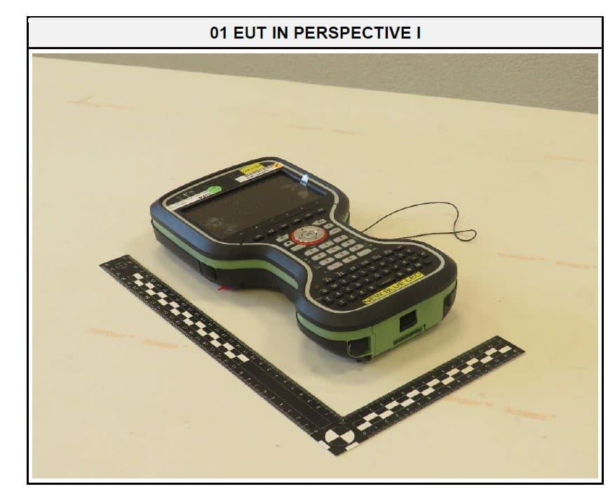
RFD-CSNGP
Jun 27, 2024CS20 Basic
Equipment Class
JAB - Part 15 Class B Digital DeviceRFD-ICG120
Jan 25, 2024iCG120 GNSS Receiver
Equipment Class
DSS - Part 15 Spread Spectrum Transmitter
RFD-GR50W
Jan 11, 2024GNSS Reference Server with Wlan
Equipment Class
DTS - Digital Transmission System
RFD-ICG160
Mar 26, 2023iCG160 GNSS Receiver
Equipment Class
DSS - Part 15 Spread Spectrum Transmitter