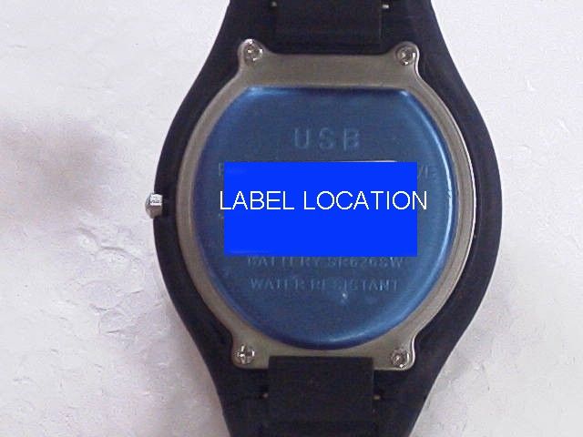
RFZUSBWATCHFLASH MEMORY WATCH
Xonix Holdings Limited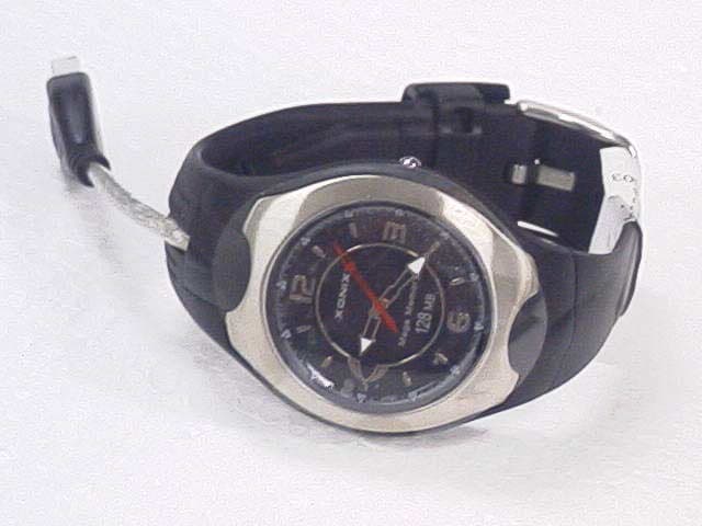
Click to zoom
Application Details
- Equipment Class
- JBP - Part 15 Class B Computing Device Peripheral
- Date of Grant
- Oct 07, 2003
- Application Purpose
- Original Equipment
- Date of Application
- Oct 07, 2003
- Equipment Note
- FLASH MEMORY WATCH
- Company
- Xonix Holdings Limited
- Country
- Hong Kong
Documents & Files
Document Text
Text extracted from the exhibit documents filed with the FCC. Open a document above to read the original.
Users Manual
U-Storage User’s Manual Version 1.0 Introduction Thank you for purchasing the U-Storage device. The manual explains how to use the U-Storage software bundled with the device. Safety Precautions Please follow the safety precautions carefully before you use the U-Storage device and the application software (the product). Make sure that you use the product correctly according to the procedures described in this guide. Warnings This mark indicates topics that could lead to serious injury of your body or damage of the product if ignored or handled incorrectly. _____________________________________________________________________ Warnings _____________________________________________________________________ ! Do not attempt to disassemble or alter any part of the product that is not described in this guide. ! Do not allow the product to come into contact with water or other liquids. In the event that water or other liquids enter the interior, immediately unplug the product from the computer. Continued use of the product may result in fire or electrical shock. Please consult your product distributor or the closest support center. ! Do not handle the product to do the plug and unplug operation if your hands are wet. Otherwise it will cause electrical shock. ! Do not place the product near a heat source or expose them to direct flame or heat. ! Never place the product close to equipment generating strong electromagnetic fields. Exposure to strong magnetic fields may cause malfunctions or corrupt data. ! protect the USB plug from salt water or any corrosive liquid to ensure the reliable connection. ! make sure the plug is dry before you connect U-Storage to computer in case the humidity results in short circuit which might damage your computer in succession. ! Hold the USB plug to disconnect U-Storage from computer. Never unplug by only holding the watch or wire to avoid the break of the wire. Also do no bend the wire severely during the plug and unplug operation to prolong the wire life. ! recommend frequent cleaning of accumulated residue inside the plug to prolong the product life. ! The manufacturer is not responsible for any radio or TV interference caused by unauthorized modifications to the equipment. Such modifications could void the User’s authority to operate the equipment. FCC Notice: This equipment has been tested and found to comply with the limits for a Class B digital device, pursuant to Part 15 of the FCC Rules. These limits are designed to provide reasonable protection against harmful interference in a residential installation. This equipment generates, uses and can radiate radio frequency energy and, if not installed and used in accordance with the instructions, may cause harmful interference to radio communications. However, there is no guarantee that interference will not occur in a particular installation. If this equipment does cause harmful interference to radio or television reception, which can be determined by turning the equipment off and on, the user is encouraged to try to correct the interference by one or more of the following measures: - Reorient or relocate the receiving antenna. - Increase the separation between the equipment and receiver. - Connect the equipment into an outlet on a circuit different from that to which the receiver is connected. - Consult the dealer or an experienced radio/TV technician for help. How to Set Time ! Pull out the crown when the second hand arrives at 12 o’clock position. ! Turn the crown in either direction to set hour and minute. ! Push the crown to the normal position to start How to change battery Please follow the procedures as below: 1 Unscrew the case back of the watch 2 Unscrew the CBA 3 Lift the CBA as showed in the picture 4 Remove the red insulator and replace the battery, screw back the CBA first and then the case back System Requirements There are minimum hardware and software requirements that must be satisfied to ensure the product to function properly. ! Computer Model IBM PC/AT Compatible, Power Macintosh, PowerBook, iMAC or iBook ! OS Windows 98 Second Edition, Windows Millennium Edition (Windows ME), Windows 2000, Windows XP, Linux 2.4 or higher, Mac OS 9.0 or higher ! Interface USB ! Free Hard Disk Space 3 MB and more # Windows 98 SE does not support default Mass Storage Driver. You have to install the driver bundled with the product. # The product can use the default driver in most of the OS. If you want to run the application software bundled with the product, install the vendor driver by the “U-StorageTools1.0.exe” utility. Then, the application software will work properly. # The application software only can run with Microsoft Windows OS. # However, the U-Storage basic functions can be supported in all OS listed above. Guide to Components USB Interface: The interface connects to the USB port of the computer. LED Display: This LED Display will show the status of the device. Once the device is in operation, the LED will flash quickly. Basic Functions 1. Plug and Play When you plug the device into the USB port of your computer, you will see a “Removable Disk” icon in the file manager window. In Macintosh, once you plug the U-Storage into the USB port. You can see the disk icon in the “Desktop”. In Linux OS, you can mount the device by the following instruction. Execute cd /etc/sysconfig/ ( cat /etc/sysconfig/hwconf | more ) Check the device information in hwconf write down the mount point. Make a directory in /mnt (ex: mkdir /mnt/usbHD ) Then, execute mount /dev/sda1 /mnt/usbHD (if mount point was .dev/sda) 2. Read and Write You can retrieve or store files in the device as a hard disk. The read/write operation of the device is the same as that of a hard disk. 3. Unplug You can remove the device after you finish the action with the device. However, in Windows ME and Windows 2000, please follow the safe removal procedure. You can find a safe removal icon in your computer’s notification area. Double click the “…
Text truncated - open the document above for the full version.
Block Diagram
Block Diagram
Test Report
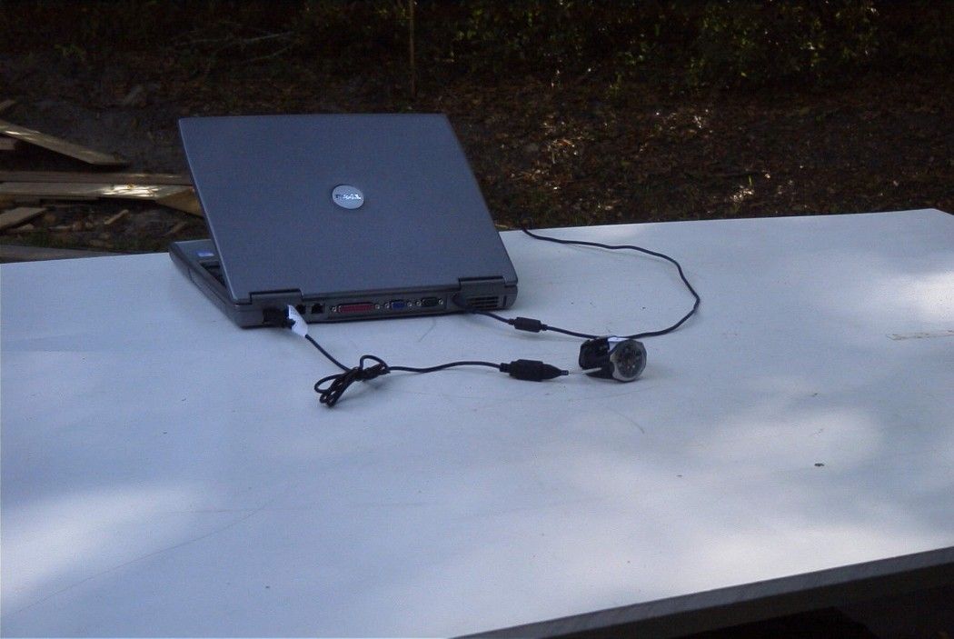
APPLICANT: XONIX HOLDINGS LIMITED FCC ID: RFZUSBWATCH REPORT #: X\XONIX_RFZ\1221HT3\1221HT3TestReport.doc TABLE OF CONTENTS LIST TABLE OF CONTENTS LIST APPLICANT: XONIX HOLDINGS LIMITED FCC ID: RFZUSBWATCH TEST REPORT CONTAINING: PAGE 1......TEST EQUIPMENT LIST PAGE 2......TEST PROCEDURES PAGE 3......RADIATION INTERFERENCE TEST DATA EXHIBITS CONTAINING: EXHIBIT 1............BLOCK DIAGRAM EXHIBIT 2............SCHEMATIC EXHIBIT 3............INSTRUCTION MANUAL EXHIBIT 4............SAMPLE OF FCC ID LABEL EXHIBIT 5............LOCATION OF FCC ID LABEL EXHIBIT 6............EXTERNAL PHOTOGRAPHS EXHIBIT 7............INTERNAL PHOTOGRAPHS EXHIBIT 8............TEST SET UP PHOTO – RADIATED EMISSIONS APPLICANT: XONIX HOLDINGS LIMITED FCC ID: RFZUSBWATCH REPORT #: X\XONIX_RFZ\1221HT3\1221HT3TestReport.doc Page 1 of 3 Equipment List Device Manufacturer Model Serial Number Cal/Char Date Due Date 3/10-Meter OATS TEI N/A N/A Listed 3/26/01 3/26/04 3-Meter OATS TEI N/A N/A Listed 1/13/03 1/13/06 Biconnical Antenna Eaton 94455-1 1057 CAL 3/18/03 3/18/05 Biconnical Antenna Eaton 94455-1 1096 CAL 10/1/01 10/1/03 Biconnical Antenna Electro-Metrics BIA-25 1171 CAL 4/26/01 4/26/03 Blue Tower Quasi-Peak Adapter HP 85650A 2811A01279 CAL 4/15/03 4/15/05 Blue Tower RF Preselector HP 85685A 2926A00983 CAL 4/15/03 4/15/05 Blue Tower Spectrum Analyzer HP 8568B 2928A04729 2848A18049 CAL 4/15/03 4/15/05 LISN Electro-Metrics ANS-25/2 2604 CAL 10/9/01 10/9/03 LISN Electro-Metrics EM-7820 2682 CAL 3/12/03 3/12/05 Log-Periodic Antenna Eaton 96005 1243 CAL 5/8/03 5/8/05 Log-Periodic Antenna Electro-Metrics EM-6950 632 CHAR 10/15/01 10/15/03 Log-Periodic Antenna Electro-Metrics LPA-25 1122 CAL 10/2/01 10/2/03 Log-Periodic Antenna Electro-Metrics LPA-30 409 CAL 3/4/03 3/4/05 Silver Tower Preamplifier HP 8449B 3008A01075 CHAR 1/28/02 1/28/04 Silver Tower Quasi-Peak Adapter HP 85650A 3303A01844 CAL 10/14/02 10/14/04 Silver Tower RF Preselector HP 85685A 2620A00294 CAL 10/14/02 10/14/04 Silver Tower Spectrum Analyzer HP 8566B Opt 462 3552A22064 3638A08608 CAL 10/14/02 10/14/04 Tan Tower Preamplifier HP 8449B-H02 3008A00372 CHAR 3/4/01 3/4/03 Tan Tower Quasi-Peak Adapter HP 85650A 3303A01690 CAL 8/31/01 8/31/03 Tan Tower RF Preselector HP 85685A 3221A01400 CAL 8/31/01 8/31/03 Tan Tower Spectrum Analyzer HP 8566B Opt 462 3138A07786 3144A20661 CAL 8/31/01 8/31/03 APPLICANT: XONIX HOLDINGS LIMITED FCC ID: RFZUSBWATCH REPORT #: X\XONIX_RFZ\1221HT3\1221HT3TestReport.doc Page 2 of 3 TEST PROCEDURE GENERAL: This report shall NOT be reproduced except in full without the written approval of TIMCO ENGINEERING, INC. Shielded interface cables were used in all cases except for cables connecting to the telephone line and the power cords. A test program was run which filled the screen with H's and also with the modem dialing out. Peripherals were turned on and operating. RADIATION INTERFERENCE: The test procedure used was ANSI STANDARD C63.4-1992 using a HEWLETT PACKARD spectrum analyzer with a preselector. The bandwidth of the spectrum analyzer was 100 kHz with an appropriate sweep speed. The analyzer was calibrated in dB above a microvolt at the output of the antenna. The resolution bandwidth was 100KHz and the video bandwidth was 300KHz. The ambient temperature of the UUT was 77ºF with a humidity of 62%. FORMULA OF CONVERSION FACTORS: The Field Strength at 3m was established by adding the meter reading of the spectrum analyzer (which is set to read in units of dBuV) to the antenna correction factor supplied by the antenna manufacturer. The antenna correction factors are stated in terms of dB. The gain of the Preselector was accounted for in the Spectrum Analyzer Meter Reading. Example: Freq (MHz) METER READING + ACF = FS 33 20 dBuV + 10.36 dB = 30.36 dBuV/m @ 3m ANSI STANDARD C63.4-1992 10.1.7 MEASUREMENT PROCEDURES: The UUT was placed on a table 80 cm high and with dimensions of 1m by 1.5m. The UUT was placed in a manner that was representative of the way the EUT would be used. If the EUT had any peripherals, they were attached and placed in a similar manner. The table used for radiated measurements is capable of continuous rotation. When an emission was found, the table was rotated to produce the maximum signal strength. At this point, the antenna was raised and lowered from 1m to 4m. The antenna was placed in both the horizontal and vertical planes. In addition, in the event of the test being for a computer set up, the modem and printer positions were swapped and cables were manipulated as much as possible. The monitor was not moved, as that would not represent a typical situation configuration. APPLICANT: XONIX HOLDINGS LIMITED FCC ID: RFZUSBWATCH REPORT #: X\XONIX_RFZ\1221HT3\1221HT3TestReport.doc Page 3 of 3 APPLICANT: XONIX HOLDINGS LIMITED FCC ID: RFZUSBWATCH NAME OF TEST: RADIATED SPURIOUS EMISSIONS RULES PART NO.: 15.109(a) - Class B Computing Device REQUIREMENTS: 30-88 MHz 40.0 dBuV/m measured at 3 meters 88-216 MHz 43.5 dbuV/m 216-960 MHz 46.0 dbuV/m ABOVE 960 MHz 54.0 dbuV/m TEST CONFIGURATION: DELL LAPTOP LATITUDE D600 FCC ID: QDS_BRCM1005_D MODEL: PPO5L TEST DATA: Emission Frequency MHz Meter Reading dBuV ANT. POLARITY Coax Loss dB Correction Factor dB Field Strength dBuV/m Margin dB 47.99 18.4 H 0.78 12.24 31.42 8.58 47.99 21.9 V 0.78 12.24 34.92 5.08 143.97 17.5 H 1.38 15.86 34.74 8.76 143.97 19.2 V 1.38 15.86 36.44 7.06 191.96 9.8 H 1.74 14.75 26.29 17.21 191.96 11.1 V 1.74 14.75 27.59 15.91 287.93 6.0 H 2.15 14.48 22.63 23.37 287.93 8.9 V 2.15 14.48 25.53 20.47 384.91 9.4 H 2.71 15.70 27.81 18.19 431.90 4.8 H 2.90 16.90 24.60 21.40 431.90 5.6 V 2.90 16.90 25.40 20.60 TEST PROCEDURE: ANSI STANDARD C63.4-1992. The spectrum was scanned from 30 to 1000 MHz. The unit was measured at Timco Engineering Inc. 849 N.W. State Road 45, Newberry, FL 32669. TEST RESULTS: The unit DOES appear to meet the FCC requirements. PERFORMED BY: NAM NGUYEN DATE: 9/10/03
Contact Information
Applicant
Maggie Leung(Assistant Sales Manager)
Test Firm
Timco Engineering, Inc.S Sanders
Technical Specifications
| # | Rule Parts | Frequency Range | Power Output |
|---|---|---|---|
| 1 | 15B | - | - |
Other Applications from Xonix Holdings Limited
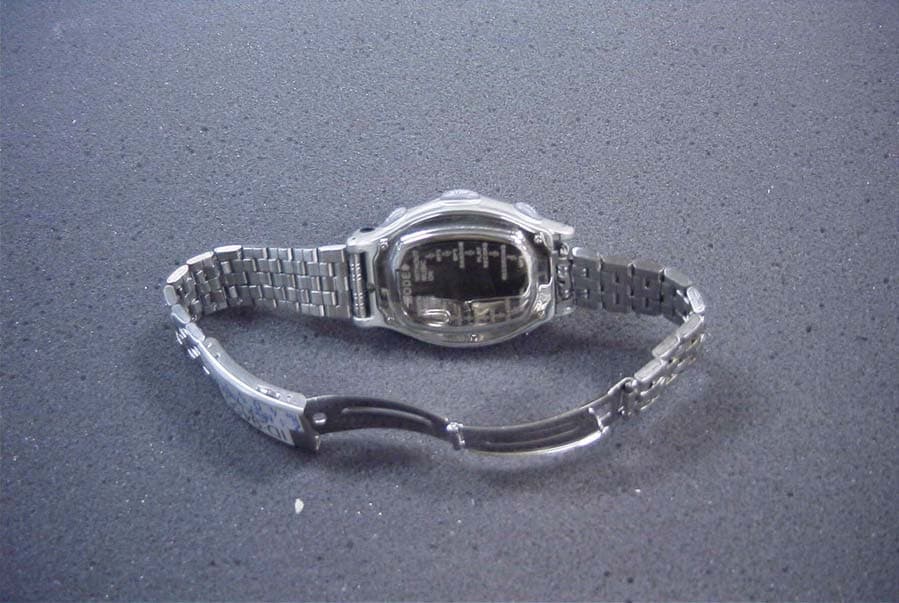
RFZMTUSB
Jan 11, 2005MP3 & DIGITAL RECORDER WATCH
Equipment Class
JBP - Part 15 Class B Computing Device Peripheral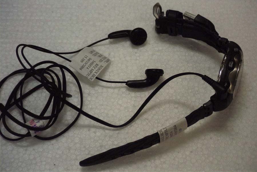
RFZMP3USB
May 17, 2004MP3 AND DIGITAL RECORDER WATCH
Equipment Class
JBP - Part 15 Class B Computing Device Peripheral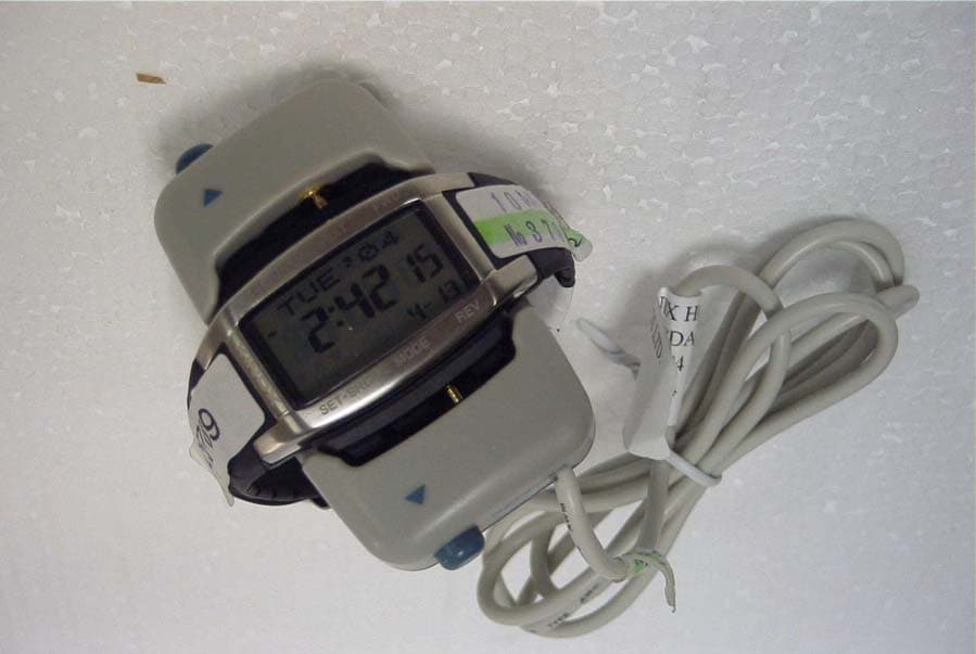
RFZPDATWUSB
May 10, 2004DATA BANK WATCH
Equipment Class
JBP - Part 15 Class B Computing Device Peripheral