RG375320TXIn/Out Thermometer w/ Radio-Controlled Clock
Primex Asia Limited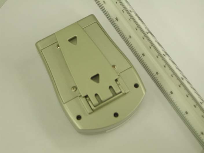
Click to zoom
Application Details
- Equipment Class
- DSC - Part 15 Security/Remote Control Transmitter
- Date of Grant
- Nov 18, 2003
- Application Purpose
- Original Equipment
- Date of Application
- Nov 18, 2003
- Equipment Note
- In/Out Thermometer w/ Radio-Controlled Clock
- Frequency Range
- 433.92000000 - 433.92000000
- Company
- Primex Asia Limited
- Country
- Hong Kong
Documents & Files
Document Text
Text extracted from the exhibit documents filed with the FCC. Open a document above to read the original.
Users Manual
Page 1 Congratulation on your purchase of an Atomix Radio Controlled clock. Radio Controlled technology allows for the most accurate time keeping available as well as automatic changes for Daylight Saving Time (DST). Atomix... the first name in Radio Controlled timekeeping. Clock Specifications • Receives 60KHz WWVB signal transmitted by NIST in Fort Collins, Colorado • Automatic time and date adjustment once the Radio Controlled (RC) signal is received. • Hour, minute, second and calendar display with day-of-the-week display from January 1, 2000 to December 31, 2099 • Temperature measurement range : Indoor main unit: 32F - 122F (0C - 50C) Wireless remote unit: 14F - 122F (-10C - 50C) • A maximum of 3 remote sensors can be used with this unit. Additional sensors are available separately. • Transmission range: up to 100ft. in an open area • Temperature resolution: 0.1 degree • Main unit can be mounted on a wall or used on a desk or table by unfolding the attached legs. INSTRUCTION MANUAL ATTENTION For the first installation, insert the batteries in the main unit and then the remote sensor. Battery installation Atomix clock Insert 3 “AA” alkaline batteries into the main unit. (Batteries not included) Remote sensor Insert 2 “AAA” alkaline batteries into the remote unit. (Batteries not included) Four screws need to be removed to access the battery compartment. Getting Started Wireless Thermometer Setup • Insert batteries in the main unit first and then insert batteries in the remote sensor. • On the remote sensor, press “Tx” or “Reset” button to send a signal to the main unit. • On the remote sensor, press the C/F button located under the cover and to select between Celsius and Fahrenheit temperature readings. (This function is available of remote sensor with display unit) • The unit is possible handle up to 3 individual remote sensors. One remote sensor included. The first remote sensor will Page 2 log in as channel 1. • To add an additional remote sensor, please make sure batteries are in the main unit first, than insert batteries in the additional sensor and press “Tx” or “Reset” button. The main unit automatically searches for an open channel to register the signal. • The remote sensor has a range of up to 100 feet in an open area and without barriers. Walls, fences and buildings will decrease the transmitter’s effective range. Replacing Batteries • When replacing batteries for the remote sensor, the channel in the main unit must be cleared. This can be done by selecting the respective channel (channel 1 if there is only 1 sensor) and pressing the “Channel” button for 3 seconds. • When replacing batteries for the main unit, please remove batteries from all remote sensors and re-install the batteries sequentially in the sensors according to the desired channel. Then please follow the above “Wireless Thermometer Setup” procedure. Atomix clock: First reception after inserting batteries • After inserting batteries in the Atomic clock, it will show “12:56 AM ” and start to search for the wireless thermometer data. • Until the clock reaches 1:00 AM , the Atomix clock will start search for the WWVB signal for 10 minutes. • In optimal conditions, the correct time will be displayed within 3 to 5 minutes. • The tower and wave icon will keep scrolling while the clock is searching for the RC signal. This is normal and indicates the radio control circuitry is working. • When the 4 “Wave” icons stop scrolling and remain showing it indicates successful reception of the RC time single. Auto mode setting • After installation of batteries or after being reset, the clock will follow the “First reception after inserting batteries” procedure. • If the clock fails to receive the signal in the first reception, it will repeat a reception every hour until 2:00 AM and go to “Automatic time update” mode. If the unit still cannot receive the RC signal after “Automatic time update” mode, it will search again at 2:00 AM the next day. • Once RC signal successfully received, the unit will automatic update a time by “Automatic time update” mode. Page 3 Automatic time update • The clock will automatically update its time at 2:00 AM . • If automatic time update fails, the clock will repeat the procedure 3 times in the next 3 hours. If the unit still cannot receive a RC signal, it will search again at 2:00 AM the following day. PLEASE NOTE: This clock is pre-set to show the Pacific Standard Time (PST) with Daylight Saving Time (DST) as a factory setting. Please adjust the switches on the back of the clock for your local time zone. IMPORTANT 1: When your Atomix clock is searching for or receiving the RC signal, it will ignore any signal or data from remote sensor(s). IMPORTANT 2: It is recommended to put your Atomix Clock near a window facing toward Fort Collins, Colorado. Televisions, computers, microwaves or other sources of electrical power may interfere with the clock ability to receive the RC signal. Please move the clock to another location if difficulty in signal reception is encountered. Atomix Clock manual setting Setting the Time Zone and Daylight Saving Time (DST) • Press “TIME ZONE” button to display the time in the proper time zone. Time Zone code: • PST = Pacific Standard Time • MST = Mountain Standard Time • CST = Central Standard Time • EST = Eastern Standard Time Slide “DST” switch to ON position except if the clock is used in an area without Daylight Saving Time (i.e. part of Arizona and Indiana) **Special attention to usage in Arizona and Indiana** Part of Arizona and Indiana do not use Daylight Saving Time (DST). Please slide the “DST” switch to the OFF position if the clock is used in an area without Daylight Saving Time. Page 4 To set the Time and Calendar • Please follow procedure listed below to adjust the Hour, Minute, Month, Date and Year sequentially. • Press “TIME/CALENDAR SET” button once and go to Hour set mode, press UP or DOWN button to set your desired Hour display. • Press “TIME/CALENDAR S…
Text truncated - open the document above for the full version.
External Photos
Test Setup FCCID : RG375320TX External Photo - front External Photo - rear
Internal Photos
Test Setup FCC ID : RG375320TX Internal Photo - 1 Internal Photo - 2 Test Setup FCC ID : RG375320TX Internal Photo - 3 Internal Photo - 4 Test Setup FCC ID : RG375320TX Internal Photo - 5
Test Report
• The test results reported in this test report shall refer only to the sample actually tested and shall not refer or be deemed to refer to bulk from which such a sample may be said to have been obtained. • This report shall not be reproduced except in full without prior authorization from Intertek Testing Services Hong Kong Limited. • For Terms And Conditions of the services, it can be provided upon request. • The evaluation data of the report will be kept for 3 years from the date of issuance. Intertek Testing Services Hong Kong Ltd. 2/F., Garment Centre, 576 Castle Peak Road, Kowloon, Hong Kong. Tel: (852) 2173 8888 Fax: (852) 2371 0521 Website: www.hk.intertek-etlsemko.com Primex Asia Limited Application For Certification (FCC ID: RG375320TX) Transmitter 0314464 DL/ Sandy October 27, 2003 INTERTEK TESTING SERVICES FCC ID: RG375320TX i LIST OF EXHIBITS INTRODUCTION EXHIBIT 1: General Description EXHIBIT 2: System Test Configuration EXHIBIT 3: Emission Results EXHIBIT 4: Equipment Photographs EXHIBIT 5: Product Labelling EXHIBIT 6: Technical Specifications EXHIBIT 7: Instruction Manual EXHIBIT 8: Miscellaneous Information INTERTEK TESTING SERVICES FCC ID: RG375320TX ii MEASUREMENT/TECHNICAL REPORT Primex Asia Limited - MODEL: ATOMIX 75320 NEW LONDON 75320 ACURITE 75320 Chaney Instrument 75320 Stoney Creek 75320 FCC ID: RG375320TX October 27, 2003 This report concerns (check one:) Original Grant X Class II Change Equipment Type: Low Power Transmitter (example: computer, printer, modem, etc.) Deferred grant requested per 47 CFR 0.457(d)(1)(ii)? Yes No X If yes, defer until: date Company Name agrees to notify the Commission by: date of the intended date of announcement of the product so that the grant can be issued on that date. Transition Rules Request per 15.37? Yes No X If no, assumed Part 15, Subpart C for intentional radiator - the new 47 CFR [08-20-02 Edition] provision. Report prepared by: Derek Leung Intertek Testing Services 2/F., Garment Center, 576, Castle Peak Road, HONG KONG. Phone: 852-2173-8504 Fax: 852-2371-0521 INTERTEK TESTING SERVICES FCC ID: RG375320TX iii Table of Contents 1.0 General Description............................................................................................ 2 1.1 Product Description ............................................................................................ 2 1.2 Related Submittal(s) Grants ............................................................................... 2 1.3 Test Methodology............................................................................................... 3 1.4 Test Facility........................................................................................................ 3 2.0 System Test Configuration ................................................................................. 5 2.1 Justification ........................................................................................................ 5 2.2 EUT Exercising Software.................................................................................... 5 2.3 Special Accessories ........................................................................................... 5 2.4 Equipment Modification ...................................................................................... 6 2.5 Measurement Uncertainty .................................................................................. 6 2.6 Support Equipment List and Description ............................................................. 6 3.0 Emission Results ................................................................................................ 8 3.1 Field Strength Calculation................................................................................... 9 3.2 Radiated Emission Configuration Photograph................................................... 11 3.3 Radiated Emission Data ................................................................................... 12 4.0 Equipment Photographs ................................................................................... 15 5.0 Product Labelling.............................................................................................. 17 6.0 Technical Specifications................................................................................... 19 7.0 Instruction Manual ............................................................................................ 21 8.0 Miscellaneous Information ............................................................................... 23 8.1 Measured Bandwidth........................................................................................ 24 8.2 Discussion of Pulse Desensitization.................................................................. 25 8.3 Calculation of Average Factor........................................................................... 26 8.4 Emissions Test Procedures .............................................................................. 27 INTERTEK TESTING SERVICES FCC ID: RG375320TX iv List of attached file Exhibit type File Description filename Test Report Test Report report.pdf Operation Description Technical Description descri.pdf Test Setup Photo Radiated Emission radiated photos.doc Test Report Bandwidth Plot bw.pdf External Photo External Photo external photos.doc Internal Photo Internal Photo internal photos.doc Block Diagram Block Diagram block.pdf Schematics Circuit Diagram circuit.pdf ID Label/Location Label Artwork and Location label.pdf User Manual User Manual manual.pdf Test Report Timing Diagram timing.pdf INTERTEK TESTING SERVICES FCC ID: RG375320TX 1 EXHIBIT 1 GENERAL DESCRIPTION INTERTEK TESTING SERVICES FCC ID: RG375320TX 2 1.0 General Description 1.1 Product Description The Equipment Under Test (EUT) is a Transmitter operating at 433MHz. The EUT is powered by 3.0V d.c. (2 x “AAA” size batteries). During normal uses, first insert batteries in the transmitter and press “Tx” or “Reset” button. The…
Text truncated - open the document above for the full version.
Test Setup Photos
Test Setup FCC ID : RG375320TX Radiated - front Radiated - rear
Contact Information
Applicant
Wai-Wah LEUNG(Senior Mechanical Engineer)
Technical Contact
Intertek Testing Services Hong Kong Ltd.Derek Leung
[email protected]852-2173-8504
2/F., Garment Centre, · Kowloon, · Hong Kong
Non-Technical Contact
Intertek Testing Services Hong KongDerek Leung
[email protected]852-2173-8504
Test Firm
Intertek Testing Services Hong KongBilly Chow
Technical Specifications
| # | Rule Parts | Frequency Range | Power Output |
|---|---|---|---|
| 1 | 15.231(e) | 433.92 MHz - 433.92 MHz | - |
Other Applications from Primex Asia Limited
RG3WGPS900M02
Feb 16, 2006GPS Wireless Clock System Slave
Equipment Class
DSS - Part 15 Spread Spectrum Transmitter
RG3WGPS900M01
Feb 15, 2006GPS Wireless Clock Systems Host
Equipment Class
DSS - Part 15 Spread Spectrum Transmitter