RG3WGPS900M01GPS Wireless Clock Systems Host
Primex Asia Limited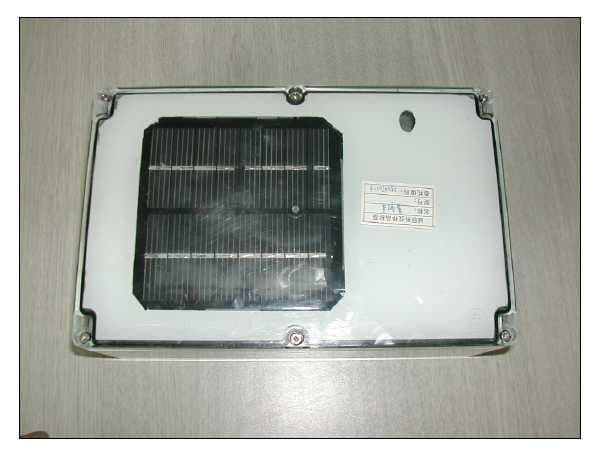
Click to zoom
Application Details
- Equipment Class
- DSS - Part 15 Spread Spectrum Transmitter
- Date of Grant
- Feb 15, 2006
- Application Purpose
- Original Equipment
- Date of Application
- Feb 15, 2006
- Equipment Note
- GPS Wireless Clock Systems Host
- Frequency Range
- 902.10000000 - 925.62000000
- Company
- Primex Asia Limited
- Country
- Hong Kong
Documents & Files
Document Text
Text extracted from the exhibit documents filed with the FCC. Open a document above to read the original.
Users Manual
GPS Wireless Clock Systems 1 Copyright © 2005 Primex Asia Limited - All rights reserved Primex Asia Limited Shenzhen Representative Office, NOV 10, 2005 Room AB, 29/F Haiying Building South Caitian Road Futian District, Shenzhen China 518003 0086-755-82913318 82913378 82915778 ext 807 www.primexwireless.com Product Guide Specification GPS Wireless Clock Systems Host Manual Version 1.03 Specifier Note: This section covers the Primex Wireless GPS Synchronized Clock System. Consult Primex Wireless for assistance in editing this section for the specific application. GPS Wireless Clock Systems 2 Copyright © 2005 Primex Asia Limited - All rights reserved Foreword 1. The user is cautioned that changes or modifications not expressly approved by Chaney Instruments Co. could void the user's authority to operate the equipment. 15.105: For a Class B digital device or peripheral, the instructions furnished the user shall include the following or similar statement, placed in a prominent location in the text of the manual: Note: This equipment has been tested and found to comply with the limits for a Class B digital device, pursuant to part 15 of the FCC Rules. These limits are designed to provide reasonable protection against harmful interference in a residential installation. This equipment generates, uses and can radiate radio frequency energy and, if not installed and used in accordance with the instructions, may cause harmful interference to radio communications. However, there is no guarantee that interference will not occur in a particular installation. If this equipment does cause harmful interference to radio or television reception, which can be determined by turning the equipment off and on, the user is encouraged to try to correct the interference by one or more of the following measures: —Reorient or relocate the receiving antenna. —Increase the separation between the equipment and receiver. —Connect the equipment into an outlet on a circuit different from that to which the receiver is connected. —Consult the dealer or an experienced radio/TV technician for help. 15.19 (labeling not on EUT due to size must be in manual: This device complies with part 15 of the FCC Rules. Operation is subject to the following two conditions: (1) This device may not cause harmful interference, and (2) this device must accept any interference received, including interference that may cause undesired operation. 2. The antenna used for this transmitter must be installed to provide a separation distance of at least 20 cm from all persons and must not be co-located or operating in conjunction with any other antenna or transmitter. Chapter I: Introduction The “GPS Wireless Clock Systems” is a revolutionary, synchronized timekeeping system- it is so easy to use. The GPS Receiver captures a time signal from the U.S. government's global positioning system (GPS) satellites, the time signal passing by the 902-928MHz Hoping Channels transceiver are sent to indoor Unit, then The 72MHz Transmitteranother systems then broadcasts the time to every Primex Wireless clock in your facility. So all of the clocks are synchronized to the exact second . Chapter II: Features 1. 900MHz FHSS transceiver with GPS receiver Power Supply Solar Battery TD13515X103/10-12-H(8V/1.55W) Ni-MH Battery 1.2V X4 GPS Wireless Clock Systems 3 Copyright © 2005 Primex Asia Limited - All rights reserved Operation Time 10 minutes every hour Transmitter distance 300 feet (OPEN SPACE) Operation Temperature -40 to +60 centigrade MCU PIC16F630 Transceiver CC1000 (900MHz IS Band, FHSS 50 Hopping Channels) GPS Receiver Baud rate 4800 (NEMA 0183) GPS Receiver Unit Himark Module (EN6808) Operation Time without solar 60 hours Full Charging Time 320 hours Chapter III: RF Module Specification Frequency 902MHz -928 MHz (ISM) CHANNEL FREQ. (MHz) CHANNEL FREQ. (MHz) CHANNEL FREQ. (MHz) 0 902.1 20 911.7 40 921.3 1 902.58 21 912.18 41 921.78 2 903.06 22 912.66 42 922.26 3 903.54 23 913.14 43 922.74 4 904.02 24 913.62 44 923.22 5 904.5 25 914.1 45 923.7 6 904.98 26 914.58 46 924.18 7 905.46 27 915.06 47 924.66 8 905.94 28 915.54 48 925.14 9 906.42 29 916.02 49 925.62 10 906.9 30 916.5 11 907.38 31 916.98 12 907.86 32 917.46 13 908.34 33 917.94 14 908.82 34 918.42 15 909.3 35 918.9 16 909.78 36 919.38 17 910.26 37 919.86 18 910.74 38 920.34 19 911.22 39 920.82 GPS Wireless Clock Systems 4 Copyright © 2005 Primex Asia Limited - All rights reserved Transmitter Power 5dBm Transmitter Time <400ms Receiver Sensitivity -105dBm Bandwidth of each channel Data Rate 2.4K Channel 50 A transmitter cycle : <400ms Antenna : Helix Antenna Connector: SMA-K Up to the standard for FCC 15.247 Chapter IV: Block Diagram GPS Receiver Charged Circuit 915MHz Transceive Power Management MCU PIC16F630 Power Management Backup Batteries Solar GPS 900 MHz FHSS HOST with GPS receive GPS Wireless Clock Systems 5 Copyright © 2005 Primex Asia Limited - All rights reserved Chapter V: Interface Solar panel NH rechargeable battery ATTENNA GPS Power On Switch GPS Wireless Clock Systems 6 Copyright © 2005 Primex Asia Limited - All rights reserved Tx Unit: a. If the transmitter does not receiver a valid GPS signal, the transmitter will be shut down within 10 minutes. If the receiver has received 3 packets with valid GPS signal, the transmitter also will be shut down. b. If the transmitter did not receive a valid GPS signal before it was shut down last times, After a hour it would be turn on. And the other hand, if it has received a valid GPS signal, it will turn on in next whole hour. GPS Wireless Clock Systems 7 Copyright © 2005 Primex Asia Limited - All rights reserved Chapter VI: Operation GPS Wireless Clock Systems 8 Copyright © 2005 Primex Asia Limited - All rights reserved Installation 1. The solar battery panel is suggested to install at the angle of 35, facing toward the west exactly. 2. The inner GPS module should be adjusted to the sea level by any possibility. Facing to the open air, while it’s inst…
Text truncated - open the document above for the full version.
Cover Letter(s)
ADT (Shanghai) Corporation 2F, Building C, No.1618, Yishan Rd., 201103, Shanghai, China Feb. 14, 2006 FCC ID: RG3WGPS900M01 The following lists are the answers for the comments on Feb. 11, 2006, please kindly have a review on it: 1) Information on the 731 cites a frequency range of 902.1 – 925.62 MHz and the test report shows 902.1 – 925.6 MHz (pages 5, 7, & 8) and test of 79 channels (902.1 – 925.58 MHz). The frequency list provided cites 902.0964 – 925.50504 MHz. What is correct? Please correct all affected exhibits as necessary. RE: The actual frequency range is correct that is 902.1 – 925.62 MHz. And should the client need to improve the documents that contain the information of frequency? The test report that shows the frequency range has all been changed with actual one. 2) This application should also include an appropriate RF exposure exhibit if the device is approved under 15.247. See attached example which would likely apply in this case. RE: Would you allow me to upload this tomorrow since it has not been come out yet. 3) Information in the test report (section 4.9), operational description, and users manual mention using an SMA-K joint connector. I am not familiar with “SMA-K” connector and can not seem to easily find information on the internet regarding what this is. However it appears to possibly be a standard type SMA connector. This would not be in compliance with 15.203. To meet the FCC requirements of 15.203, this would need to be reverse-polarity or reverse-sex connector. Please provide further information as necessary. Also, this may require updating affected exhibits to clarify as well. RE: It is dealt by mail already and please see the antenna photo. 4) Specific information on how the 15.247 TX meets several requirements has not been provided. Frequency Hopping Systems approved under 15.247 require detailed theory of operation to cover the following information below. For instance, a) is not simply answered with “random”. A sample pseudo-random list that would actually be generated needs to be provided or complete detail on how the list is generated. RE: The latest explanations have been sent by mail on 16:03, Feb. 14, 2006. Is there any other document needed to submit? 5) ~ 13) RE: Please see the test report. 14) & 15) RE: There are questions from our engineers which sent by mail on 16:31, Feb. 14, 2006.
Cover Letter(s)
Dear Tim, Thank you. I'll add these when next upload. As to the frequency, there are new explanations. Due to its technicality, I translate it and also ask the client to translate one version in order to reduce the confusions that may occur within a minimum level. My version: The hopping is pseudorandomly. ME T HO D : As soon as the system is powered on, a random figure is produced (less than 50). This figure moves left for one time within each transmission (eliminating the used channel). Compared with the eliminated channel, if the channel which moves left is more than 50 or minuses 1 by the used channel, after all 50 channels are used, the channels are reset. Thus the system runs this procedure periodically, and when the receiver receives synchro-data it also begins to hop synchronically. If the receiver does not receive synchro-data then it may wait in the random channel. The client's version: Hopping frequency is changed to pseudo randomly hopping frequency. It will produce random data (less than or equal to 50) when RF system is powered on. The channel will move left once when transmitting once (except used channel). If new channel data(after left move) is more than 50 or equal to used channel, then this data will be decreased 1 until new channel data is not equal to used channel. After using up 50 channels, the channel indicator will be cleared as 0 and continue to the above process. Receiver starts to synchronized hopping frequency when receiving synchro data. If it does not receive the data, it will be waiting in the random channel. Transmitter sends the channel information of next hopping frequency when transmitting. Receiver will send back ACK and move to next channel defined by transmitter. Dear Major & Jerry, Here I attach the Chinese version. Please do me a favor when the confusions come up due to something that not translated well. è°ƒé¢‘æ› ́改: 改ä ̧ºä¼ªéš 机跳频. æ-¹æ³•,ä ̧Šç”μ开始系统产生ä ̧€ä ̧ªçœŸéš 机数(å° äºŽç-‰äºŽ50),æ ̄ å ‘å°„ä ̧€æ¬¡å·¦ç§»ä ̧€ 次(å‰”é™¤å·²ç» ä½¿ç” ̈ä¿¡é “).æ ̄”è¾ƒå‰ƒé™¤ä¿¡é “,å¦‚æžœå·¦ç§»å¾—å‡ºçš„ä¿¡é “å¤§äºŽ50æ ˆ-è€...æ ̃ ̄ä»¥ä½¿ç” ̈çš„ä¿¡é “è¿™è¿™ä ̧ªæ•°å‡ 1,50ä ̧ªä¿¡é “éƒ½ä½¿ç” ̈å Ž,ä¿¡é “ä½¿ç” ̈æ ‡å¿— æ ̧...零.å ‘å°„ä ̧€æ¬¡å·¦ç§»ä ̧€æ¬¡(å‰”é™¤å·²ç» ä½¿ç” ̈ä¿¡é “).æ ̄”è¾ƒå‰ƒé™¤ä¿¡é “,å¦‚æžœå·¦ç§ »å¾—å‡ºçš„ä¿¡é “å¤§äºŽ50æˆ-è€...æ ̃ ̄ä»¥ä½¿ç” ̈çš„ä¿¡é “è¿™è¿™ä ̧ªæ•°å‡ 1.如æ-¤å¾ªçŽ ̄,接 æ”¶æœºåœ ̈æ”¶åˆ°å Œæ-¥æ•°æ ®å Žå¼€å§‹å Œæ-¥è·³é¢‘.å¦‚æžœæ²¡æœ‰æ”¶åˆ°å Œæ-¥åˆ™åœ ̈éš æœºä¿¡é “ç-‰å¾.... Thank you very much ※※※※※※※※※※※※※※※※※※※※ ADT (Shanghai) Corporation 2F, C Building, No.1618, Yi Shan Rd., Shanghai,China Lily Liu
Operational Description
RPSMA-KSMARPSMA-K RPSMA-KSMA
Operational Description
Dear Tim , The explanation s of the hopping is as following: It will produce a random data (less than or equal to 50) when the RF system is powered on. The channels will move left for one time within each transmission ( See note below)(eliminating the used channel). Compared with the eliminated channel, if the new channel data (after left move) is more than 50 or equal to the used channel, then this data will be decreased 1 (If it meets the used channel then it will continue to minus 1 until the new channel data is not equal to the used one). After using up 50 channels, the channel indicator will be reset and continue to the above process. Hopping frequency is changed to pseudo randomly hopping frequency. The method is as below: Note: Our understanding of the sentence that marked red is as below: The 8 bit binary register which contains the channel number will shift left by one bit and then produce one channel number as the next channel number. Hopping frequency is changed to pseudo randomly hopping frequency. The method is as below: Where: A: the previous channel number B: the next channel number Firstly, A+A=B Secondly, If B=<50, when B is not used, B is the next channel number; If B > 50, B = B-1 until B=<50 Example code(binary) channel number (HEX) channel note 110001 31 49 NA 100010 22 34 NA 000100 4 4 NA 001000 8 8 NA 010000 10 16 NA 100000 20 32 NA 000000 0 0 NA Best wishes ※※※※※※※※※※※※※※※※※※※※ ADT (Shanghai) Corporation 2F , C Building, No.1618, Yi Shan Rd., Shanghai,China Lily Liu 110000 30 48 000000 → 111111(0-1=111111) 111111channel number(HEX)=3F>31 so next code is 110000=30(HEX) 011111 1F 20 110000 → 100000(have used) 100000-000001=011111=1F(HEX) ......
Operational Description
GPS Wireless Clock Systems 1 Copyright © 2005 Primex Asia Limited - All rights reserved Primex Asia Limited Shenzhen Representative Office, NOV 10, 2005 Room AB, 29/F Haiying Building South Caitian Road Futian District, Shenzhen China 518003 0086-755-82913318 82913378 82915778 ext 807 www.primexwireless.com GPS Wireless Clock Systems Host Operational Description Version 1.03 Specifier Note: This section covers the Primex Wireless GPS Synchronized Clock System. Consult Primex Wireless for assistance in editing this section for the specific application. GPS Wireless Clock Systems 2 Copyright © 2005 Primex Asia Limited - All rights reserved Foreword 1. The user is cautioned that changes or modifications not expressly approved by Chaney Instruments Co. could void the user's authority to operate the equipment. 15.105: For a Class B digital device or peripheral, the instructions furnished the user shall include the following or similar statement, placed in a prominent location in the text of the manual: Note: This equipment has been tested and found to comply with the limits for a Class B digital device, pursuant to part 15 of the FCC Rules. These limits are designed to provide reasonable protection against harmful interference in a residential installation. This equipment generates, uses and can radiate radio frequency energy and, if not installed and used in accordance with the instructions, may cause harmful interference to radio communications. However, there is no guarantee that interference will not occur in a particular installation. If this equipment does cause harmful interference to radio or television reception, which can be determined by turning the equipment off and on, the user is encouraged to try to correct the interference by one or more of the following measures: —Reorient or relocate the receiving antenna. —Increase the separation between the equipment and receiver. —Connect the equipment into an outlet on a circuit different from that to which the receiver is connected. —Consult the dealer or an experienced radio/TV technician for help. 15.19 (labeling not on EUT due to size must be in manual: This device complies with part 15 of the FCC Rules. Operation is subject to the following two conditions: (1) This device may not cause harmful interference, and (2) this device must accept any interference received, including interference that may cause undesired operation. 2. The antenna used for this transmitter must be installed to provide a separation distance of at least 20 cm from all persons and must not be co-located or operating in conjunction with any other antenna or transmitter. Chapter I: Introduction The “GPS Wireless Clock Systems” is a revolutionary, synchronized timekeeping system- it is so easy to use. The GPS Receiver captures a time signal from the U.S. government's global positioning system (GPS) satellites, the time signal passing by the 902-928MHz Hoping Channels transceiver are sent to indoor Unit, then The 72MHz Transmitteranother systemthen broadcasts the time to every Primex Wireless clock in your facility. So all of the clocks are synchronized to the exact second . Chapter IV: Block Diagram GPS Wireless Clock Systems 3 Copyright © 2005 Primex Asia Limited - All rights reserved Chapter V: Interface GPS Receiver Charged Circuit 915MHz Transceive Power Management MCU PIC16F630 Power Management Backup Batteries Solar GPS 900 MHz FHSS HOST with GPS receive GPS Wireless Clock Systems 4 Copyright © 2005 Primex Asia Limited - All rights reserved Solar panel NH rechargeable battery ATTENNA GPS Tx Unit: Power On Switch GPS Wireless Clock Systems 5 Copyright © 2005 Primex Asia Limited - All rights reserved a. If the transmitter does not receiver a valid GPS signal, the transmitter will be shut down within 10 minutes. If the receiver has received 3 packets with valid GPS signal, the transmitter also will be shut down. b. If the transmitter did not receive a valid GPS signal before it was shut down last times, After a hour it would be turn on. And the other hand, if it has received a valid GPS signal, it will turn on in next whole hour. GPS Wireless Clock Systems 6 Copyright © 2005 Primex Asia Limited - All rights reserved Chapter VI: Operation Installation 1. The solar battery panel is suggested to install at the angle of 35, facing toward the west exactly. 2. The inner GPS module should be adjusted to the sea level by any possibility. Facing to the open air, while it’s installed near the wall. 3. The receptor should be fixed in the well-receipting place. 4. After the installment is finished, power on, and the equipment is under working.
RF Exposure Info
FCC ID: RG3WGPS900M01 No SAR Evaluation Required if power is below the following threshold: Tunable Range F(GHz) Low F(GHz) High Center of Tunable Band (GHz) 60/f SAR Limitation mW 902.1 925.62 913.14 65.71 Maximum measured transmitter power: Pout Conducted (mW) Maximum Antenna Gain dBi Pout EIRP (mW) 0.1122 0.12 0.4168 Threshold for no SAR evaluation is 65.71 mW Maximum TX Power is 0.1122 mW Conducted and 0.4168 mW EIRP Conclusion: No SAR evaluation required since maximum Transmitter Pout (both conducted and EIRP) is below FCC threshold
Test Report
FCC ID: RG3WGPS900M01 Report No.: 051106FIA01 1 Report Format Version 1.0.0 FCC TEST REPORT REPORT NO.: 051106FIA01 MODEL NO.: GPS050520 RECEIVED: Nov. 2, 2005 TESTED: Dec. 7, 2005 ~ Jan. 16, 2006 ISSUED: Jan. 17, 2006 APPLICANT: Hong Kong Primex Asia Limited Shenzhen Representative Office ADDRESS: AB 29/F HaiYing Building South Caitian Road Futian District Shenzhen China ISSUED BY: ADT (Shanghai) Corporation ADDRESS: 2F, Building C, No.1618, Yishan Rd., 201103, Shanghai, China This test report consists of 62 pages in total. It may be duplicated completely for legal use with the approval of the applicant. It should not be reproduced except in full, without the written approval of our laboratory. The client should not use it to claim product endorsement by A2LA, NVLAP or any government agencies. The test results in the report only apply to the tested sample. ADT (Shanghai) Corporation FCC ID: RG3WGPS900M01 Report No.: 051106FIA01 2 Report Format Version 1.0.0 TABLE OF CONTENTS 1 CERTIFICATION ............................................................................................................4 2 SUMMARY OF TEST RESULTS ...................................................................................5 2.1 MEASUREMENT UNCERTAINTY .................................................................................6 3 GENERAL INFORMATION ............................................................................................7 3.1 GENERAL DESCRIPTION OF EUT ..............................................................................7 3.2 DESCRIPTION OF TEST MODES ................................................................................8 3.2.1 CONFIGURATION OF SYSTEM UNDER TEST............................................................8 3.2.2 TEST MODE APPLICABILITY AND TESTED CHANNEL DETAIL ................................9 3.2.3 GENERAL DESCRIPTION OF APPLIED STANDARDS.............................................. 11 3.2.4 DESCRIPTION OF SUPPORT UNITS......................................................................... 11 4 TEST TYPES AND RESULTS......................................................................................12 4.1 CONDUCTED EMISSION MEASUREMENT...............................................................12 4.1.1 LIMITS OF CONDUCTED EMISSION MEASUREMENT ............................................12 4.1.2 TEST RESULTS...........................................................................................................12 4.2 RADIATED EMISSION MEASUREMENT....................................................................13 4.2.1 LIMITS OF RADIATED EMISSION MEASUREMENT .................................................13 4.2.2 TEST INSTRUMENTS .................................................................................................14 4.2.3 TEST PROCEDURES..................................................................................................15 4.2.4 DEVIATION FROM TEST STANDARD ........................................................................15 4.2.5 TEST SETUP ...............................................................................................................16 4.2.6 EUT OPERATING CONDITIONS ................................................................................16 4.2.7 TEST RESULTS...........................................................................................................17 4.3 UMBER OF HOPPING FREQUENCY USED ..............................................................35 4.3.1 LIMIT OF HOPPING FREQUENCY USED ..................................................................35 4.3.2 TEST INSTRUMENTS .................................................................................................35 4.3.3 TEST PROCEDURES..................................................................................................35 4.3.4 DEVIATION FROM TEST STANDARD ........................................................................35 4.3.5 TEST SETUP ...............................................................................................................35 4.3.6 TEST RESULTS...........................................................................................................36 4.4 DWELL TIME ON EACH CHANNEL............................................................................37 4.4.1 LIMIT OF DWELL TIME USED ....................................................................................37 4.4.2 TEST INSTRUMENTS .................................................................................................37 4.4.3 TEST PROCEDURES..................................................................................................37 4.4.4 DEVIATION FROM TEST STANDARD ........................................................................38 4.4.5 TEST SETUP ...............................................................................................................38 4.4.6 TEST RESULTS...........................................................................................................39 4.5 CHANNEL BANDWIDTH .............................................................................................43 4.5.1 LIMITS OF CHANNEL BANDWIDTH...........................................................................43 FCC ID: RG3WGPS900M01 Report No.: 051106FIA01 3 Report Format Version 1.0.0 4.5.2 TEST INSTRUMENTS .................................................................................................43 4.5.3 TEST PROCEDURE ....................................................................................................43 4.5.4 DEVIATION FROM TEST STANDARD ........................................................................44 4.5.5 TEST SETUP ...............................................................................................................44 4.5.6 EUT OPERATING CONDITION ........................................................................…
Text truncated - open the document above for the full version.
Contact Information
Applicant
Wai-Wah LEUNG(Senior Mechanical Engineer)
Technical Contact
ADT (Shanghai) CorporationWallace Pan
[email protected]86-21-6465-9091
2F, Building C, No. 1618, Yishan rd. · Shanghai · China
Test Firm
BUREAU VERITAS ADT (Shanghai) CorporationZhaoqian YU
Technical Specifications
| # | Rule Parts | Frequency Range | Power Output |
|---|---|---|---|
| 1 | 15C | 902.1 MHz - 925.62 MHz | 230.00 µW |
Other Applications from Primex Asia Limited
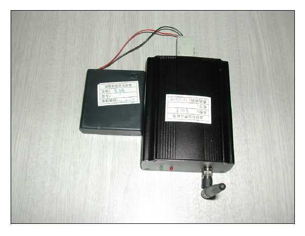
RG3WGPS900M02
Feb 16, 2006GPS Wireless Clock System Slave
Equipment Class
DSS - Part 15 Spread Spectrum Transmitter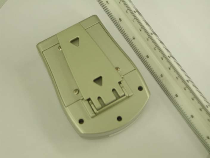
RG375320TX
Nov 18, 2003In/Out Thermometer w/ Radio-Controlled Clock
Equipment Class
DSC - Part 15 Security/Remote Control Transmitter