RG3WGPS900M02GPS Wireless Clock System Slave
Primex Asia Limited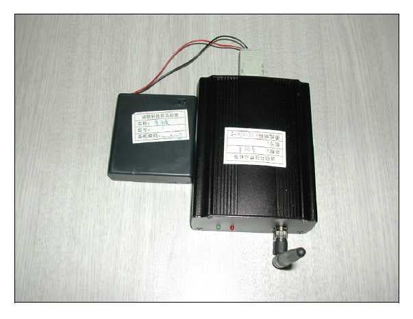
Click to zoom
Application Details
- Equipment Class
- DSS - Part 15 Spread Spectrum Transmitter
- Date of Grant
- Feb 16, 2006
- Application Purpose
- Original Equipment
- Date of Application
- Feb 15, 2006
- Equipment Note
- GPS Wireless Clock System Slave
- Frequency Range
- 902.10000000 - 925.62000000
- Company
- Primex Asia Limited
- Country
- Hong Kong
Documents & Files
Document Text
Text extracted from the exhibit documents filed with the FCC. Open a document above to read the original.
Users Manual
GPS Wireless Clock Systems 1 Copyright © 2005 Primex Asia Limited - All rights reserved Primex Asia Limited Shenzhen Representative Office, NOV 10, 2005 Room AB, 29/F Haiying Building South Caitian Road Futian District, Shenzhen China 518003 0086-755-82913318 82913378 82915778 ext 807 www.primexwireless.com Product Guide Specification GPS Wireless Clock Systems Slave Manual Version 1.03 Specifier Note: This section covers the Primex Wireless GPS Synchronized Clock System. Consult Primex Wireless for assistance in editing this section for the specific application. GPS Wireless Clock Systems 2 Copyright © 2005 Primex Asia Limited - All rights reserved Foreword 1. The user is cautioned that changes or modifications not expressly approved by Chaney Instruments Co. could void the user's authority to operate the equipment. 15.105: For a Class B digital device or peripheral, the instructions furnished the user shall include the following or similar statement, placed in a prominent location in the text of the manual: Note: This equipment has been tested and found to comply with the limits for a Class B digital device, pursuant to part 15 of the FCC Rules. These limits are designed to provide reasonable protection against harmful interference in a residential installation. This equipment generates, uses and can radiate radio frequency energy and, if not installed and used in accordance with the instructions, may cause harmful interference to radio communications. However, there is no guarantee that interference will not occur in a particular installation. If this equipment does cause harmful interference to radio or television reception, which can be determined by turning the equipment off and on, the user is encouraged to try to correct the interference by one or more of the following measures: —Reorient or relocate the receiving antenna. —Increase the separation between the equipment and receiver. —Connect the equipment into an outlet on a circuit different from that to which the receiver is connected. —Consult the dealer or an experienced radio/TV technician for help. 15.19 (labeling not on EUT due to size must be in manual: This device complies with part 15 of the FCC Rules. Operation is subject to the following two conditions: (1) This device may not cause harmful interference, and (2) this device must accept any interference received, including interference that may cause undesired operation. 2. The antenna used for this transmitter must be installed to provide a separation distance of at least 20 cm from all persons and must not be co-located or operating in conjunction with any other antenna or transmitter. Chapter I: Introduction The “GPS Wireless Clock Systems” is a revolutionary, synchronized timekeeping system- it is so easy to use. The GPS Receiver captures a time signal from the U.S. government's global positioning system (GPS) satellites, the time signal passing by the 902-928MHz Hoping Channels transceiver are sent to indoor Unit, then The 72MHz Transmitter another systems then broadcasts the time to every Primex Wireless clock in your facility. So all of the clocks are synchronized to the exact second . Chapter II: Features 1. 900MHz FHSS transceiver with 72MHz Sender Operation Temperature -40 to +60 centigrade MCU PIC16F630 GPS Wireless Clock Systems 3 Copyright © 2005 Primex Asia Limited - All rights reserved Receiver CC1000 (900MHz IS Band, FHSS 50 Hopping Channels) Baud rate 4800 (NEMA 0183) Chapter III: RF Module Specification Frequency 902MHz -928 MHz (ISM) CHANNEL FREQ. (MHz) CHANNEL FREQ. (MHz) CHANNEL FREQ. (MHz) 0 902.1 20 911.7 40 921.3 1 902.58 21 912.18 41 921.78 2 903.06 22 912.66 42 922.26 3 903.54 23 913.14 43 922.74 4 904.02 24 913.62 44 923.22 5 904.5 25 914.1 45 923.7 6 904.98 26 914.58 46 924.18 7 905.46 27 915.06 47 924.66 8 905.94 28 915.54 48 925.14 9 906.42 29 916.02 49 925.62 10 906.9 30 916.5 11 907.38 31 916.98 12 907.86 32 917.46 13 908.34 33 917.94 14 908.82 34 918.42 15 909.3 35 918.9 16 909.78 36 919.38 17 910.26 37 919.86 18 910.74 38 920.34 19 911.22 39 920.82 Transmitter Power 5dBm Transmitter Time <400ms Receiver Sensitivity -105dBm Bandwidth of each channel Data Rate 2.4K Channel 50 A transmitter cycle : <400ms GPS Wireless Clock Systems 4 Copyright © 2005 Primex Asia Limited - All rights reserved Antenna : Helix Antenna Connector: SMA-K Up to the standard for FCC 15.247 Chapter IV: Block Diagram *NOTE 72MHz transmitting system and WGPS system are individual. WGPS HOST forward GPS time signal to WGPS SLAVE at WGPS system. Then WGPS SLAVE send time signal to 72 MHz transmitting system via RX-232 interface. 72MHz transmitting system had gotten FCC certification. 915MHz Transceiver MCU PIC16F630 72MHz Sender MCU LCD Screen Power Management KEY Board AC Power 900MHz FHSS Slave with 72MHz Sender GPS Clock systems slave part 72M Sender systems GPS Wireless Clock Systems 5 Copyright © 2005 Primex Asia Limited - All rights reserved (FCC ID: PZ3-FM72). The communication mode and socket is RS-232 at this system. But it is not standard RS -232 interface, not directly connect with PC. Chapter V: Interface Rx Unit: a. LED direction- Green Flash It means Rx Unit has received data from GPS Wireless Clock Systems 6 Copyright © 2005 Primex Asia Limited - All rights reserved 900MHz transceiver Module and sent the data to 72 MHz sender (another systems) Red Waiting for the data from 900MHz transceiver Module b. When the receiver has received a valid packet, the green LED is flash for one time, and the green LED is off at other time. The red LED is flash when the receiver is transmitting data; others time the red LED is on. Chapter VI: Operation
Cover Letter(s)
American Telecommunications Certification Body Inc. 6731 Whittier Ave, McLean, VA 22101 February 11, 2006 RE: Hong Kong Primex Asia Limited Shenzhen Representative Office/Amoi Electronics Co., Ltd. FCC ID: RG3-WGPS900M02 After a review of the submitted information, I have a few comments on the above referenced Application. 1) Information on the 731 cites a frequency range of 902.1 – 925.62 MHz and the test report shows 902.1 – 925.6 MHz (pages 5, 7, & 8) and test of 79 channels (902.1 – 925.58 MHz). The frequency list provided cites 902.0964 – 925.50504 MHz. What is correct? Please correct all affected exhibits as necessary. 2) This application should also include an appropriate RF exposure exhibit if the device is approved under 15.247. See attached example which would likely apply in this case. 3) Information in the test report (section 4.9), operational description, and users manual mention using an SMA-K joint connector. I am not familiar with “SMA-K” connector and can not seem to easily find information on the internet regarding what this is. However it appears to possibly be a standard type SMA connector. This would not be in compliance with 15.203. To meet the FCC requirements of 15.203, this would need to be reverse-polarity or reverse-sex connector. Please provide further information as necessary. Also, this may require updating affected exhibits to clarify as well. 4) Specific information on how the 15.247 TX meets several requirements has not been provided. Frequency Hopping Systems approved under 15.247 require detailed theory of operation to cover the following information below. For instance, a) is not simply answered with “random”. A sample pseudo-random list that would actually be generated needs to be provided or complete detail on how the list is generated. a) pseudo random sample hopping list and how the pseudo random channels are selected. b) description of system receivers and how they have input bandwidths that match the hopping channel bandwidths of their corresponding transmitters and how they shift frequencies in synchronization with the transmitted signals c) Timing information of the system and how it meets equally on the average requirements. In addition, during absence of data, how does the system behave. It should always either continue to hop, or stop and start on the next frequency in the hop table. The device should not start back at the first channel in the hop list. d) How the device meets 15.247(g) and (h). e) If the system has different modes of operation that affect the above, the theory should cover each of these as well (i.e. different timing, data rates, etc). f) Comments further down mention the possibility of approving under 15.249. Please review remaining comments carefully. If 15.249 is used, the information given here is not necessary. 5) For Receiver emissions: When radiated Peak emissions exceed Average limits, FCC requires both peak and average data to be shown . Also, please note that many readings are shown as average only. In these cases we require peak. Also, please note that TX duty factor is not typical applicable to RX emissions. A duty factor based upon evaluation of any pulsing of the RX if applicable must be applied, not the TX. This may require evaluating each emission separately with peak and average detectors. Once finalized/corrected radiated emissions will need to be reviewed again in entirety due to the various concerns cited here and to follow. 6) Page 27 & 28: 1777 MHz is not 20 dB below fundamental measurements and also exceeds peak and average limits which therefore exceeds FCC requirements. Please review. z Page 2 February 13, 2006 7) Page 30 & 31: 1812 MHz is not 20 dB below fundamental measurements and also exceeds peak and average limits which therefore exceeds FCC requirements. Please review. 8) Page 33 & 34: 1846 MHz is not 20 dB below fundamental measurements and also exceeds peak and average limits which therefore exceeds FCC requirements. Please review. 9) Other TX emissions are still difficult to review. Please provide appropriate peak and average measurements for all readings so appropriate review can be performed. Using the duty factor shown, some measurements still appear over peak or average limit. Please provide all information for appropriate evaluation. 10) FYI....NOTE: Due to number of issues to review in test report, complete review of test report will be necessary upon correction. 11) Test data is showing 600 msec dwell/TX time per 20 seconds. This exceeds the maximum 400 msec limit. Please note that the 400 msec is a time of occupancy per channel (TX + RX), which would appear to be 600 msec. Please review. 12) Information in this application suggests an output power of 5 dBm. However results of power shown almost -13 dB below this. Was the device functioning properly? Was the setup properly corrected for cable loss during the measurement? Given the specifications of the module compared to the results, it appears that there is a concern with either the test method or test sample. Please review. However, if power is much lower than 0 dBm, it may also be possible to approve this device using 15.249. This will eliminate the need to provide all the theory shown above, but will require all emissions to meet 74 dBuV/m - Peak and 54 dBuV/m – AVG regardless of the frequency measured. Only 15.247 requires restricted bands to meet these limits, but other transmitters must meet these levels for ALL spurious emissions. Additionally 15.247 only requires a 20 dB down on the bandedge of 902-928 MHz, but 15.247 would be required to meet the general radiated measurements. This may be a problem at 902 MHz. 13) If approving to 15.247, Current bandedge emissions are shown with too large a span to ensure proper compliance at the bandedge. Please provide a bandedge plot with 902 and 928 MHz shown in the center of the screen with a 10 MHz span or less and the closest channel to the bandedge. Please use RBW = 100 kHz, VBW >…
Text truncated - open the document above for the full version.
Cover Letter(s)
American Telecommunications Certification Body Inc. 6731 Whittier Ave, McLean, VA 22101 February 16, 2006 RE: Hong Kong Primex Asia Limited Shenzhen Representative Office/Amoi Electronics Co., Ltd. FCC ID: RG3-WGPS900M02 After a review of the submitted information, I have a few comments on the above referenced Application. 1) I am not sure I follow the logic provided for the hop list. I could not recreate data in hop list. However if the sample lists provided are accurate, the list should be sufficient. If possible, it would be nice to actually show the logic from the first 2 or 3 channels cited – but as a minimum a confirmation of the list being correct is necessary. 2) RF exposure does not use maximum power given in test report. Please correct. 3) As long as some part of the system connects to AC, AC Powerline Conducted emissions are still applicable. Please note that 15.207(c) mentions connecting to AC indirectly. I.E. Since AC power feeds the 72 MHz sender unit via a 9VD adapter, AC emissions through the 72 MHz sender unit are still applicable. Please provide. 4) Powerline Conducted should be applicable to this device, therefore the PLC checkbox in section 3.2.2 should be checked. 5) ANSI C63.4 typically requires typical length cables to be attached to all ports or at least a nominal 1 meter length. Have prescans or evaluation of this device been done to determine how a normal cable length will affect the radiated results. The manual suggests a typical > 1 meter cable will be used. Currently testing appears to have been done without an appropriate cable attached. Please review. Timothy R. Johnson Examining Engineer mailto: [email protected] The items indicated above must be submitted before processing can continue on the above referenced application. Failure to provide the requested information may result in application termination. Correspondence should be considered part of the permanent submission and may be viewed from the Internet after a Grant of Equipment Authorization is issued. Please do not respond to this correspondence using the email reply button. In order for your response to be processed expeditiously, you must submit your documents through the AmericanTCB.com website. Also, please note that partial responses increase processing time and should not be submitted. Any questions about the content of this correspondence should be directed to the sender.
Cover Letter(s)
ADT (Shanghai) Corporation 2F, Building C, No.1618, Yishan Rd., 201103, Shanghai, China Feb. 14, 2006 FCC ID: RG3WGPS900M02 The following lists are the answers for the comments on Feb. 11, 2006, please kindly have a review on it: 1) Information on the 731 cites a frequency range of 902.1 – 925.62 MHz and the test report shows 902.1 – 925.6 MHz (pages 5, 7, & 8) and test of 79 channels (902.1 – 925.58 MHz). The frequency list provided cites 902.0964 – 925.50504 MHz. What is correct? Please correct all affected exhibits as necessary. RE: The actual frequency range is correct that is 902.1 – 925.62 MHz. And should the client need to improve the documents that contain the information of frequency? The test report that shows the frequency range has all been changed with actual one. 2) This application should also include an appropriate RF exposure exhibit if the device is approved under 15.247. See attached example which would likely apply in this case. RE: Would you allow me to upload this tomorrow since it has not been come out yet. 3) Information in the test report (section 4.9), operational description, and users manual mention using an SMA-K joint connector. I am not familiar with “SMA-K” connector and can not seem to easily find information on the internet regarding what this is. However it appears to possibly be a standard type SMA connector. This would not be in compliance with 15.203. To meet the FCC requirements of 15.203, this would need to be reverse-polarity or reverse-sex connector. Please provide further information as necessary. Also, this may require updating affected exhibits to clarify as well. RE: It is dealt by mail already and please see the antenna photo. 4) Specific information on how the 15.247 TX meets several requirements has not been provided. Frequency Hopping Systems approved under 15.247 require detailed theory of operation to cover the following information below. For instance, a) is not simply answered with “random”. A sample pseudo-random list that would actually be generated needs to be provided or complete detail on how the list is generated. RE: The latest explanations have been sent by mail on 16:03, Feb. 14, 2006. Is there any other document needed to submit? 5) ~ 11) & 14) ~ 15) RE: Please see the test report. 12) & 13) RE: There are questions from our engineers which sent by mail on 16:31, Feb. 14, 2006.
Cover Letter(s)
Dear Tim, Thank you. I'll add these when next upload. As to the frequency, there are new explanations. Due to its technicality, I translate it and also ask the client to translate one version in order to reduce the confusions that may occur within a minimum level. My version: The hopping is pseudorandomly. ME T HO D : As soon as the system is powered on, a random figure is produced (less than 50). This figure moves left for one time within each transmission (eliminating the used channel). Compared with the eliminated channel, if the channel which moves left is more than 50 or minuses 1 by the used channel, after all 50 channels are used, the channels are reset. Thus the system runs this procedure periodically, and when the receiver receives synchro-data it also begins to hop synchronically. If the receiver does not receive synchro-data then it may wait in the random channel. The client's version: Hopping frequency is changed to pseudo randomly hopping frequency. It will produce random data (less than or equal to 50) when RF system is powered on. The channel will move left once when transmitting once (except used channel). If new channel data(after left move) is more than 50 or equal to used channel, then this data will be decreased 1 until new channel data is not equal to used channel. After using up 50 channels, the channel indicator will be cleared as 0 and continue to the above process. Receiver starts to synchronized hopping frequency when receiving synchro data. If it does not receive the data, it will be waiting in the random channel. Transmitter sends the channel information of next hopping frequency when transmitting. Receiver will send back ACK and move to next channel defined by transmitter. Dear Major & Jerry, Here I attach the Chinese version. Please do me a favor when the confusions come up due to something that not translated well. è°ƒé¢‘æ› ́改: 改ä ̧ºä¼ªéš 机跳频. æ-¹æ³•,ä ̧Šç”μ开始系统产生ä ̧€ä ̧ªçœŸéš 机数(å° äºŽç-‰äºŽ50),æ ̄ å ‘å°„ä ̧€æ¬¡å·¦ç§»ä ̧€ 次(å‰”é™¤å·²ç» ä½¿ç” ̈ä¿¡é “).æ ̄”è¾ƒå‰ƒé™¤ä¿¡é “,å¦‚æžœå·¦ç§»å¾—å‡ºçš„ä¿¡é “å¤§äºŽ50æ ˆ-è€...æ ̃ ̄ä»¥ä½¿ç” ̈çš„ä¿¡é “è¿™è¿™ä ̧ªæ•°å‡ 1,50ä ̧ªä¿¡é “éƒ½ä½¿ç” ̈å Ž,ä¿¡é “ä½¿ç” ̈æ ‡å¿— æ ̧...零.å ‘å°„ä ̧€æ¬¡å·¦ç§»ä ̧€æ¬¡(å‰”é™¤å·²ç» ä½¿ç” ̈ä¿¡é “).æ ̄”è¾ƒå‰ƒé™¤ä¿¡é “,å¦‚æžœå·¦ç§ »å¾—å‡ºçš„ä¿¡é “å¤§äºŽ50æˆ-è€...æ ̃ ̄ä»¥ä½¿ç” ̈çš„ä¿¡é “è¿™è¿™ä ̧ªæ•°å‡ 1.如æ-¤å¾ªçŽ ̄,接 æ”¶æœºåœ ̈æ”¶åˆ°å Œæ-¥æ•°æ ®å Žå¼€å§‹å Œæ-¥è·³é¢‘.å¦‚æžœæ²¡æœ‰æ”¶åˆ°å Œæ-¥åˆ™åœ ̈éš æœºä¿¡é “ç-‰å¾.... Thank you very much ※※※※※※※※※※※※※※※※※※※※ ADT (Shanghai) Corporation 2F, C Building, No.1618, Yi Shan Rd., Shanghai,China Lily Liu
Cover Letter(s)
ADT (Shanghai) Corporation 2F, Building C, No.1618, Yishan Rd., 201103, Shanghai, China Feb. 16, 2006 FCC ID: RG3WGPS900M01 & RG3WGPS900M02 The following lists are the answers for the comments on Feb. 15, 2006, please kindly have a review on it: 1) It is uncertain why the frequency list does not match the correct range you cited. All information must be correct and match. Please correct as necessary. RE: Please see user manual. The frequency range is changed to actual one and complied with what the report shows. 2) Please see email regarding theory and respond as appropriate. RE: a) Please see hopping list Hopping frequency is changed to pseudo randomly hopping frequency. The method is as below: It will produce a random data (less than or equal to 50) when the RF system is powered on. The channels will move left for one time within each transmission (eliminating the used channel). Compared with the eliminated channel, if the new channel data (after left move) is more than 50 or equal to the used channel, then this data will be decreased 1 (If it meets the used channel then it will continue to minus 1 until the new channel data is not equal to the used one). After using up 50 channels, the channel indicator will be reset and continue to the above process. b) Receiver starts to hop synchronically when receiving synchronic data. If it does not receive the data, it will be waiting in the random channel. The transmitter sends the channel information of next hopping frequency when transmitting while the receiver will send back ACK when receiving the signal and move to next channel defined by transmitter. It will produce a random channel when the receiver is powered on which will be scanning and waiting for the corresponding signal transmitted by the transmitter. If the receiver does not receive the effective signal transmitted by the transmitter within 16 minutes, the random channel will hop to next channel automatically until it will be accordance with the effective signal transmitted by the transmitter. This is a whole receiving action. Each signal that transmitted by transmitter contains the information that hopping to next channel. When the receiver receives this information it will hop to the corresponding channel automatically to receive and transmit the corresponding information to transmitter. When the transmitter is absent of data, the receiver will be waiting 16 minutes based on the previous information of next channel defined by the transmitter. If the receiver does not receive the effective the information, it will hop to next channel until it will be accordance with the effective signal transmitted by the transmitter. c) It will produce a random data (less than or equal to 50) when the RF system is powered on. The channels will move left for one time within each transmission (eliminating the used channel). Compared with the eliminated channel, if the new channel data (after left move) is more than 50 or equal to the used channel, then this data will be decreased 1 (If it meets the used channel then it will continue to minus 1 until the new channel data is not equal to the used one). After using up 50 channels, the channel indicator will be reset and continue to the above process. When the transmitter is absent of data, the receiver will be waiting 16 minutes based on the previous information of next channel defined by the transmitter. If the receiver does not receive the effective the information, it will hop to next channel until it will be accordance with the effective signal transmitted by the transmitter. d) According to what describes in note (a), during a definite period of time, the frequencies which will be used are the same. As a result, it complies with g & h in 15.247.] 3) For this device, it appears that PLC for section 3.2.2 should not be checked. Please review/correct as necessary. RE: It has deleted in the test report. 4) RX/digital device emissions can not be adequately determined to meet the requirements. Please show both peak and average emissions for all > 1 GHz readings. RE: Please see test report. 5) It is difficult to review all the data given mix of peak/average. Please show both peak and average results for all TX emissions falling in restricted bands. RE: Please see test report. Thank you
Operational Description
RPSMA-KSMARPSMA-K RPSMA-KSMA
Operational Description
Dear Tim , The explanation s of the hopping is as following: It will produce a random data (less than or equal to 50) when the RF system is powered on. The channels will move left for one time within each transmission ( See note below)(eliminating the used channel). Compared with the eliminated channel, if the new channel data (after left move) is more than 50 or equal to the used channel, then this data will be decreased 1 (If it meets the used channel then it will continue to minus 1 until the new channel data is not equal to the used one). After using up 50 channels, the channel indicator will be reset and continue to the above process. Hopping frequency is changed to pseudo randomly hopping frequency. The method is as below: Note: Our understanding of the sentence that marked red is as below: The 8 bit binary register which contains the channel number will shift left by one bit and then produce one channel number as the next channel number. Hopping frequency is changed to pseudo randomly hopping frequency. The method is as below: Where: A: the previous channel number B: the next channel number Firstly, A+A=B Secondly, If B=<50, when B is not used, B is the next channel number; If B > 50, B = B-1 until B=<50 Example code(binary) channel number (HEX) channel note 110001 31 49 NA 100010 22 34 NA 000100 4 4 NA 001000 8 8 NA 010000 10 16 NA 100000 20 32 NA 000000 0 0 NA Best wishes ※※※※※※※※※※※※※※※※※※※※ ADT (Shanghai) Corporation 2F , C Building, No.1618, Yi Shan Rd., Shanghai,China Lily Liu 110000 30 48 000000 → 111111(0-1=111111) 111111channel number(HEX)=3F>31 so next code is 110000=30(HEX) 011111 1F 20 110000 → 100000(have used) 100000-000001=011111=1F(HEX) ......
Operational Description
GPS Wireless Clock Systems 1 Copyright © 2005 Primex Asia Limited - All rights reserved Primex Asia Limited Shenzhen Representative Office, NOV 10, 2005 Room AB, 29/F Haiying Building South Caitian Road Futian District, Shenzhen China 518003 0086-755-82913318 82913378 82915778 ext 807 www.primexwireless.com GPS Wireless Clock Systems Slave Operational Description Version 1.03 Specifier Note: This section covers the Primex Wireless GPS Synchronized Clock System. Consult Primex Wireless for assistance in editing this section for the specific application. GPS Wireless Clock Systems 2 Copyright © 2005 Primex Asia Limited - All rights reserved Foreword 1. The user is cautioned that changes or modifications not expressly approved by Chaney Instruments Co. could void the user's authority to operate the equipment. 15.105: For a Class B digital device or peripheral, the instructions furnished the user shall include the following or similar statement, placed in a prominent location in the text of the manual: Note: This equipment has been tested and found to comply with the limits for a Class B digital device, pursuant to part 15 of the FCC Rules. These limits are designed to provide reasonable protection against harmful interference in a residential installation. This equipment generates, uses and can radiate radio frequency energy and, if not installed and used in accordance with the instructions, may cause harmful interference to radio communications. However, there is no guarantee that interference will not occur in a particular installation. If this equipment does cause harmful interference to radio or television reception, which can be determined by turning the equipment off and on, the user is encouraged to try to correct the interference by one or more of the following measures: —Reorient or relocate the receiving antenna. —Increase the separation between the equipment and receiver. —Connect the equipment into an outlet on a circuit different from that to which the receiver is connected. —Consult the dealer or an experienced radio/TV technician for help. 15.19 (labeling not on EUT due to size must be in manual: This device complies with part 15 of the FCC Rules. Operation is subject to the following two conditions: (1) This device may not cause harmful interference, and (2) this device must accept any interference received, including interference that may cause undesired operation. 2. The antenna used for this transmitter must be installed to provide a separation distance of at least 20 cm from all persons and must not be co-located or operating in conjunction with any other antenna or transmitter. Chapter I: Introduction The “GPS Wireless Clock Systems” is a revolutionary, synchronized timekeeping system- it is so easy to use. The GPS Receiver captures a time signal from the U.S. government's global positioning system (GPS) satellites, the time signal passing by the 902-928MHz Hoping Channels transceiver are sent to indoor Unit, then The 72MHz Transmitter ( another systems ) then broadcasts the time to every Primex Wireless clock in your facility. So all of the clocks are synchronized to the exact second . Chapter IV: Block Diagram GPS Wireless Clock Systems 3 Copyright © 2005 Primex Asia Limited - All rights reserved 72MHz transmitting system and WGPS system are individual. WGPS HOST forward GPS time signal to WGPS SLAVE at WGPS system. Then WGPS SLAVE send time signal to 72 MHz transmitting system via RX-232 interface. 72MHz transmitting system had gotten FCC certification. (FCC ID: PZ3-FM72). The communication mode and socket is RS-232 at this system. But it is not standard RS -232 interface, not directly connect with PC. 915MHz Transceiver MCU PIC16F630 72MHz Sender MCU LCD Screen Power Management KEY Board AC Power 900MHz FHSS Slave with 72MHz Sender GPS Clock system salve part 72M Sender systems GPS Wireless Clock Systems 4 Copyright © 2005 Primex Asia Limited - All rights reserved Chapter V: Interface Rx Unit: a. LED direction- Green Flash It means Rx Unit has received data from 900MHz transceiver Module and sent the data to 72 MHz sender (another systems) Red Waiting for the data from 900MHz transceiver Module b. When the receiver has received a valid packet, the green LED is flash for one time, and the green LED is off at other time. The red LED is flash when the receiver is transmitting data; others time the red LED is on. GPS Wireless Clock Systems 5 Copyright © 2005 Primex Asia Limited - All rights reserved Chapter VI: Operation
RF Exposure Info
FCC ID: RG3WGPS900M02 No SAR Evaluation Required if power is below the following threshold: Tunable Range F(GHz) Low F(GHz) High Center of Tunable Band (GHz) 60/f SAR Limitation mW 0.90210 0.92562 0.91314 65.71 Maximum measured transmitter power: Pout Conducted (mW) Maximum Antenna Gain dBi…
Text truncated - open the document above for the full version.
Contact Information
Applicant
Wai-Wah LEUNG(Senior Mechanical Engineer)
Technical Contact
ADT (Shanghai) CorporationWallace Pan
[email protected]86 21 6465 9091
2F, Building C, No. 1618, Yishan Rd. · Shanghai · China
Non-Technical Contact
ADT (Shanghai) CorporationLily Liu
86 21 6465 9091
Test Firm
BUREAU VERITAS ADT (Shanghai) CorporationZhaoqian YU
Technical Specifications
| # | Rule Parts | Frequency Range | Power Output |
|---|---|---|---|
| 1 | 15C | 902.1 MHz - 925.62 MHz | 180.00 µW |
Other Applications from Primex Asia Limited
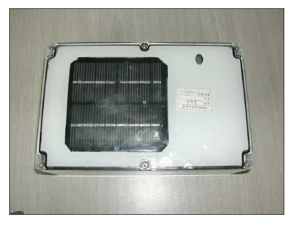
RG3WGPS900M01
Feb 15, 2006GPS Wireless Clock Systems Host
Equipment Class
DSS - Part 15 Spread Spectrum Transmitter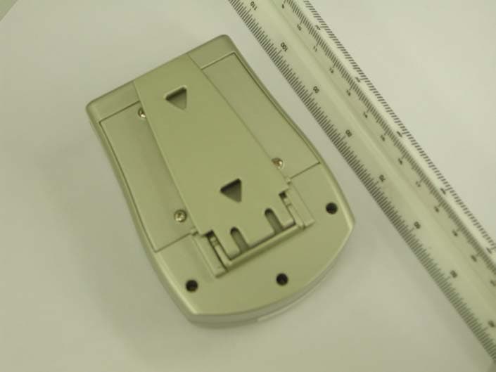
RG375320TX
Nov 18, 2003In/Out Thermometer w/ Radio-Controlled Clock
Equipment Class
DSC - Part 15 Security/Remote Control Transmitter