RIDBTA-804Bluetooth dongle
GlobalSat WorldCom Corporation
Click to zoom
Application Details
- Equipment Class
- DSS - Part 15 Spread Spectrum Transmitter
- Date of Grant
- Oct 01, 2003
- Application Purpose
- Original Equipment
- Date of Application
- Sep 28, 2003
- Equipment Note
- Bluetooth dongle
- Frequency Range
- 2402.00000000 - 2480.00000000
- Country
- Taiwan
Documents & Files
Document Text
Text extracted from the exhibit documents filed with the FCC. Open a document above to read the original.
Users Manual
BTW 1.4 User’s Guide , 2003 Document Number: (011107-1006-BTW_btw1.2_docs_BTWDocs.doc) Version: 1.4 BTW User’s Guide September 1 , 2003 Globalsat i LICENSED SOFTWARE © Copyright 2000 – 2003, WIDCOMM, Inc. (“WIDCOMM”). All rights reserved. Warning: This software and accompanying documentation are protected by copyright law and international treaties. Unauthorized reproduction or distribution of this software, or any portion of it, may result in severe civil and criminal penalties, and will be prosecuted to the maximum extent possible under the law. Use of this software is governed by the terms of the end user license agreement that accompanies or is included with such software. Unless otherwise noted in the end user license agreement, or herein, no part of the documentation accompanying this software, whether provided in printed or electronic form may be reproduced in any form, or stored in a database or retrieval system, or transmitted in any form or by any means, or used to make any derivative work (such as translation, transformation, or adaptation) without the express, prior written consent of WIDCOMM. Trademark(s) ™ and Registered Trademark(s) ® WIDCOMM and the WIDCOMM logo are trademarks of WIDCOMM, Inc. Bluetooth and the Bluetooth logos are trademarks owned by Bluetooth SIG, Inc., U.S.A. and licensed to WIDCOMM, Inc. Microsoft, Windows, Outlook are registered trademarks of Microsoft Corporation. Other brand and product names may be registered trademarks or trademarks of their respective holders. BTW User’s Guide September 1 , 2003 Globalsat ii Table of Contents 1 Introduction............................................................................................................ 1 1.1 Bluetooth Tray .................................................................................................................1 1.2 Access My Bluetooth Places............................................................................................ 1 1.3 Icons Used for Bluetooth Devices and Services .............................................................. 2 2 Basic Operations ................................................................................................... 5 2.1 Start or Stop Bluetooth..................................................................................................... 5 2.2 Create a Connection From the Bluetooth Icon in the System Tray ................................. 5 2.3 Create a Connection Using the Bluetooth Setup Wizard ................................................. 5 2.4 Create a Connection From Entire Bluetooth Neighborhood............................................ 5 2.5 Find Bluetooth Devices.................................................................................................... 6 2.5.1 Periodic Search for Devices ................................................................................. 6 2.6 Find A Service ................................................................................................................. 7 2.7 Bluetooth Connection Status............................................................................................ 8 2.8 Send to Bluetooth............................................................................................................. 9 3 Configure Bluetooth ............................................................................................ 10 3.1 Access the Bluetooth Configuration Panel .................................................................... 10 3.2 Bluetooth Services versus Bluetooth Applications ........................................................ 10 3.3 Bluetooth Exchange Folder............................................................................................ 10 3.4 General Configuration Settings...................................................................................... 11 3.5 Bluetooth Applications .................................................................................................. 11 3.5.1 Overview ............................................................................................................ 11 3.5.2 General Configuration ........................................................................................ 11 3.5.3 Human Interface Device..................................................................................... 12 3.5.4 Audio Gateway ................................................................................................... 13 3.5.5 Bluetooth Serial Port .......................................................................................... 14 3.5.6 Dial-up Networking............................................................................................ 15 3.5.7 Fax ...................................................................................................................... 16 3.5.8 Headset ............................................................................................................... 17 3.5.9 File Transfer ....................................................................................................... 18 3.5.10 Network Access.................................................................................................. 19 3.5.11 PIM Synchronization.......................................................................................... 20 3.5.12 PIM Item Transfer .............................................................................................. 22 3.5.13 Printer ................................................................................................................. 24 3.6 Bluetooth Services ......................................................................................................... 25 3.6.1 Notifications ....................................................................................................... 26 3.6.2 Audio Gateway .............................................................................…
Text truncated - open the document above for the full version.
Block Diagram
PCB Antenna Bluetooth Module GlobalSat BTM-001 Power Regulator (5V ~ 3.3V) LED (Blue) USB Power 5V Module: BTM-001
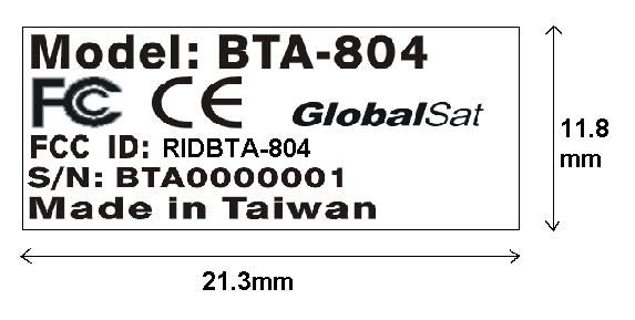
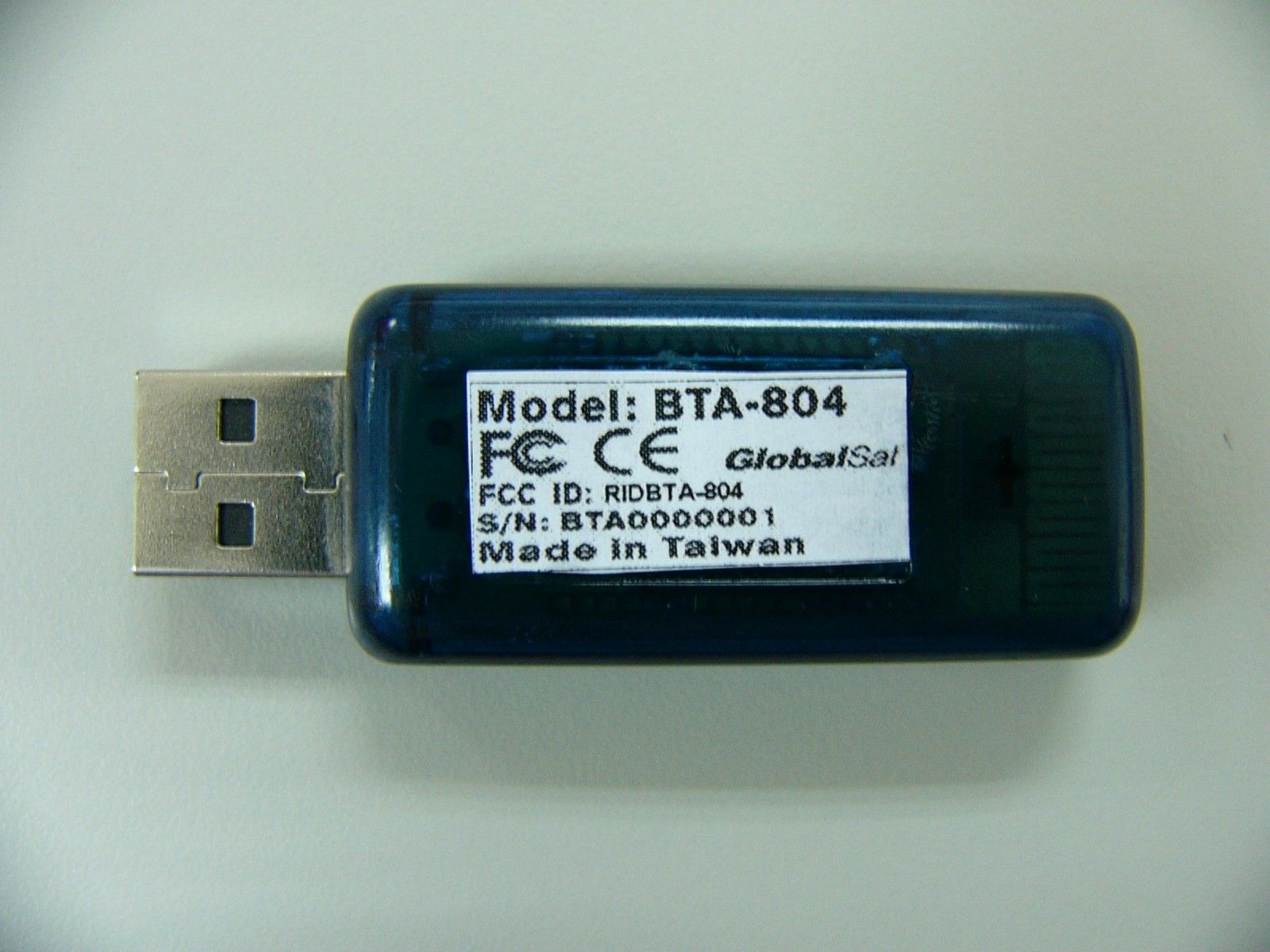
External Photos
External Photos
Internal Photos
Internal Photos
Operational Description
Operation description BTA-804 1. Purpose: The purpose of this document is to describe key component operations on Bluetooth. 2. Key components: BTM-001, GlobalSat Bluetooth Module calss II, XC6209B332MR High Speed LDO Regulators, 3. Operation Principle: GlobalSat BTM-001 Module class II, it provides a fully compliant Bluetooth system for data and voice communications. Operation at 2.7 ~ 3.3V supply. Operation clock is provided by 16MHz oscillator. Key Features Radio -Operation with common TX/RX terminals simplifies external matching circuitry and eliminates external antenna switch -Extensive built-in self-test minimizes production test time -No external trimming is required in production -Full RF reference designs are available Transmitter -Up to 0dBm RF transmit power with level control from the on-chip 6-bit DAC over a dynamic range greater than 30dB -Supports Class 2 and Class 3 radios without the need for an external power amplifier or TX/RX switch Receiver -Integrated channel filters -Digital demodulator for improved sensitivity and co-channel rejection -Digitized RSSI available in real time over the HCI interface -Fast AGC for enhanced dynamic range Synthesizer -Fully integrated synthesizer, no external VCO varactor diode or resonator -Compatible with crystals between 8 and 32MHz (in multiples of 250KHz) or an external clock Auxiliary Features -Crystal oscillator with built-in digital trimming -Power management includes digital shut down and wake up commands and an integrated low power oscillator for ultra-low Park/Sniff/Hold mode power consumption -Devices can be used with an external Master oscillator and provides a clock request signal. To control external clock source. -Uncommitted 8-bit ADC and 8-bit DAC are available to application programs Baseband and software -External 8Mbit flash for complete system solution and application flexibility -32kbyte on-chip RAM allows full speed Bluetooth data transfer, mixed voice and data, plus full 7 slaves Pico net operation -Dedicated logic for forward error correction, header error control, access code correlation, demodulation, cyclic redundancy check, encryption bit-stream generation, whitening and transmit pulse shaping -Transponders for A-law, μ-law and linear voice rom host and A-law, μ-law and CVSD voice over air Physical Interfaces -Synchronous serial interface up to 4MBaud -UART interface with programmable Baud rate up to 1.5MBaud -Full speed USB interface supports OHCI and UHCI host interfaces. Compliant with USB v1.1 -Synchronous bi-directional serial programmable audio interface -Operational l-CTM Compatible interface Bluetooth Stack Running on an Internal Micro-controller CSR.s Bluetooth Protocol Stack runs on-chip in a variety of configurations: -Standard HCI (UART or USB) -Fully embedded to RFCOMM, thus reducing host CPU load XC6209B332MR, High Speed LDO Regulators The XC6209 series are highly precise, low noise, positive voltage LDO regulators Maximum Output Current: 200mA manufactured using CMOS processes. The series achieves high ripple rejection Dropout Voltage: 200mV (IOUT = 100mA) and low dropout and consists of a standard voltage source, an error correction, Maximum Operation Voltage: 10V current limiter and a phase compensation circuit plus a driver transistor. Output Voltage Range: 0.9V - 6.0V in 50mV increments Output voltage is selectable in 50mV increments within a range of 0.9V ~ 6.0V. Highly Accurate: ±2% the series is also compatible with low ESR ceramic capacitors which give added Low Power Consumption: TYP 25μA output stability. This stability can be maintained even during load fluctuations due Standby Current: less than 0.1μA to the excellent transient response of the series. High ripple Rejection : 70dB (10kHz) The Current limiter’s feedback circuit also operates as a short protect for the output Low Output Noise: 30μVrms current limiter and the output pin. Operating Temperature Range: -40°C ~ +85 °C The CE function enables the output to be turned off, resulting in greatly reduced Low ESR Capacitor Compatible : Ceramic capacitor power consumption.
Schematics
55 44 33 22 11 D D C C B B A A L1、L2=L0603L1206 USB-Dongle 1.1 <Title> A 11 Wednesday, August 13, 2003 TitleSize Document Number Rev Date: Sheet of VDD VDD 3V3 DPDN VDD DMDP 3V3 U2 XC6209B332MR 53 2 41 OUT EN GND BYPVIN R5 470R L2 FB R2 10R R7 1K R1470R D1Red 21 L1 FB D2 GREEN 2 1 C30.1u C50.1u C40.1u + C210u/10V 12 ANT1ANTENNA + C122u/16V 12 D3 Blue 2 1 R41K5 R6 470R U1 BTM-001 532416789 1011121314151617 1819202122232425262728293031323334 AIO-1GND_PAVDD_PAAIO-0GNDRESETSPI_MISOSPI_CSBSPI_CLKSPI_MOSICTSTXRTSRX1V83V3GND PCM_OUT PCM_SYNC PCM_IN PCM_CLK USB_DP USB_DN PIO-7PIO-6PIO-5PIO-4PIO-3PIO-2PIO-1PIO-0 GND ANT-RF GND L4 FB R3 10R CON1 USB-A-4P 1432 csr Cambridge Science Park, Milton Road Cambridge, CB4 0WH, United Kingdom. Tel. +44 (0)1223 692000 Fax. +44 (0)1223 692001 http://www.csr.com R422R J5 J6 J13 J11 J14 J22 J10 J7 J21 J20 J19 J31 J30 J28 J27 J25 J24 J1 J17 J16 J15 C1 47p +1V8 C3 1p8 3n9 L2 C7 220p (COG) C4 10n C5 10n +1V8+1V8 2u2 C8 R3 0R +3V3 C13 10n C10 10n +3V3 +1V8 +1V8 C16 100n R7 1K 2u2 C14 J4 J23 J12 J18 J9 J8 J29 J26 J3 J2 4 OUT 1 IN 2 GND 3 GND MDR741F U3 3n9 L3 1p8 C2 R2 180K +1V8 VMEM +1V8 16MHz X1 +1V8 J34 J32 TP2 J33 TP1 C6 NF NF R1 L1 3n9 R6 0R0 VMEM C9 47p 3p3 C11 VMEM C15 100n R5 22R 10p C12 +3V3 2 GND 3 CE 4 NC 1 Vin 5 Vout XC6204B182MR U4 54 123 6 N/C T1 HHM-1517 G4 VCC H1 VSS F6 B YTE F1 CE C3 A18 D6 A15 B6 A12 A5 A9 C2 A6 A1 A3 E1 A0 D4 A19 H6 VSS A4 WE G1 OE B4 RESET A2 A7 B5 A8 C5 A10 D5 A11 A6 A13 C6 A14 E6 A16 D1 A1 C1 A2 B1 A4 B2 A17 D2 A5 D3 NC A3 RY/BY F4 DQ12 G2 DQ9 H5 DQ6 H3 DQ3 E2 DQ0 B3 NC C4 NC E5 DQ7 F2 DQ8 F3 DQ10 G3 DQ11 G5 DQ13 F5 DQ14 H2 DQ1 E3 DQ2 H4 DQ4 E4 DQ5 G6 DQ15A-1 U2 AM29LV800B D10 REB E9 A[1] F10 A[4] G10 A[7] L9 D[1] L8 D[4] L7 D[7] J2 VSS_VCO K1 VDD_ANA F2 VSS_RADIO A9 VSS_CORE D1 VDD_RADIO C11 VSS_MEM A10 VDD_PADS H10 A[10] J9 A[13] K9 A[16] L1 XTAL_IN L6 D[10] L5 D[13] C7 VSS C10 CSB E11 A[2] E10 WEB D9 A[0] F11 A[5] G11 A[8] H9 A[9] G9 A[6] L10 D[2] J7 D[5] K8 D[0] L11 D[3] J6 D[8] K6 D[9] G2 VSS_RADIO A11 VSS_PADS L3 VSS_ANA E2 VSS_RADIO H3 VDD_RADIO A1 VDD_PIO H1 VDD_VCO H11 A[11] J10 A[14] J8 A[12] A8 VDD_CORE D11 VDD_MEM K10 A[17] K11 A[18] J5 D[11] J4 D[14] K5 D[12] K4 D[15] L2 XTAL_OUT J3 AIO[2] G3 TEST_EN B6 UART_CTS B4 SPI_MISO B8 PCM_CLK B11 PCM_SYNC C2 PIO[1] B1 PIO[4] E3 PIO[7] C5 PIO[10] F9 A[3] J1 LOOP_FILTER H2 VSS_VCO D2 AUX_DAC G1 TX_A F1 TX_B E1 RF_IN K7 D[6] F3 RESET B7 UART_RTS C9 UART_RX C8 UART_TX L4 AIO[1] A7 USB_D+ A5 SPI_MOSI B10 PCM_IN A4 SPI_CSB B5 SPI_CLK B9 PCM_OUT C4 PIO[9] D3 PIO[8] C3 PIO[6] A3 PIO[5] B2 PIO[3] B3 PIO[2] C1 PIO[0] A2 VSS_PIO J11 A[15] A6 USB_D- K3 AIO[0] K2 VSS_ANA C6 PIO[11] U1 BC212015ADN-E4
Test Report
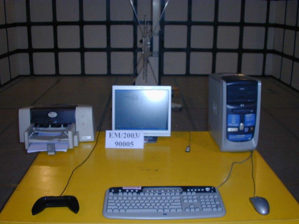
Report No. : ER/2003/90003 Page : 1 of 47 TEST REPORT Equipment Under Test : Globalsat Bluetooth Dongle Model No. : BTA-804 Applicant : Globalsat Technlogy Corporation 2-1F,No 16,Chien 8 Rd,Far East Century Park,Chung Ho City ,Taipei Hsien 235 Taiwan , R.O.C. Address of Applicant : Standards: FCC Part 15 subpart C In the configuration tested, the EUT complied with the standards specified above. Remarks: This report details the results of the testing carried out on one sample, the results contained in this test report do not relate to other samples of the same product. The manufacturer should ensure that all products in series production are in conformity with the product sample detailed in this report. This report may only be reproduced and distributed in full. If the product in this report is used in any configuration other than that detailed in the report, the manufacturer must ensure the new system complies with all relevant standards. Any mention of SGS Taiwan E&E Services or testing done by SGS Taiwan E&E Services in connection with distribution or use of the product described in this report must be approved by SGS Taiwan E&E Services in writing. Tested by : Alex Hsieh Date : Sep. 9, 2003 Approved by : Robert Chang Date : Oct. 2, 2003 Report No. : ER/2003/90003 Page : 2 of 47 Contents 1. General Information 1.1 Testing Laboratory 3 1.2 Details of Applicant 3 1.3 Description of EUT(s) 3 1.4 Operation Procedure 4 1.5 Testing Method 4 2. Summary of Results 6 3. Instruments List 7 4. Measurements 8 4.1 Conducted emission Limits 8 4.2 Radiated emission Limits, general requirement 11 4.3 Channel Spacing 18 4.4 20db bandwidth / No. of channels 19 4.5 Average time of Occupancy 24 4.6 Peak output power 28 4.7 Band-edge emission 31 4.8 Spurious Emission under 25Ghz 33 APPENDIX Photographs of Test Setup 45 Photographs of EUT 46-47 Report No. : ER/2003/90003 Page : 3 of 47 1. General Information 1.1 Testing Laboratory SGS Taiwan Ltd. ( FCC Registration number: 573967 ) 1F, No. 134, Wukung Road, Wuku industrial zone Taipei county , Taiwan , R.O.C. Telephone : +886-2-2299-3279 Fax : +886-2-2298-2698 Internet : http://www.sgs.com.tw 1.2 Details of Applicant Applicant : Globalsat Technology Corporation Address of Applicant: 2-1F,No 16,Chien 8 Rd,Far East Century Park,Chung Ho City,Taipei Hsien 235 Taiwan , R.O.C. Contact: Ray Tsai Telephone: +886-2-82263799 ext.206 1.3 Description of EUT(s) 1 Product name Globalsat Bluetooth Dongle 2 Product ID BTA-804 3 Supply Voltage DC 5.0V from USB 4 Antenna Gain 0 dbi 5 Carrier Frequency 2402MHz to 2480MHz 6 Modulation Method GFSK,1Mbps,0.5BT Gaussian 7 Hopping 1600hops/sec, 1MHz channel space 8 Output Interface USB 9 Operation Temperature -20 to +55 degree 10 Compliant Bluetooth Specification Ver1.1 Report No. : ER/2003/90003 Page : 4 of 47 1.4 Operation Procedure The Bluetooth is a FHSS system, and the output power and operating frequency are NOT End-user adjustable. Applicant offer a engineering software “BlueSuite” installed on PC to control the EUT. Setting of the software parameters are set as default. Operating frequency are set as testing required. The output power is set as Ext=255, Int=60 (at max. power). Inside the BlueSuite software, there is a BlueTest to control EUT hopping on or off. We select “Txdata1” (which modulated by pseudo-random sequence)and assign the transmit channel(as below). When the EUT is required to transmit in hopping on mode. We select “Txdata2” The lowest operating frequency within Bluetooth specification is 2402Mhz, and highest operating frequency is 2480Mhz. So the frequency above are used as the lowest and highest frequency in the testing, and the middle frequency is set as 2441Mhz. 1.5 Testing Method The testing standard follows CFR 47, Part 15.247 and ANSI C63.4 1992, and measurement method according to Public Notice DA00-705 (March 2000). The Testing procedure is as following: a. The EUT was plug in the USB port of PC and placed on the top of a rotating table 0.8 meters above the ground at a 3m chamber. The table was rotated 360 degrees to determine the position of the highest radiation. b. The EUT was set 3 meters away from the interference-receiving antenna. c. The antenna is a broadband antenna, and its height is varied from one meter to four meters above the ground to determine the maximum value of the field strength. Both horizontal and vertical polarizations of the antenna are set to make the measurement. d. For each suspected emission, the EUT was arranged to its worst case and then the antenna was tuned to heights from 1 meter to 4 meters and the turn table was turned from 0 degrees to 360 degrees to find the maximum reading. e. The test-receiver system was set to Peak Detect Function and Specified Bandwidth with Maximum Hold Mode. Report No. : ER/2003/90003 Page : 5 of 47 NOTE: 1. The resolution bandwidth and video bandwidth of test receiver/spectrum analyzer is 120kHz for Peak detection (PK) and Quasi-peak detection (QP) at frequency below 1GHz. 2. The resolution bandwidth and video bandwidth of test receiver/spectrum analyzer is 1 MHz for Peak detection at frequency above 1GHz. 3. The resolution bandwidth of test receiver/spectrum analyzer is 1 MHz and the video bandwidth is 300 Hz for Average detection (AV) at frequency above 1GHz. 4. During the Output power testing, the manufacturer attach a test fixture which is a short cable that replace the antenna. So we use conducted method to measure the power. Hence the EIRP is the output power plus the antenna gain in dBi. Due to cable loss, the real value will equal to measured value(show on the instrument) add cable loss. Report No. : ER/2003/90003 Page : 6 of 47 2.Summary of Results subclause Parameter to be measures Verdict Page 15.207 Conducted emission Limit PASS 8 15.209 Radiated emission Limits, general requirement PASS 11 15.247(a)(1) Channel Spacing PASS 18 15.247(a)(1)(ii) 20db bandwidth / No. of channels PASS 19 15.247(a)(1)(ii) Average Time of Occupancy …
Text truncated - open the document above for the full version.
Contact Information
Applicant
Ray Tsai(Director)
Test Firm
SGS Taiwan Ltd.Wyse Chiu
Technical Specifications
| # | Rule Parts | Frequency Range | Power Output |
|---|---|---|---|
| 1 | 15C | 2.40 GHz - 2.48 GHz | 580.00 µW |
Other Applications from GlobalSat WorldCom Corporation

RID-MDPANIC
Jun 07, 2020Personal Tracker
Equipment Class
DTS - Digital Transmission System
RID-GH209
Jan 03, 20163 in 1 Training Watch
Equipment Class
DTS - Digital Transmission System
RID-TW100
Dec 24, 2015Wearable Watch Tracker
Equipment Class
PCF - PCS Licensed Transmitter held to face
RID-LR101H
Nov 23, 2015LoRa Wireless Module
Equipment Class
DTS - Digital Transmission System
RID-TR300V
Sep 12, 2015Personal Tracker
Equipment Class
PCF - PCS Licensed Transmitter held to face