RIM-ICCUConcentration and Communications Unit
FB iMonitoring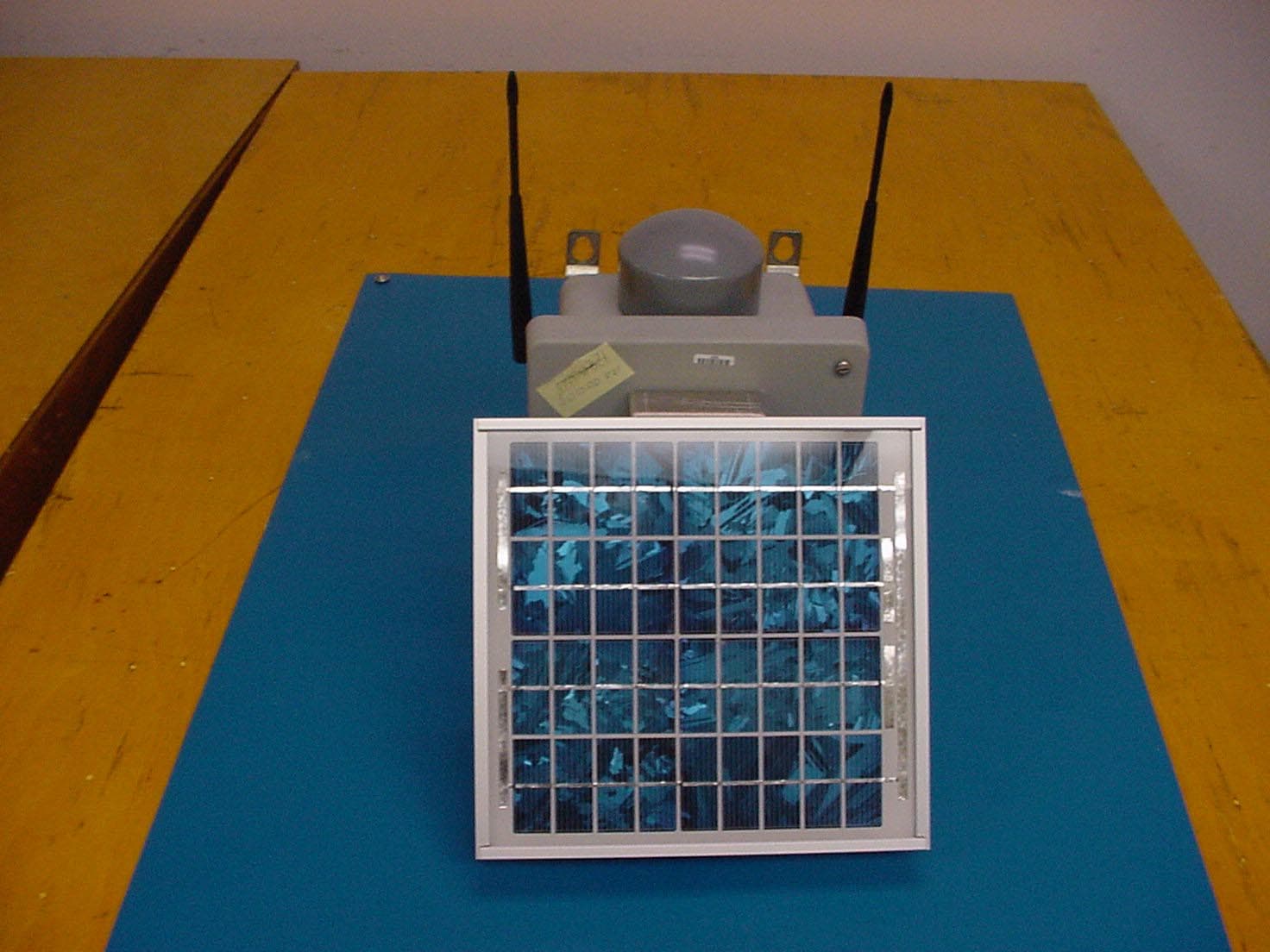
Click to zoom
Application Details
- Equipment Class
- DSS - Part 15 Spread Spectrum Transmitter
- Date of Grant
- Dec 16, 2003
- Application Purpose
- Original Equipment
- Date of Application
- Dec 11, 2003
- Equipment Note
- Concentration and Communications Unit
- Frequency Range
- 902.49140000 - 927.76950000
- Company
- FB iMonitoring
- Country
- United States
Documents & Files
Document Text
Text extracted from the exhibit documents filed with the FCC. Open a document above to read the original.
Users Manual
Oil & Gas Wireless Enabled Monitoring System Installer’s Guide 2 Oil & Gas Wireless Enabled Monitoring System Installer’s Guide Document version B.2 © 2003 Luna iMonitoring, Inc. 2903 Commerce Street, Suite A Blacksburg, VA 24060 Phone: 540.557.5880 Fax: 540.951.0760 E-mail: [email protected] Web: www.lunaimonitoring.com No portion of this publication may be reproduced or transmitted by any means without the written permission of Luna iMonitoring, Inc. i Contents 1 Introduction................................................................................................... 1 The Intelligent Wireless Sensor Suite ................................................................................... 2 WEMS Components ............................................................................................................... 2 Concentration and Communications Unit (iCCU) ...........................................................................3 Compact Flash Radio (iCFR) ........................................................................................................3 Electronic Flow Monitor (iEFM) ....................................................................................................4 Tank Level Monitor (iTLM-1) .......................................................................................................4 Wellhead Pressure Monitor (iWPM-T) ...........................................................................................5 Secure Digital (SD) Card..............................................................................................................5 User-supplied Components ................................................................................................... 5 2 Installation .................................................................................................... 6 Site Selection for WEMS Components ................................................................................... 6 Guidelines Concerning RF Signal Transmission ..............................................................................6 Guidelines Concerning Solar Panels ..............................................................................................8 Guidelines Concerning Hazardous Environments ...........................................................................8 Guidelines Concerning iTLM-1 Mounting.......................................................................................8 Pre-installation iTLM-1 Depth Calibration ............................................................................ 9 Installation Instructions .......................................................................................................9 Monitor Installation Instructions...................................................................................................9 iCCU Installation Instructions ....................................................................................................10 iCFR Installation Instructions .....................................................................................................11 3 WEMS Software ........................................................................................... 12 Installing the WEMS Software ............................................................................................ 12 PocketConfig ....................................................................................................................... 15 Adding New Devices..................................................................................................................16 WEMS Installer’s Guide Contents ii Sensor Charge Modes................................................................................................................17 Setting the Default ReSync Time................................................................................................17 Finding Sleeping Devices ...........................................................................................................18 About PocketConfig ...................................................................................................................19 Configuration Menus .................................................................................................................21 Uplink Scheduling Menu ............................................................................................................24 Update Flash Menu ...................................................................................................................26 Sensor Data Menu................................................................................................................... 279 iCCU-Specific Menus .................................................................................................................30 iCCU Uplink Menu .................................................................................................................................................... 30 iCCU Status Menu .................................................................................................................................................... 31 iEFM-Specific Menus .................................................................................................................32 iEFM Sensor Calibration ............................................................................................................................................ 32 iEFM Gas Calibration ................................................................................................................................................ 33 iEFM Sensor Data..................................................................................................................................................... 34 iTLM-1-Specific Menus ..................................................................................…
Text truncated - open the document above for the full version.
Cover Letter(s)
American Telecommunications Certification Body Inc. 6731 Whittier Ave, McLean, VA 22101 November 11, 2003 RE: Luna iMonitoring FCC ID: RIM-ICCU I have a few comments on the above referenced Application. 1) Please provide photographs to show the placement of the part 25 Module, as well as top/bottom photographs of this module (with and without shields). Response : Please refer to the revised internal photograph exhibit uploaded with this response. 2) The users manual mentions that the device is field programmable and upgradeable, while a cover letter mentions only professional installation. Who has access to the software for the device. The software for connection to the device appears to show adjustment for various TX power levels and AMP power modes (page 27). Page 28 of the users manual also shows a test mode that allows the device to be hop-stopped. The end user should not have access to such control of the device (15.15(b)). Please explain. Response : Please refer to the revised manual uploaded with this response, and note the following: a) Concerning the field programmable statement: Only the installer has access to the software mentioned. The statement “field programmable and upgradeable” has been changed to “installer programmable and upgradeable”. The descriptions of the CFR, EFM, TLM on page 4 and the WPM on page 5 have been changed to reflect this. b) Concerning the power and amp levels: The CFR description on page 4 has been changed to the following: Other features include programmable output power to an upper limit as defined in Appendix A, low cost, and the ability to configure and upgrade the unit by the installer. The following has been added to the Configuration Menu Description on page 22: The AmpSetting and XmitPower controls are available only to reduce the power below the authorized limits stated Appendix A of this document when desired, the controls will not allow power greater than the authorized limits. 3) Please explain the derivation of limits 95.9, 78.7, 97.1, 82.2, 96.2, 80.4 given in tables 9-2 through 9-4. These do not appear to be based on the results of the fundamental - 20 dB from section 6 of the report. Response : The tables have been corrected. The limit is based on 20 dB below the carrier. Since the unit has a bandwidth around 100 Khz, and the band edge plots are taken at 30 Khz, the level shown on the Band Edge would be lower. American Telecommunications Certification Body Inc. 6731 Whittier Ave, McLean, VA 22101 4) The levels in 6 of the report do not appear to correlate to the power reported for this device. Please explain. Response : The plots listed in part 6 represent the maximum field strength found on the open site. Meanwhile the calculation would give a worst-case value of what the EIRP should be. The maximum calculated EIRP would be 0.09 W based on the field strength value, where the power output plus the antenna gain give us 0.078W. 5) The users manual (page 49) mentions an output power of 17.4 dBm nominal, while the maximum power tested was 17.0 dBm. Note that the preferred method for measurement of this signal would be a Spectrum analyzer with VBW>= RBW >= 20 dB bandwith (prefer RBW = 1 MHz or greater). Please explain and/or correct affected exhibits. Response : The power measurement was performed with a power meter and was checked with the appropriate settings on a spectrum analyzer. 6) The results of 4639 MHz given in Table 9-4 do fall in a restricted band and are subject to the limits of 54 dBuV/m. Please correct. Response : Please refer to the revised test report uploaded with this response. 7) For purposes of Average measurements in section 9.3, please verify that the carrier was hop stopped and non-pulsing during these tests. If the device was not appropriately hop stopped with a non-pulsing carrier, then the use of the AVG detector using standard RBW = 1 MHz and VBW = 10 Hz may not be allowed. Response : The unit was set to a mode where the hop was stopped, and with a non-pulsing carrier, which allowed us to perform an average measurement. 8) Please explain compliance of the EUT to 15.247(g)/(h) and 2.1033(b)(10). Response : Please refer to the revised FHSS description uploaded with this response. 9) There have been multiple changes to part 25 recently. It may be possible that the TX may now be required to be certified. We are investigating these changes and will let you know what we determine as soon as we can. Response: The client is aware that there have been multiple changes to Part 25, but needs to have this product certified as the rules stand today, in order to meet business commitments. Please advise us of the definitive FCC responses once you receive them, so that the client can maintain and ensure continued compliance. Timothy R. Johnson Examining Engineer mailto: [email protected] The items indicated above must be submitted before processing can continue on the above referenced application. Failure to provide the requested information may result in application termination. Correspondence should be considered part of the permanent submission and may be viewed from the Internet after a Grant of Equipment Authorization is issued. Please do not respond to this correspondence using the email reply button. In order for your response to be processed expeditiously, you must submit your documents through the AmericanTCB.com website. Also, please note that partial responses increase processing time and should not be submitted. Any questions about the content of this correspondence should be directed to the sender.
Cover Letter(s)
Rhein Tech Laboratories, Inc. Client: Luna iMonitoring 360 Herndon Parkway Model Name: iCCU Suite 1400 FCC ID: RIM-ICCU FCC: 15.247 Herndon, VA 20170 http://www.rheintech.com IC: RSS-210 Page 35 of 53 APPENDIX C: AGENCY AUTHORIZATION LETTER Please refer to the following page.
Cover Letter(s)
Rhein Tech Laboratories, Inc. Client: Luna iMonitoring 360 Herndon Parkway Model Name: iCCU Suite 1400 FCC ID: RIM-ICCU FCC: 15.247 Herndon, VA 20170 http://www.rheintech.com IC: RSS-210 Page 36 of 53 APPENDIX D: CONFIDENTIALITY REQUEST LETTER Please refer to the following page.
Cover Letter(s)
Rhein Tech Laboratories, Inc. Client: Luna iMonitoring 360 Herndon Parkway Model Name: iCCU Suite 1400 FCC ID: RIM-ICCU FCC: 15.247 Herndon, VA 20170 http://www.rheintech.com IC: RSS-210 Page 37 of 53 APPENDIX E: PROFESSIONAL INSTALLATION ATTESTATION Please refer to the following page.
Cover Letter(s)
American Telecommunications Certification Body Inc. 6731 Whittier Ave, McLean, VA 22101 November 11, 2003 RE: Luna iMonitoring FCC ID: RIM-ICCU I have a few comments on the above referenced Application. 1) Please provide photographs to show the placement of the part 25 Module, as well as top/bottom photographs of this module (with and without shields). 2) The users manual mentions that the device is field programmable and upgradeable, while a cover letter mentions only professional installation. Who has access to the software for the device. The software for connection to the device appears to show adjustment for various TX power levels and AMP power modes (page 27). Page 28 of the users manual also shows a test mode that allows the device to be hop-stopped. The end user should not have access to such control of the device (15.15(b)). Please explain. 3) Please explain the derivation of limits 95.9, 78.7, 97.1, 82.2, 96.2, 80.4 given in tables 9-2 through 9-4. These do not appear to be based on the results of the fundamental - 20 dB from section 6 of the report 4) The levels in 6 of the report do not appear to correlate to the power reported for this device. Please explain. 5) The users manual (page 49) mentions an output power of 17.4 dBm nominal, while the maximum power tested was 17.0 dBm. Note that the preferred method for measurement of this signal would be a Spectrum analyzer with VBW >= RBW >= 20 dB bandwith (prefer RBW = 1 MHz or greater). Please explain and/or correct affected exhibits. 6) The results of 4639 MHz given in Table 9-4 do fall in a restricted band and are subject to the limits of 54 dBuV/m. Please correct. 7) For purposes of Average measurements in section 9.3, please verify that the carrier was hop stopped and non- pulsing during these tests. If the device was not appropriately hop stopped with a non-pulsing carrier, then the use of the AVG detector using standard RBW = 1 MHz and VBW = 10 Hz may not be allowed. 8) Please explain compliance of the EUT to 15.247(g)/(h) and 2.1033(b)(10). 9) There have been multiple changes to part 25 recently. It may be possible that the TX may now be required to be Certified. We are investigating these changes and will let you know what we determine as soon as we can. Timothy R. Johnson Examining Engineer mailto: [email protected] The items indicated above must be submitted before processing can continue on the above referenced application. Failure to provide the requested information may result in application termination. Correspondence should be considered part of the permanent submission and may be viewed from the Internet after a Grant of Equipment Authorization is issued. Please do not respond to this correspondence using the email reply button. In order for your response to be processed expeditiously, you must submit your documents through the AmericanTCB.com website. Also, please note that partial responses increase processing time and should not be submitted. Any questions about the content of this correspondence should be directed to the sender.
External Photos
Rhein Tech Laboratories, Inc. Client: Luna iMonitoring 360 Herndon Parkway Model Name: iCCU Suite 1400 FCC ID: RIM-ICCU FCC: 15.247 Herndon, VA 20170 http://www.rheintech.com IC: RSS-210 Page 47 of 53 APPENDIX M: EXTERNAL PHOTOGRAPHS PHOTOGRAPH 4: iCCU FRONT Rhein Tech Laboratories, Inc. Client: Luna iMonitoring 360 Herndon Parkway Model Name: iCCU Suite 1400 FCC ID: RIM-ICCU FCC: 15.247 Herndon, VA 20170 http://www.rheintech.com IC: RSS-210 Page 48 of 53 PHOTOGRAPH 5: iCCU REAR
ID Label/Location Info
Rhein Tech Laboratories, Inc. Client: Luna iMonitoring 360 Herndon Parkway Model Name: iCCU Suite 1400 FCC ID: RIM-ICCU FCC: 15.247 Herndon, VA 20170 http://www.rheintech.com IC: RSS-210 Page 40 of 53 APPENDIX H: LABEL AND LABEL LOCATION Please see the following pages for a sample of the FCC and Industry Canada Identification Label, and label location. Model: SN: CCU12800000 1.53X2.69 i Monitoring 9KA7 This device complies with Part 15 of the FCC rules. Operation is subject to the following two conditions: (1) This device will not cause harmful interference and (2) This device must accept any interference received, including interference that may cause undesired operation. RIM-ICCU FCC ID: Phone 1-540-557-5880 www.lunaimonitoring.com 4747A-ICCU IC: Rhein Tech Laboratories, Inc. Client: Luna iMonitoring 360 Herndon Parkway Model Name: iCCU Suite 1400 FCC ID: RIM-ICCU FCC: 15.247 Herndon, VA 20170 http://www.rheintech.com IC: RSS-210 Page 41 of 53 PHOTOGRAPH 1: FCC ID LABEL LOCATION ON FRONT OF EUT FCC ID LABEL LOCATION
Internal Photos
Rhein Tech Laboratories, Inc. Client: Luna iMonitoring 360 Herndon Parkway Model Name: iCCU Suite 1400 FCC ID: RIM-ICCU FCC: 15.247 Herndon, VA 20170 http://www.rheintech.com IC: RSS-210 Page 49 of 56 APPENDIX N: INTERNAL PHOTOGRAPHS PHOTOGRAPH 6: VIEW INTO ENCLOSURE Rhein Tech Laboratories, Inc. Client: Luna iMonitoring 360 Herndon Parkway Model Name: iCCU Suite 1400 FCC ID: RIM-ICCU FCC: 15.247 Herndon, VA 20170 http://www.rheintech.com IC: RSS-210 Page 50 of 56 PHOTOGRAPH 7: PCB FRONT WITH SHIELD Rhein Tech Laboratories, Inc. Client: Luna iMonitoring 360 Herndon Parkway Model Name: iCCU Suite 1400 FCC ID: RIM-ICCU FCC: 15.247 Herndon, VA 20170 http://www.rheintech.com IC: RSS-210 Page 51 of 56 PHOTOGRAPH 8: PCB FRONT WITHOUT SHIELD Rhein Tech Laboratories, Inc. Client: Luna iMonitoring 360 Herndon Parkway Model Name: iCCU Suite 1400 FCC ID: RIM-ICCU FCC: 15.247 Herndon, VA 20170 http://www.rheintech.com IC: RSS-210 Page 52 of 56 PHOTOGRAPH 9: PCB REAR WITH SHIELD Rhein Tech Laboratories, Inc. Client: Luna iMonitoring 360 Herndon Parkway Model Name: iCCU Suite 1400 FCC ID: RIM-ICCU FCC: 15.247 Herndon, VA 20170 http://www.rheintech.com IC: RSS-210 Page 53 of 56 PHOTOGRAPH 10: PCB REAR WITHOUT SHIELD Rhein Tech Laboratories, Inc. Client: Luna iMonitoring 360 Herndon Parkway Model Name: iCCU Suite 1400 FCC ID: RIM-ICCU FCC: 15.247 Herndon, VA 20170 http://www.rheintech.com IC: RSS-210 Page 54 of 56 PHOTOGRAPH 11: LOCATION OF PART 25 MODULE Part 25 Module Rhein Tech Laboratories, Inc. Client: Luna iMonitoring 360 Herndon Parkway Model Name: iCCU Suite 1400 FCC ID: RIM-ICCU FCC: 15.247 Herndon, VA 20170 http://www.rheintech.com IC: RSS-210 Page 55 of 56 PHOTOGRAPH 12: PART 25 MODULE TOP Rhein Tech Laboratories, Inc. Client: Luna iMonitoring 360 Herndon Parkway Model Name: iCCU Suite 1400 FCC ID: RIM-ICCU FCC: 15.247 Herndon, VA 20170 http://www.rheintech.com IC: RSS-210 Page 56 of 56 PHOTOGRAPH 13: PART 25 MODULE BOTTOM
RF Exposure Info
Rhein Tech Laboratories, Inc. Client: Luna iMonitoring 360 Herndon Parkway Model Name: iCCU Suite 1400 FCC ID: RIM-ICCU FCC: 15.247 Herndon, VA 20170 http://www.rheintech.com IC: RSS-210 Page 33 of 53 APPENDIX A: FCC PART 1.1307, 1.1310, 2.1091, 2.1093 RF EXPOSURE Two identical antennas are used with the device (Nearson S467FL-L-RMM-915S). Both antennas will never transmit simultaneously. The EUT also contains an Axonn LLC G-SENS STU satellite transceiver that is subject to Part 15 and Part 25 verification. US Tech performed this testing in August 2002 (see results for exposure below). Both Nearson antennas are located at the same distance from the satellite transceiver. From FCC 1.1310 Table 1B, the maximum permissible RF exposure for an uncontrolled environment for a device operating in the frequency band 902 – 928 MHz is 0.60 mW/cm 2 (calculation based on 902 MHz). The actual power density for the EUT and single antenna option is calculated as shown below. As shown by the calculation and table below, the EUT meets this requirement. )4/()( 2 dGPS×××=π where: S = power density P = transmitter conducted power in (W) G = antenna numeric gain d = distance to radiation center (m) Antenna Manufacturer Antenna Type Antenna Model Gain (dBi) Numeric Gain Power (W) Separation Distance (m) Power Density (mW/cm 2 ) Power Density Ratio compared to limit Nearson half wave dipole S467AH- 915S 2.0 1.585 0.050 0.03 0.016 2.6% Antenna Manufacturer Antenna Type Antenna Model Gain (dBi) Numeric Gain Power (W) Separation Distance (m) Power Density (mW/cm 2 ) Power Density Ratio compared to limit Axonn LLC G- SENS STU N/A N/A 4 2.51 0.146 0.056 0.073 7.3% Therefore for collocation, the total ratios/limits = 9.9%.
Test Report
Engineering and Testing for EMC and Safety Compliance 360 Herndon Parkway, Suite 1400 Herndon, VA 20170 Phone: 703-689-0368; Fax: 703-689-2056; Metro: 703-471-6441 CERTIFICATION APPLICATION REPORT FCC PART 15.247 & INDUSTRY CANADA RSS-210 Test Lab: Rhein Tech Laboratories, Inc. Phone: 703-689-0368 360 Herndon Parkway Fax: 703-689-2056 Suite 1400 Web Site: www.rheintech.com Herndon, VA 20170 E-Mail: [email protected] Applicant: Luna iMonitoring Phone: 540-558-1692 Contact: Roger Secrest Fax: 540-951-0760 2851 Commerce Street E-Mail: [email protected] Blacksburg, VA 24060 FCC ID: RIM-ICCU GRANTEE FRN NUMBER: 0009610718 PLAT FORM: N/A RTL WORK ORDER NUMBER: 2003154 MODEL NUMBER / NAME: iCCU RTL QUOTE NUMBER: QRTL03-971A DATE OF TEST REPORT: November 4, 2003 American National Standard Institute: ANSI C63.4: Methods of Measurement of Radio-Noise Emissions from Low-Voltage Electrical and Electronic Equipment in the Range of 9 kHz to 40 GHz FCC Classification: DSS – Part 15 Spread Spectrum Transmitter Frequency Hopping FCC Rule Part(s): Part 15.247: Operation within the bands 902-928 MHz, 2400-2483.5 MHz and 5725-5850 MHz Frequency Hopping System Industry Canada Standard: RSS-210: Low Power License-Exempt Radio Communication Devices (All Frequency Bands) Digital Interface Information Digital Interface was found to be compliant Receiver Information Receiver was found to be compliant Frequency Range (MHz) Output Power* (W) Frequency Tolerance Emission Designator 902 – 928 0.05 N/A N/A * output power is maximum peak conducted We, the undersigned, hereby declare that the equipment tested and referenced in this report conforms to the identified standard(s) as described in this test report. Furthermore, there was no deviation from, additions to, or exclusions from the FCC Part 2, FCC Part 15, Industry Canada RSS-210, and ANSI C63.4 Signature: Date: November 4, 2003 Typed/Printed Name: Desmond A. Fraser Position: President Rhein Tech Laboratories, Inc. Client: Luna iMonitoring 360 Herndon Parkway Model Name: iCCU Suite 1400 FCC ID: RIM-ICCU FCC: 15.247 Herndon, VA 20170 http://www.rheintech.com IC: RSS-210 Page 2 of 56 TABLE OF CONTENTS 1 GENERAL INFORMATION.................................................................................................................................. 5 1.1 SCOPE ............................................................................................................................................................................. 5 1.2 TEST FACILITY ............................................................................................................................................................. 5 1.3 RELATED SUBMITTAL(S)/GRANT(S)........................................................................................................................ 5 1.4 MODIFICATIONS .......................................................................................................................................................... 5 2 TEST INFORMATION........................................................................................................................................... 6 2.1 TEST JUSTIFICATION .................................................................................................................................................. 6 2.2 EXERCISING THE EUT ................................................................................................................................................. 6 2.3 TEST RESULT SUMMARY ........................................................................................................................................... 6 2.4 TEST SYSTEM DETAILS .............................................................................................................................................. 7 2.5 CONFIGURATION OF TESTED SYSTEM ................................................................................................................... 8 3 COMPLIANCE WITH FCC §15.31(M) ................................................................................................................. 9 4 COMPLIANCE WITH FCC §15.203 ..................................................................................................................... 9 5 COMPLIANCE WITH FCC §15.204 ..................................................................................................................... 9 6 COMPLIANCE WITH FCC §15.207 ..................................................................................................................... 9 7 COMPLIANCE WITH THE BAND EDGE – FCC §15.247(C), §15.205; IC RSS-210 §6.3 .............................. 10 7.1 TEST PROCEDURE...................................................................................................................................................... 10 7.2 BAND EDGE TEST EQUIPMENT............................................................................................................................... 10 7.3 RESTRICTED BAND EDGE PLOTS ........................................................................................................................... 11 8 RADIATED EMISSION LIMITS RECEIVER/DIGITAL INTERFACE – FCC §15.209; IC RSS-210 §7.3...... 13 8.1 RECEIVER/DIGITAL INTERFACE RADIATED EMISSION LIMITS TEST PROCEDURE................................... 13 8.2 RECEIVER/DIGITAL INTERFACE RADIATED EMISSIONS TEST EQUIPMENT ............................................... 13 8.3 RECEIVER/DIGITAL INTERFACE RADIATED EMISSION LIMITS TEST DATA ............................................... 14 9 RADIATED EMISSION LIMITS; SPURIOUS AND HARMONICS – FCC §15.247; IC RSS-210 §6.3 .......... 15 9.1 RADIATED SPURIOUS EMISSION LIMITS TEST PROCEDURE........................................................................... 15 9.2 RADIATED SPURIOUS TEST EQUIPMENT .......................................................................................…
Text truncated - open the document above for the full version.
Test Report
Yes, conducted measurement straight out of the antenna port. Ray -----Original Message----- From: Timothy R. Johnson [mailto:[email protected] ] Sent: Tuesday, December 16, 2003 12:19 PM To: Ray Weindel Subject: RE: Re: FW: part 25 cert data_ Measurements Ray, Thank You. Can you please confirm that this is an antenna conducted measurement. Thank You, Tim To: "Timothy R. Johnson" <[email protected]> Subject: RE: Re: FW: part 25 cert data_ Measurements Page 1 of 1Luna RIM-ICCU 12/17/2003Printed for "Timothy R. Johnson" <[email protected]> Axonn LLC Page 1 of 1 Confidential These are the requested STU measurements for the 1559 – 1605 band. FIG 1: Frequency Span 1550 – 1570 MHz. FIG 2: Frequency Span 1570 – 1590 MHz. FIG 3: Frequency Span 1590 – 1610 MHz.
Test Setup Photos
Rhein Tech Laboratories, Inc. Client: Luna iMonitoring 360 Herndon Parkway Model Name: iCCU Suite 1400 FCC ID: RIM-ICCU FCC: 15.247 Herndon, VA 20170 http://www.rheintech.com IC: RSS-210 Page 45 of 53 APPENDIX L: TEST PHOTOGRAPHS PHOTOGRAPH 2: iCCU FRONT – RADIATED TESTING Rhein Tech Laboratories, Inc. Client: Luna iMonitoring 360 Herndon Parkway Model Name: iCCU Suite 1400 FCC ID: RIM-ICCU FCC: 15.247 Herndon, VA 20170 http://www.rheintech.com IC: RSS-210 Page 46 of 53 PHOTOGRAPH 3: iCCU REAR – RADIATED TESTING
Contact Information
Applicant
Roger A. Secrest(Systems Engineer)
Technical Contact
Rhein Tech LaboratoriesRick McMurray
[email protected]703-689-0368
360 Herndon Parkway, Suite 1400 · Herndon, Virginia · United States
Non-Technical Contact
Rhein Tech LaboratoriesKathy Grzovic
[email protected]703-689-0368
Test Firm
Rhein Tech Laboratories, Inc.Rick McMurray
Technical Specifications
| # | Rule Parts | Frequency Range | Power Output |
|---|---|---|---|
| 1 | 15C | 902.4914 MHz - 927.7695 MHz | 50.00 mW |
Other Applications from FB iMonitoring
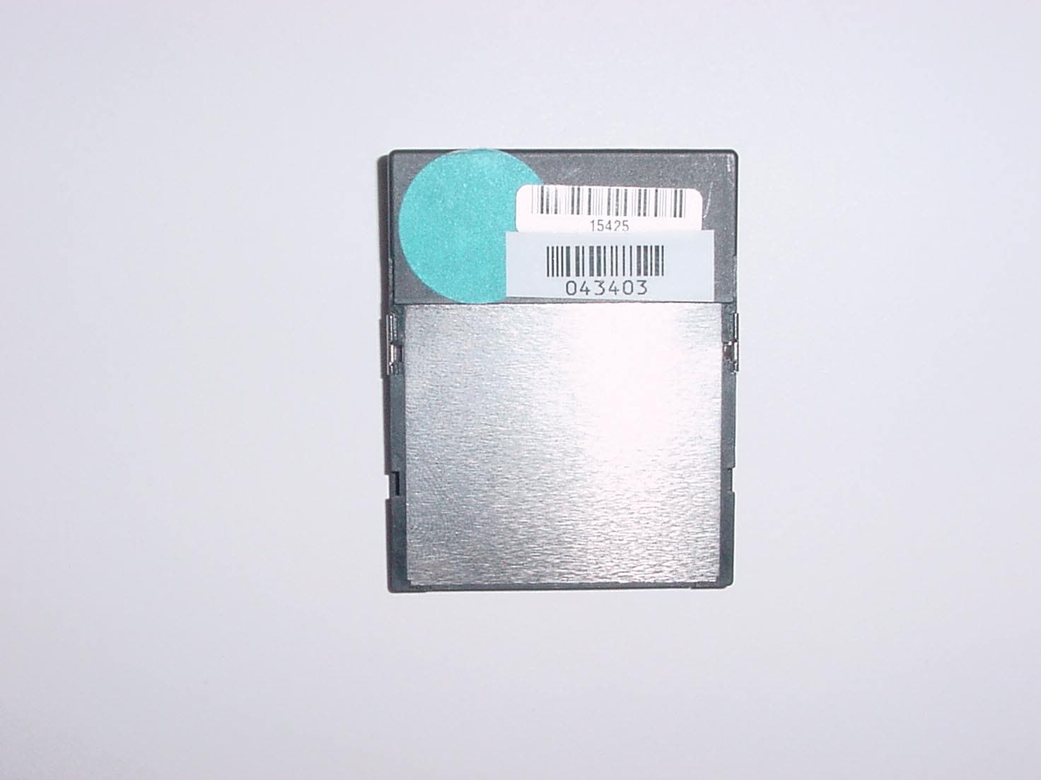
RIM-ICFR
Nov 20, 2003Compact Flash Radio
Equipment Class
DSS - Part 15 Spread Spectrum Transmitter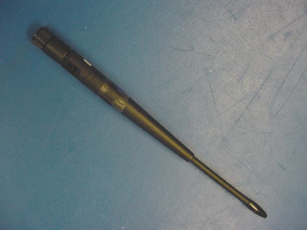
RIM-IMON
Oct 22, 2003Wireless Intelligent Monitors
Equipment Class
DSS - Part 15 Spread Spectrum Transmitter