RIM-ICFRCompact Flash Radio
FB iMonitoring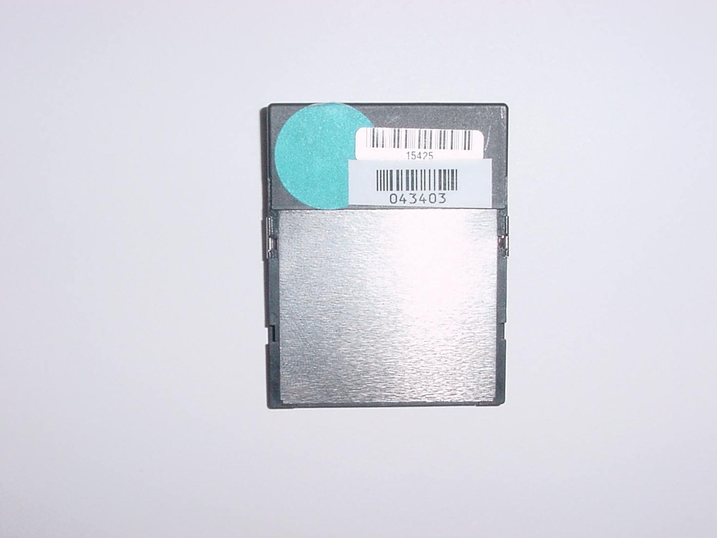
Click to zoom
Application Details
- Equipment Class
- DSS - Part 15 Spread Spectrum Transmitter
- Date of Grant
- Nov 20, 2003
- Application Purpose
- Original Equipment
- Date of Application
- Nov 20, 2003
- Equipment Note
- Compact Flash Radio
- Frequency Range
- 902.49140000 - 927.76950000
- Company
- FB iMonitoring
- Country
- United States
Documents & Files
Document Text
Text extracted from the exhibit documents filed with the FCC. Open a document above to read the original.
Cover Letter(s)
American Telecommunications Certification Body Inc. 6731 Whittier Ave, McLean, VA 22101 November 11, 2003 RE: Luna iMonitoring FCC ID: RIM-ICFR I have a few comments on the above referenced Application. 1) The label include the FCC logo, which is assumed to be for the PC peripheral portion of the device. Note that the label is missing the "FOR HOME OR OFFICE USE" and "TESTED TO COMPLY WITH FCC STANDARDS" as given in 15.19. According to 15.19(b)(3) this information may be contained in the manual, however it could not be found. Please explain where this information may be found in the users manual. 2) Note that a device subject to a DoC is also required to be accompanied by a compliance information sheet . The Statement of Compliance page must also include the information specified in item (2) given below. Note that all information required on the compliance sheet must be on a single page. This information was not found per 2.1077. Please provide. COMPLIANCE INFORMATION (47CFR 2.1077) If a product is tested and authorized under a Declaration of Conformity, a compliance information statement shall be supplied with the product at the time of marketing or importation, containing the following information on a single page: (1) Identification of the product, i.e. name and model number. (2) A statement similar to that contained in Section 15.19(a)(3) that the product complies with Part 15 of the regulations. (3) The identification, by name, address and telephone number, of the responsible party. The responsible party is defined as either the manufacturer, or if the equipment is imported, the importer. The responsible party for a Declaration of Conformity must be located within the United States. 3) RF exposure results appear to miscalculated. We show that for 4 mW, 0 dBi antenna, that the results should be 0.0008 mW/cm^2. Please verify. 4) Please confirm that the spur at the bandedge just above 928 MHz is > 26 dB below the fundamental. Certain interpretations could consider this a portion of the fundamental emission and not just a spurious emission if the delta is < 26 dB. 5) Please explain the derivation of limits 81.3, 84.4, and 82.0 given in tables 9-2 through 9-4. These do not appear to be based on the results of the fundamental - 20 dB from section 6 of the report 6) The levels in 6 of the report for the fundamental appears to be 6-7 dB higher than the power reported for this device. Please explain. 7) The results of 4639 MHz given in Table 9-4 do fall in a restricted band and are subject to the limits of 54 dBuV/m. Please correct. 8) There appears to be an error in the peak data for 2783.466 MHz in table 9-4. Please verify. 9) For purposes of Average measurements in section 9.3, please verify that the carrier was hop stopped and non- pulsing during these tests. If the device was not appropriately hop stopped with a non-pulsing carrier, then the use of the AVG detector using standard RBW = 1 MHz and VBW = 10 Hz may not be allowed. 10) Since the gain of the antenna is known, the preferred method for measuring output power would be to utilize the far field equation as specified in the public notice instead of the substitution method. Please see attached measurement guidance notes. 11) Please explain compliance of the EUT to 15.247(g)/(h) and 2.1033(b)(10). --- Continued on Next Page --- z Page 2November 11, 2003 12) Page 28 of the users manual shows a test mode that allows the device to be hop-stopped. The end user should not have access to such control of the device (15.15(b)). Please explain. Timothy R. Johnson Examining Engineer mailto: [email protected] The items indicated above must be submitted before processing can continue on the above referenced application. Failure to provide the requested information may result in application termination. Correspondence should be considered part of the permanent submission and may be viewed from the Internet after a Grant of Equipment Authorization is issued. Please do not respond to this correspondence using the email reply button. In order for your response to be processed expeditiously, you must submit your documents through the AmericanTCB.com website. Also, please note that partial responses increase processing time and should not be submitted. Any questions about the content of this correspondence should be directed to the sender.
Cover Letter(s)
American Telecommunications Certification Body Inc. 6731 Whittier Ave, McLean, VA 22101 November 14, 2003 RE: Luna iMonitoring FCC ID: RIM-ICFR I have a few comments on the above referenced Application. 1) The label include the FCC logo, which is assumed to be for the PC peripheral portion of the device. Note that the label is missing the "FOR HOME OR OFFICE USE" and "TESTED TO COMPLY WITH FCC STANDARDS" as given in 15.19. According to 15.19(b)(3) this information may be contained in the manual, however it could not be found. Please explain where this information may be found in the users manual. Response : The EUT is exclusively used in industrial environments, such as oil and gas fields. The Part 15.19 language mentioned above was not shown on the EUT or the user’s manual as this language would imply an operating environment that is not applicable. 2) Note that a device subject to a DoC is also required to be accompanied by a compliance information sheet . The Statement of Compliance page must also include the information specified in item (2) given below. Note that all information required on the compliance sheet must be on a single page. This information was not found per 2.1077. Please provide. COMPLIANCE INFORMATION (47CFR 2.1077) If a product is tested and authorized under a Declaration of Conformity, a compliance information statement shall be supplied with the product at the time of marketing or importation, containing the following information on a single page: (1) Identification of the product, i.e. name and model number. (2) A statement similar to that contained in Section 15.19(a)(3) that the product complies with Part 15 of the regulations. (3) The identification, by name, address and telephone number, of the responsible party. The responsible party is defined as either the manufacturer, or if the equipment is imported, the importer. The responsible party for a Declaration of Conformity must be located within the United States. Response : Please see the compliance information statement uploaded with this response. 3) RF exposure results appear to miscalculated. We show that for 4 mW, 0 dBi antenna, that the results should be 0.0008 mW/cm^2. Please verify. Response : The RF exposure calculation has been removed from the revised report. The EUT is excluded from SAR evaluation because of the low EIRP. Furthermore, the EUT power level is well below the 60/f(GHz) threshold on the TCB Exclusion List. 4) Please confirm that the spur at the bandedge just above 928 MHz is > 26 dB below the fundamental. Certain interpretations could consider this a portion of the fundamental emission and not just a spurious emission if the delta is < 26 dB. Response : The signal shown on the plot was ambient noise. Another plot has been taken with the appropriate reference level. Please see the revised report uploaded with this response. American Telecommunications Certification Body Inc. 6731 Whittier Ave, McLean, VA 22101 5) Please explain the derivation of limits 81.3, 84.4, and 82.0 given in tables 9-2 through 9-4. These do not appear to be based on the results of the fundamental - 20 dB from section 6 of the report. Response : The limit is based on 20 dB below the carrier. Since the unit has a bandwidth around 100 kHz, and the band edge plots are taken at 30 kHz, the level shown on the Band Edge would be lower. 6) The levels in 6 of the report for the fundamental appears to be 6-7 dB higher than the power reported for this device. Please explain. Response : Please see the revised report uploaded with this response. 7) The results of 4639 MHz given in Table 9-4 do fall in a restricted band and are subject to the limits of 54 dBuV/m. Please correct. Response : Please see the revised report uploaded with this response. 8) There appears to be an error in the peak data for 2783.466 MHz in table 9-4. Please verify. Response : Please see the revised report uploaded with this response. 9) For purposes of Average measurements in section 9.3, please verify that the carrier was hop stopped and non-pulsing during these tests. If the device was not appropriately hop stopped with a non-pulsing carrier, then the use of the AVG detector using standard RBW = 1 MHz and VBW = 10 Hz may not be allowed. Response : Hopping was disabled and the carrier was non-pulsing during these tests. 10) Since the gain of the antenna is known, the preferred method for measuring output power would be to utilize the far field equation as specified in the public notice instead of the substitution method. Please see attached measurement guidance notes. Response : Please see the revised report uploaded with this response. 11) Please explain compliance of the EUT to 15.247(g)/(h) and 2.1033(b)(10). Response : The frequencies shown in Table 1 of “2003153 Luna iMonitoring FCC & IC Test Report APX F FHSS.pdf” are the only frequencies used by the system. Additionally, the system receiver has an input bandwidth that matches the hopping channel bandwidths. This clarification has been added to the revised FHSS description (“2003153 Luna iMonitoring FCC & IC Test Report APX F FHSS.pdf”) uploaded with this response. 12) Page 28 of the users manual shows a test mode that allows the device to be hop-stopped. The end user should not have access to such control of the device (15.15(b)). Please explain. Response : The “Advanced Parameters Menu” and the “RF Test Menu” are no longer included in the “PocketConf” application software. Reference to these menus has been deleted from the Installer’s Manual. Please see the revised Installer’s Manual uploaded with this response. Timothy R. Johnson Examining Engineer mailto: [email protected] The items indicated above must be submitted before processing can continue on the above referenced application. Failure to provide the requested information may result in application termination. Correspondence should be considered part of the permanent submission and may be viewed from the Internet after a Grant o…
Text truncated - open the document above for the full version.
Cover Letter(s)
Rhein Tech Laboratories, Inc. Client: Luna iMonitoring 360 Herndon Parkway Model Name: iCFR Suite 1400 FCC ID: RIM-ICFR FCC: 15.247 Herndon, VA 20170 http://www.rheintech.com IC: RSS-210 Page 33 of 49 APPENDIX C: AGENCY AUTHORIZATION LETTER Please refer to the following page.
Cover Letter(s)
Rhein Tech Laboratories, Inc. Client: Luna iMonitoring 360 Herndon Parkway Model Name: iCFR Suite 1400 FCC ID: RIM-ICFR FCC: 15.247 Herndon, VA 20170 http://www.rheintech.com IC: RSS-210 Page 34 of 49 APPENDIX D: CONFIDENTIALITY REQUEST LETTER Please refer to the following page.
Cover Letter(s)
Rhein Tech Laboratories, Inc. Client: Luna iMonitoring 360 Herndon Parkway Model Name: iCFR Suite 1400 FCC ID: RIM-ICFR FCC: 15.247 Herndon, VA 20170 http://www.rheintech.com IC: RSS-210 Page 35 of 49 APPENDIX E: MANUFACTURER’S ATTESTATION Please refer to the following page for an attestation regarding the modifications.
External Photos
Rhein Tech Laboratories, Inc. Client: Luna iMonitoring 360 Herndon Parkway Model Name: iCFR Suite 1400 FCC ID: RIM-ICFR FCC: 15.247 Herndon, VA 20170 http://www.rheintech.com IC: RSS-210 Page 48 of 49 APPENDIX N: EXTERNAL PHOTOGRAPHS PHOTOGRAPH 7: iCFR FRONT Rhein Tech Laboratories, Inc. Client: Luna iMonitoring 360 Herndon Parkway Model Name: iCFR Suite 1400 FCC ID: RIM-ICFR FCC: 15.247 Herndon, VA 20170 http://www.rheintech.com IC: RSS-210 Page 49 of 49 PHOTOGRAPH 8: iCFR REAR
ID Label/Location Info
Rhein Tech Laboratories, Inc. Client: Luna iMonitoring 360 Herndon Parkway Model Name: iCFR Suite 1400 FCC ID: RIM-ICFR FCC: 15.247 Herndon, VA 20170 http://www.rheintech.com IC: RSS-210 Page 38 of 49 APPENDIX H: LABEL AND LABEL LOCATION Please see the following pages for a sample of the FCC and Industry Canada Identification Label, and label location. Model: SN: CFR11800000 1.5” x .6” i Monitoring RIM-ICFR FCC ID: 4747A-ICFR IC: iCFR FCC ID LABEL LOCATION ON REAR OF UNIT FCC ID LABEL HERE
Internal Photos
Rhein Tech Laboratories, Inc. Client: Luna iMonitoring 360 Herndon Parkway Model Name: iCFR Suite 1400 FCC ID: RIM-ICFR FCC: 15.247 Herndon, VA 20170 http://www.rheintech.com IC: RSS-210 Page 46 of 49 APPENDIX M: INTERNAL PHOTOGRAPHS PHOTOGRAPH 5: iCFR FRONT Rhein Tech Laboratories, Inc. Client: Luna iMonitoring 360 Herndon Parkway Model Name: iCFR Suite 1400 FCC ID: RIM-ICFR FCC: 15.247 Herndon, VA 20170 http://www.rheintech.com IC: RSS-210 Page 47 of 49 PHOTOGRAPH 6: iCFR REAR
Operational Description
Rhein Tech Laboratories, Inc. Client: Luna iMonitoring 360 Herndon Parkway Model Name: iCFR Suite 1400 FCC ID: RIM-ICFR FCC: 15.247 Herndon, VA 20170 http://www.rheintech.com IC: RSS-210 Page 32 of 49 APPENDIX B: ANTENNA SPECIFICATIONS PER FCC §15.204(C) The antenna is implemented on the PCB and has a gain of 0 dBi.
Test Report
Engineering and Testing for EMC and Safety Compliance 360 Herndon Parkway, Suite 1400 Herndon, VA 20170 Phone: 703-689-0368; Fax: 703-689-2056; Metro: 703-471-6441 CERTIFICATION APPLICATION REPORT FCC PART 15.247 & INDUSTRY CANADA RSS-210 Test Lab: Rhein Tech Laboratories, Inc. Phone: 703-689-0368 360 Herndon Parkway Fax: 703-689-2056 Suite 1400 Web Site: www.rheintech.com Herndon, VA 20170 E-Mail: [email protected] Applicant: Luna iMonitoring Phone: 540-558-1692 Contact: Roger Secrest Fax: 540-951-0760 2851 Commerce Street E-Mail: [email protected] Blacksburg, VA 24060 FCC ID RIM-ICFR GRANTEE FRN NUMBER 0009610718 PLAT FORM PDAs with a mini-PCI slot RTL WORK ORDER NUMBER 2003153 MODEL NUMBER / NAME iCFR RTL QUOTE NUMBER QRTL03-970 DATE OF TEST REPORT October 30, 2003 American National Standard Institute ANSI C63.4: Methods of Measurement of Radio-Noise Emissions from Low-Voltage Electrical and Electronic Equipment in the Range of 9 kHz to 40 GHz FCC Classification DSS – Part 15 Spread Spectrum Transmitter Frequency Hopping FCC Rule Part(s) Part 15.247: Operation within the bands 902-928 MHz, 2400-2483.5 MHz and 5725-5850 MHz Frequency Hopping System Industry Canada Standard RSS-210: Low Power License-Exempt Radio Communication Devices (All Frequency Bands) Digital Interface Information Digital Interface was found to be compliant Receiver Information Receiver was found to be compliant Frequency Range (MHz) Power output (W) Frequency Tolerance Emission Designator 902 – 928 0.007 N/A N/A We, the undersigned, hereby declare that the equipment tested and referenced in this report conforms to the identified standard(s) as described in this test report. Furthermore, there was no deviation from, additions to, or exclusions from the FCC Part 2, FCC Part 15, Industry Canada RSS-210, and ANSI C63.4 Signature: Date: October 30, 2003 Typed/Printed Name: Desmond A. Fraser Position: President Rhein Tech Laboratories, Inc. Client: Luna iMonitoring 360 Herndon Parkway Model Name: iCFR Suite 1400 FCC ID: RIM-ICFR FCC: 15.247 Herndon, VA 20170 http://www.rheintech.com IC: RSS-210 Page 2 of 49 TABLE OF CONTENTS 1 GENERAL INFORMATION........................................................................................................................................ 5 1.1 SCOPE .....................................................................................................................................................................................5 1.2 TEST FACILITY .....................................................................................................................................................................5 1.3 RELATED SUBMITTAL(S)/GRANT(S)................................................................................................................................5 1.4 MODIFICATIONS ..................................................................................................................................................................5 2 TEST INFORMATION................................................................................................................................................. 6 2.1 TEST JUSTIFICATION ..........................................................................................................................................................6 2.2 EXERCISING THE EUT .........................................................................................................................................................6 2.3 TEST RESULT SUMMARY ...................................................................................................................................................6 2.4 TEST SYSTEM DETAILS ......................................................................................................................................................7 2.5 CONFIGURATION OF TESTED SYSTEM ...........................................................................................................................8 3 COMPLIANCE WITH FCC §15.31(M) ....................................................................................................................... 9 4 COMPLIANCE WITH FCC §15.203 ........................................................................................................................... 9 5 COMPLIANCE WITH FCC §15.204 ........................................................................................................................... 9 6 COMPLIANCE WITH THE BAND EDGE – FCC §15.247(C), §15.205; IC RSS-210 §6.3 .................................... 10 6.1 TEST PROCEDURE..............................................................................................................................................................10 6.2 BAND EDGE TEST EQUIPMENT.......................................................................................................................................10 6.3 RESTRICTED BAND EDGE PLOTS ...................................................................................................................................11 7 CONDUCTED LIMITS - §15.207 .............................................................................................................................. 13 7.1 TEST METHODOLOGY FOR CONDUCTED LINE EMISSIONS MEASUREMENTS ...................................................13 7.2 CONDUCTED LINE EMISSION TEST ...............................................................................................................................13 7.3 CONDUCTED LINE TEST EQUIPMENT ...........................................................................................................................13 7.4 CONDUCTED LINE EMISSION TEST DATA ...................................................................................................................14 8 RADIATED EMISSION LIMITS RECEIVER/DIGITAL INTERFACE – FCC §15.209; IC RSS-210 §7.3.........…
Text truncated - open the document above for the full version.
Test Setup Photos
Rhein Tech Laboratories, Inc. Client: Luna iMonitoring 360 Herndon Parkway Model Name: iCFR Suite 1400 FCC ID: RIM-ICFR FCC: 15.247 Herndon, VA 20170 http://www.rheintech.com IC: RSS-210 Page 42 of 49 APPENDIX L: TEST PHOTOGRAPHS PHOTOGRAPH 1: iCFR FRONT – RADIATED TESTING Rhein Tech Laboratories, Inc. Client: Luna iMonitoring 360 Herndon Parkway Model Name: iCFR Suite 1400 FCC ID: RIM-ICFR FCC: 15.247 Herndon, VA 20170 http://www.rheintech.com IC: RSS-210 Page 43 of 49 PHOTOGRAPH 2: iCFR REAR – RADIATED TESTING Rhein Tech Laboratories, Inc. Client: Luna iMonitoring 360 Herndon Parkway Model Name: iCFR Suite 1400 FCC ID: RIM-ICFR FCC: 15.247 Herndon, VA 20170 http://www.rheintech.com IC: RSS-210 Page 44 of 49 PHOTOGRAPH 3: ICFR FRONT – CONDUCTED TESTING Rhein Tech Laboratories, Inc. Client: Luna iMonitoring 360 Herndon Parkway Model Name: iCFR Suite 1400 FCC ID: RIM-ICFR FCC: 15.247 Herndon, VA 20170 http://www.rheintech.com IC: RSS-210 Page 45 of 49 PHOTOGRAPH 4: iCFR REAR – CONDUCTED TESTING
Contact Information
Applicant
Roger A. Secrest(Systems Engineer)
Technical Contact
Rhein Tech LaboratoriesDesmond Fraser
[email protected]703-689-0368
360 Herndon Parkway · Herndon, Virginia · United States
Non-Technical Contact
Rhein Tech LaboratoriesKathy Grzovic
[email protected]703-689-0368
Test Firm
Rhein Tech Laboratories, Inc.Rick McMurray
Technical Specifications
| # | Rule Parts | Frequency Range | Power Output |
|---|---|---|---|
| 1 | 15C | 902.4914 MHz - 927.7695 MHz | 7.60 mW |
Other Applications from FB iMonitoring
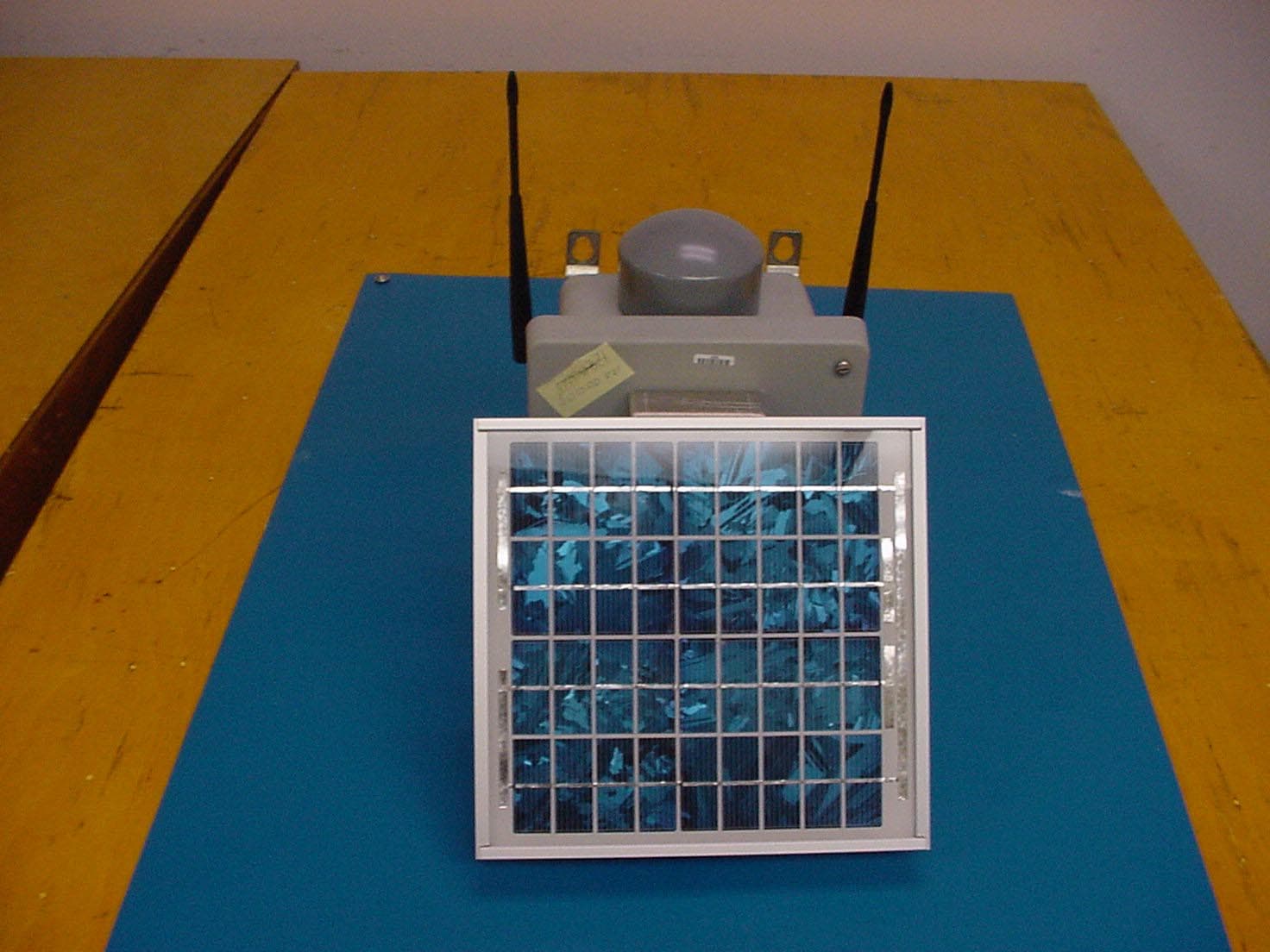
RIM-ICCU
Dec 16, 2003Concentration and Communications Unit
Equipment Class
DSS - Part 15 Spread Spectrum Transmitter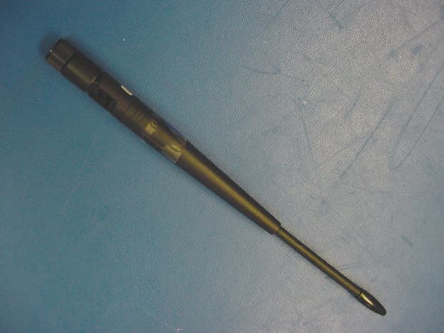
RIM-IMON
Oct 22, 2003Wireless Intelligent Monitors
Equipment Class
DSS - Part 15 Spread Spectrum Transmitter