RIM-IMONWireless Intelligent Monitors
FB iMonitoring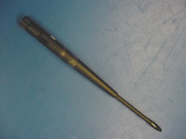
Click to zoom
Application Details
- Equipment Class
- DSS - Part 15 Spread Spectrum Transmitter
- Date of Grant
- Oct 22, 2003
- Application Purpose
- Original Equipment
- Date of Application
- Oct 22, 2003
- Equipment Note
- Wireless Intelligent Monitors
- Frequency Range
- 902.49000000 - 927.77000000
- Company
- FB iMonitoring
- Country
- United States
Documents & Files
Document Text
Text extracted from the exhibit documents filed with the FCC. Open a document above to read the original.
Users Manual
Rhein Tech Laboratories, Inc. Client: Luna iMonitoring 360 Herndon Parkway Model Name/#: iEFM, iTLM-1, iWPM-T Suite 1400 FCC ID: RIM-IMON FCC: 15.247 Herndon, VA 20170 http://www.rheintech.com IC: RSS-210 Page 86 of 86 APPENDIX N: PROFESSIONAL INSTALLATION Please refer to the following page.
Users Manual
Rhein Tech Laboratories, Inc. Client: Luna iMonitoring 360 Herndon Parkway Model Name/#: iEFM, iTLM-1, iWPM-T Suite 1400 FCC ID: RIM-IMON FCC: 15.247 Herndon, VA 20170 http://www.rheintech.com IC: RSS-210 Page 45 of 86 APPENDIX J: MANUAL Please refer to the following pages. Oil & Gas Wireless Enabled Monitoring System Installer’s Guide Oil & Gas Wireless Enabled Monitoring System Installer’s Guide Document version B.1 © 2003 Luna iMonitoring, Inc. 2903 Commerce Street, Suite A Blacksburg, VA 24060 Phone: 540.557.5880 Fax: 540.951.0760 E-mail: [email protected] Web: www.lunaimonitoring.com No portion of this publication may be reproduced or transmitted by any means without the written permission of Luna iMonitoring, Inc. 1 1 1 1 1 1 1 1 1 1 1 1 1 1 iii Contents 1Introduction The Intelligent Wireless Sensor Suite . . . . . . . . . . . . . . . . . . . . . . . . . . . . . . . . . . . . . . 2 WEMS Components . . . . . . . . . . . . . . . . . . . . . . . . . . . . . . . . . . . . . . . . . . . . . . . . . . . . . 2 Concentration and Communications Unit (iCCU) . . . . . . . . . . . . . . . . . . . . . . . . . . . . . . . 4 Compact Flash Radio (iCFR) . . . . . . . . . . . . . . . . . . . . . . . . . . . . . . . . . . . . . . . . . . . . . 4 Electronic Flow Monitor (iEFM) . . . . . . . . . . . . . . . . . . . . . . . . . . . . . . . . . . . . . . . . . . . 4 Tank Level Monitor (iTLM-1) . . . . . . . . . . . . . . . . . . . . . . . . . . . . . . . . . . . . . . . . . . . . . 5 Wellhead Pressure Monitor (iWPM-T) . . . . . . . . . . . . . . . . . . . . . . . . . . . . . . . . . . . . . . . 5 Secure Digital (SD) Card . . . . . . . . . . . . . . . . . . . . . . . . . . . . . . . . . . . . . . . . . . . . . . . . 6 User-supplied Components . . . . . . . . . . . . . . . . . . . . . . . . . . . . . . . . . . . . . . . . . . . . . . . 6 2Installation Site Selection for WEMS Components . . . . . . . . . . . . . . . . . . . . . . . . . . . . . . . . . . . . . . 7 Guidelines Concerning RF Signal Transmission . . . . . . . . . . . . . . . . . . . . . . . . . . . . . . . . 7 Guidelines Concerning Solar Panels . . . . . . . . . . . . . . . . . . . . . . . . . . . . . . . . . . . . . . . . 9 Guidelines Concerning Hazardous Environments . . . . . . . . . . . . . . . . . . . . . . . . . . . . . . . 9 Guidelines Concerning iTLM-1 Mounting . . . . . . . . . . . . . . . . . . . . . . . . . . . . . . . . . . . 10 Pre-installation iTLM-1 Depth Calibration . . . . . . . . . . . . . . . . . . . . . . . . . . . . . . . . . . 11 Installation Instructions . . . . . . . . . . . . . . . . . . . . . . . . . . . . . . . . . . . . . . . . . . . . . . . . 11 Monitor Installation Instructions . . . . . . . . . . . . . . . . . . . . . . . . . . . . . . . . . . . . . . . . . 11 iCCU Installation Instructions . . . . . . . . . . . . . . . . . . . . . . . . . . . . . . . . . . . . . . . . . . . 12 3 WEMS Software Installing the WEMS Software . . . . . . . . . . . . . . . . . . . . . . . . . . . . . . . . . . . . . . . . . . . 13 1 1 1 1 1 1 1 1 1 1 1 1 1 1 iv Contents Sensor Charge Modes . . . . . . . . . . . . . . . . . . . . . . . . . . . . . . . . . . . . . . . . . . . . . . . . 18 iCCU Uplink Menu . . . . . . . . . . . . . . . . . . . . . . . . . . . . . . . . . . . . . . . . . . . . . . . . 33 iEFM Sensor Calibration . . . . . . . . . . . . . . . . . . . . . . . . . . . . . . . . . . . . . . . . . . . . 36 iEFM Gas Calibration . . . . . . . . . . . . . . . . . . . . . . . . . . . . . . . . . . . . . . . . . . . . . . 37 iEFM Sensor Data . . . . . . . . . . . . . . . . . . . . . . . . . . . . . . . . . . . . . . . . . . . . . . . . 37 iTLM-1 Temperature Calibration . . . . . . . . . . . . . . . . . . . . . . . . . . . . . . . . . . . . . . 39 iWPM-T Pressure Sensor Calibration . . . . . . . . . . . . . . . . . . . . . . . . . . . . . . . . . . . 43 iWPM-T Temperature Calibration . . . . . . . . . . . . . . . . . . . . . . . . . . . . . . . . . . . . . . 44 Setting the Default ReSync Time . . . . . . . . . . . . . . . . . . . . . . . . . . . . . . . . . . . . . . . . 45 Exiting the Software . . . . . . . . . . . . . . . . . . . . . . . . . . . . . . . . . . . . . . . . . . . . . . . . . . . 53 A Specifications B Technical Support C Using the Charge Cable 1 1 1 1 1 1 1 1 1 1 1 1 1 1 1 Chapter 1 Introduction Figure 1-1. Applications for Luna iMonitoring’s Intelligent Wireless Sensor Suite The Luna iMonitoring Oil and Gas Wireless Enabled Monitoring System (WEMS) is a network of monitors and computers used to collect production data within an oil field environment. Sensor and communication modules collect and transmit data via wireless RF and satellite links. These modules are part of Luna iMonitoring’s Intelligent Wireless Sensor Suite. 1 1 1 1 1 1 1 1 1 1 1 1 1 1 2Chapter 1 Introduction The wireless oil field provides innovative, low-cost, remote asset management. Some of the advantages of wireless sensing include •reduce cost for field labor and transportation; •reduce administration cost for recording, generating, and distribut- ing reports; •provide better information to the Production Engineer for decision making; •provide more efficient tasking of the Pumper; •enhance revenue through optimized well performance and reduced downtime. The Intelligent Wireless Sensor Suite Luna iMonitoring’s Intelligent Wireless Sensor Suite includes sensors, computers, software, and communication devices to collect and transmit data in a variety of industries and applications. The iMonitoring “smart” sensors use local processing to minimize power consumption and communication bandwidth. Intelligent software collects, processes, and stores the data in an information database. The iMonitoring system uses RF, cellular, Internet, and satellite links to transmit data between sensors, data collection sites, and central computers. For more information on the Intelligent Wireless Sensor Suite and its components, please visit the Luna iMonitori…
Text truncated - open the document above for the full version.
Users Manual
Rhein Tech Laboratories, Inc. Client: Luna iMonitoring 360 Herndon Parkway Model Name/#: iEFM, iTLM-1, iWPM-T Suite 1400 FCC ID: RIM-IMON FCC: 15.247 Herndon, VA 20170 http://www.rheintech.com IC: RSS-210 Page 86 of 86 APPENDIX N: PROFESSIONAL INSTALLATION Please refer to the following page.
Users Manual
Rhein Tech Laboratories, Inc. Client: Luna iMonitoring 360 Herndon Parkway Model Name/#: iEFM, iTLM-1, iWPM-T Suite 1400 FCC ID: RIM-IMON FCC: 15.247 Herndon, VA 20170 http://www.rheintech.com IC: RSS-210 Page 45 of 86 APPENDIX J: MANUAL Please refer to the following pages. Oil & Gas Wireless Enabled Monitoring System Installer’s Guide Oil & Gas Wireless Enabled Monitoring System Installer’s Guide Document version B.1 © 2003 Luna iMonitoring, Inc. 2903 Commerce Street, Suite A Blacksburg, VA 24060 Phone: 540.557.5880 Fax: 540.951.0760 E-mail: [email protected] Web: www.lunaimonitoring.com No portion of this publication may be reproduced or transmitted by any means without the written permission of Luna iMonitoring, Inc. 1 1 1 1 1 1 1 1 1 1 1 1 1 1 iii Contents 1Introduction The Intelligent Wireless Sensor Suite . . . . . . . . . . . . . . . . . . . . . . . . . . . . . . . . . . . . . . 2 WEMS Components . . . . . . . . . . . . . . . . . . . . . . . . . . . . . . . . . . . . . . . . . . . . . . . . . . . . . 2 Concentration and Communications Unit (iCCU) . . . . . . . . . . . . . . . . . . . . . . . . . . . . . . . 4 Compact Flash Radio (iCFR) . . . . . . . . . . . . . . . . . . . . . . . . . . . . . . . . . . . . . . . . . . . . . 4 Electronic Flow Monitor (iEFM) . . . . . . . . . . . . . . . . . . . . . . . . . . . . . . . . . . . . . . . . . . . 4 Tank Level Monitor (iTLM-1) . . . . . . . . . . . . . . . . . . . . . . . . . . . . . . . . . . . . . . . . . . . . . 5 Wellhead Pressure Monitor (iWPM-T) . . . . . . . . . . . . . . . . . . . . . . . . . . . . . . . . . . . . . . . 5 Secure Digital (SD) Card . . . . . . . . . . . . . . . . . . . . . . . . . . . . . . . . . . . . . . . . . . . . . . . . 6 User-supplied Components . . . . . . . . . . . . . . . . . . . . . . . . . . . . . . . . . . . . . . . . . . . . . . . 6 2Installation Site Selection for WEMS Components . . . . . . . . . . . . . . . . . . . . . . . . . . . . . . . . . . . . . . 7 Guidelines Concerning RF Signal Transmission . . . . . . . . . . . . . . . . . . . . . . . . . . . . . . . . 7 Guidelines Concerning Solar Panels . . . . . . . . . . . . . . . . . . . . . . . . . . . . . . . . . . . . . . . . 9 Guidelines Concerning Hazardous Environments . . . . . . . . . . . . . . . . . . . . . . . . . . . . . . . 9 Guidelines Concerning iTLM-1 Mounting . . . . . . . . . . . . . . . . . . . . . . . . . . . . . . . . . . . 10 Pre-installation iTLM-1 Depth Calibration . . . . . . . . . . . . . . . . . . . . . . . . . . . . . . . . . . 11 Installation Instructions . . . . . . . . . . . . . . . . . . . . . . . . . . . . . . . . . . . . . . . . . . . . . . . . 11 Monitor Installation Instructions . . . . . . . . . . . . . . . . . . . . . . . . . . . . . . . . . . . . . . . . . 11 iCCU Installation Instructions . . . . . . . . . . . . . . . . . . . . . . . . . . . . . . . . . . . . . . . . . . . 12 3 WEMS Software Installing the WEMS Software . . . . . . . . . . . . . . . . . . . . . . . . . . . . . . . . . . . . . . . . . . . 13 1 1 1 1 1 1 1 1 1 1 1 1 1 1 iv Contents Sensor Charge Modes . . . . . . . . . . . . . . . . . . . . . . . . . . . . . . . . . . . . . . . . . . . . . . . . 18 iCCU Uplink Menu . . . . . . . . . . . . . . . . . . . . . . . . . . . . . . . . . . . . . . . . . . . . . . . . 33 iEFM Sensor Calibration . . . . . . . . . . . . . . . . . . . . . . . . . . . . . . . . . . . . . . . . . . . . 36 iEFM Gas Calibration . . . . . . . . . . . . . . . . . . . . . . . . . . . . . . . . . . . . . . . . . . . . . . 37 iEFM Sensor Data . . . . . . . . . . . . . . . . . . . . . . . . . . . . . . . . . . . . . . . . . . . . . . . . 37 iTLM-1 Temperature Calibration . . . . . . . . . . . . . . . . . . . . . . . . . . . . . . . . . . . . . . 39 iWPM-T Pressure Sensor Calibration . . . . . . . . . . . . . . . . . . . . . . . . . . . . . . . . . . . 43 iWPM-T Temperature Calibration . . . . . . . . . . . . . . . . . . . . . . . . . . . . . . . . . . . . . . 44 Setting the Default ReSync Time . . . . . . . . . . . . . . . . . . . . . . . . . . . . . . . . . . . . . . . . 45 Exiting the Software . . . . . . . . . . . . . . . . . . . . . . . . . . . . . . . . . . . . . . . . . . . . . . . . . . . 53 A Specifications B Technical Support C Using the Charge Cable 1 1 1 1 1 1 1 1 1 1 1 1 1 1 1 Chapter 1 Introduction Figure 1-1. Applications for Luna iMonitoring’s Intelligent Wireless Sensor Suite The Luna iMonitoring Oil and Gas Wireless Enabled Monitoring System (WEMS) is a network of monitors and computers used to collect production data within an oil field environment. Sensor and communication modules collect and transmit data via wireless RF and satellite links. These modules are part of Luna iMonitoring’s Intelligent Wireless Sensor Suite. 1 1 1 1 1 1 1 1 1 1 1 1 1 1 2Chapter 1 Introduction The wireless oil field provides innovative, low-cost, remote asset management. Some of the advantages of wireless sensing include •reduce cost for field labor and transportation; •reduce administration cost for recording, generating, and distribut- ing reports; •provide better information to the Production Engineer for decision making; •provide more efficient tasking of the Pumper; •enhance revenue through optimized well performance and reduced downtime. The Intelligent Wireless Sensor Suite Luna iMonitoring’s Intelligent Wireless Sensor Suite includes sensors, computers, software, and communication devices to collect and transmit data in a variety of industries and applications. The iMonitoring “smart” sensors use local processing to minimize power consumption and communication bandwidth. Intelligent software collects, processes, and stores the data in an information database. The iMonitoring system uses RF, cellular, Internet, and satellite links to transmit data between sensors, data collection sites, and central computers. For more information on the Intelligent Wireless Sensor Suite and its components, please visit the Luna iMonitori…
Text truncated - open the document above for the full version.
Cover Letter(s)
Rhein Tech Laboratories, Inc. Client: Luna iMonitoring 360 Herndon Parkway Model Name/#: iEFM, iTLM-1, iWPM-T Suite 1400 FCC ID: RIM-IMON FCC: 15.247 Herndon, VA 20170 http://www.rheintech.com IC: RSS-210 Page 39 of 86 APPENDIX D: CONFIDENTIALITY REQUEST LETTER Please refer to the following page.
Cover Letter(s)
Rhein Tech Laboratories, Inc. Client: Luna iMonitoring 360 Herndon Parkway Model Name/#: iEFM, iTLM-1, iWPM-T Suite 1400 FCC ID: RIM-IMON FCC: 15.247 Herndon, VA 20170 http://www.rheintech.com IC: RSS-210 Page 38 of 86 APPENDIX C: AGENCY AUTHORIZATION LETTER Please refer to the following page.
Cover Letter(s)
Engineering and Testing for EMC and Safety Compliance Test Approach Justification The RF circuitry and antenna tested in this report are utilized in three Luna iMonitoring products: the iEFM, iTLM-1, iWPM-T. Though portions of the digital circuitry of the three products is different, the RF circuitry (including control circuitry) and layout is identical across the three products. But, because the RF circuitry and digital circuitry reside on the same PCB in each device, a modular approval approach would not be applicable. The conducted power of the three products was investigated on three frequencies each to see if any aspect of the digital circuitry influenced the intentional emissions. No significant power variation was found. The iTLM-1 was chosen for the remaining testing because of the present of the ultrasonic transducer, and the physical length of the transducer housing. The digital portions of the iEFM, iTLM-1, iWPM-T are subject to verification under FCC Part 15. Additionally, the iTLM-1 has an ultrasonic section that meets the definition of 18.107(f) and is subject to verification under FCC Part 18 as a non-consumer ISM device. Verification testing was performed on all three devices, and verification reports exist for each. Two antennas were tested and can be used with the devices: (Nearson S467AH-915S whip antenna and Bluewave EDY9432 Yagi). A reduced power setting must be used with the Bluewave EDY9432 Yagi for compliance. The manufacturer will pre-program the appropriate maximum power before shipment and insure that end users cannot use the Yagi antenna with a device programmed for use with the whip antenna. Sincerely, Richard B. McMurray, P.E.
Cover Letter(s)
American Telecommunications Certification Body Inc. 6731 Whittier Ave, McLean, VA 22101 October 14, 2003 RE: FCC ID: RIM-IMON_ATCB000839 Attention: Rick McMurray / Kathy Grzovic I have a few comments on this Application. 1. The 731 states the device operates under Part 15, 18 and 25. Please explain. 2. Please note that in accordance with 2.1033, block diagrams must contain the frequencies of all clocks and their paths. Please note that the block diagram provided does not contain this information. 3. Please note that while part 18 and part 25 may have their own particular statements to be included in the manual, the 2-condition statement is a part 15 only statement. Reference to these two conditions therefore should only reflect part 15. 4. While you have provided a letter from the manufacturer that the device will be professionally installed, this information needs to be contained in the user manual and a sample of the installation instructions need to be provided. These installation instructions must also clearly indicate that when using a YAGI antenna the power must be appropriately reduced. Please provide the installation instructions for this device. 5. Please note that in the photo “iTLM-1 RF SECTION BOTTOM” there appears to be another rf connector. This connector is not on the other models. Please explain this connector. 6. The description of the hop sequencing for the device is unclear. It appears from the description that all transmitters may be hopping in step with each other. It appears that the device transmits the hop sequence after 53 hops, thus repeating the same pattern. Also, it appears that the modulation of the hop frequency is off most or at least a large part of the time, however, the device apparently continues hopping. This would seem to violate the condition whereby a FHSS device starts at the next hop channel in the table for the next transmission. It may even appear as if the device even continues transmitting the hop channels without modulation. Please note that the definition of a FHSS system is “A spread spectrum system in which the carrier is modulated with the coded information in a conventional manner causing a conventional spreading of the RF energy about the frequency carrier. “ If the carrier is not modulated, it cannot spread the rf energy and thus is not a “spread Spectrum” device. Please clarify and explain the pseudorandom hopping of this system. 7. Please note that a modification appears to have been made to the device to make it comply. Please provide a letter from the manufacturer that this modification will be installed in all devices. Also, please provide revised schematics showing the inclusion of the modifications performed on the device. 8. Please note that the operational description says that The Microprocessor, radio, RF AMP, RF Switch, JTAG, RTC, LDO and Analog front end to the analog interfaces are all the same circuits and components. Please also note that the justification letter states the circuitry in the rf is ‘identical’. However, because the digital circuitry is different in all three devices and because this additional circuitry may cause significant variations in at least the radiated emissions of each individual device, it is not possible to determine the worse case emissions by arbitrary selection as stated in the report. Please provide evidence that the device used in testing produced the worse case emissions. 9. Please note that for the dwell time you have only shown that in a 1 sec sweep the dwell is only 390ms. However, the limit is 400ms within a 20 second time frame. Please explain how this shows compliance. Please note that from the explanation of the FHSS hopping description you have a condition where the 333ms dwell rate may exceed the 400ms over 20 seconds. (53 channels each dwelling at 333ms = 17.69seconds. This means that in the next hop sequence it may be possible for the 333ms dwell to exceed channel occupancy limits. This would be an analyzer setting of 20 seconds showing the number of 333ms pulses occurring. This would mean that only one 333mx transmission would be allowed during that 20 seconds on any one channel). z Page 2 October 14, 2003 Please explain and show that under the long dwell condition the device is compliant during the full 20 seconds time limit 10. FYI - Your documentation states that with the Yagi antenna a reduction in power is required. Please note that the Yagi antenna listed has a gain of 8.65dBi. The device has a conducted power output of 17.7dBm (59mW). The limit for a FHSS device in the 902 to 928MHz range using more than 50 hopping channels (your device is said to use 53) is 1 Watt (30dBm). This means with a 6dB gain antenna the device could output an EIRP of 36dBm. Reduction would then have to occur. With the conducted power listed this means that an antenna with a gain of almost 18dBi could be used before an equivalent reduction would have to occur. Unless the reason for reducing the power for the Yagi is for radiated emissions compliance, by not reducing the conducted power of this device, the range using the Yagi could be significantly increased. Dennis Ward mailto:[email protected] The items indicated above must be submitted before processing can continue on the above referenced application. Failure to provide the requested information may result in application termination. Correspondence should be considered part of the permanent submission and may be viewed from the Internet after a Grant of Equipment Authorization is issued. Please do not respond to this correspondence using the email reply button. In order for your response to be processed expeditiously, you must submit your documents through the AmericanTCB.com website. Also, please note that partial responses increase processing time and should not be submitted. Any questions about the content of this correspondence should be directed to the sender.
Cover Letter(s)
American Telecommunications Certification Body Inc. 6731 Whittier Ave, McLean, VA 22101 October 21, 2003 RE: FCC ID: RIM-IMON_ATCB000839 Attention: Rick McMurray / Kathy Grzovic I have a few comments on this Application. 1. The 731 states the device operates under Part 15, 18 and 25. Please explain. Response: The aspects of the device subject to certification fall under Part 15 only. Part 18 and 25 were incorrectly included on the 731 form. A revised 731 form is uploaded with this response. 2. Please note that in accordance with 2.1033, block diagrams must contain the frequencies of all clocks and their paths. Please note that the block diagram provided does not contain this information. Response: Please refer to the revised block diagram uploaded with this response. 3. Please note that while part 18 and part 25 may have their own particular statements to be included in the manual, the 2-condition statement is a part 15 only statement. Reference to these two conditions therefore should only reflect part 15. Response: Please refer to the manual uploaded with this response. 4. While you have provided a letter from the manufacturer that the device will be professionally installed, this information needs to be contained in the user manual and a sample of the installation instructions need to be provided. These installation instructions must also clearly indicate that when using a YAGI antenna the power must be appropriately reduced. Please provide the installation instructions for this device. Response: Please refer to the installation manual uploaded with this response. The reference to the YAGI antenna power issue is on page 12 of the manual. The units will be installed by personnel trained by Luna iMonitoring. The professional installer will utilize the installation manual and the necessary PDA software to install and provision the units. The user does not have access to the installation software, and none of the actions described in the installation manual are available to the user. 5. Please note that in the photo “iTLM-1 RF SECTION BOTTOM” there appears to be another rf connector. This connector is not on the other models. Please explain this connector. Response: The iTLM-1 contains an ultrasonic transducer that meets the definition of 18.107(f) and is subject to verification under Part 18 as a non-consumer ISM device. The connector in question connects to the ultrasonic transducer. A verification report exists for this aspect of the device. American Telecommunications Certification Body Inc. 6731 Whittier Ave, McLean, VA 22101 6. The description of the hop sequencing for the device is unclear. It appears from the description that all transmitters may be hopping in step with each other. It appears that the device transmits the hop sequence after 53 hops, thus repeating the same pattern. Also, it appears that the modulation of the hop frequency is off most or at least a large part of the time, however, the device apparently continues hopping. This would seem to violate the condition whereby a FHSS device starts at the next hop channel in the table for the next transmission. It may even appear as if the device even continues transmitting the hop channels without modulation. Please note that the definition of a FHSS system is “A spread spectrum system in which the carrier is modulated with the coded information in a conventional manner causing a conventional spreading of the RF energy about the frequency carrier. “ If the carrier is not modulated, it cannot spread the rf energy and thus is not a “spread Spectrum” device. Please clarify and explain the pseudorandom hopping of this system. Response: Please refer to the explanation uploaded with this response. 7. Please note that a modification appears to have been made to the device to make it comply. Please provide a letter from the manufacturer that this modification will be installed in all devices. Also, please provide revised schematics showing the inclusion of the modifications performed on the device. Response: Please refer to the cover letter exhibit and revised schematics, with notes, uploaded with this response. 8. Please note that the operational description says that The Microprocessor, radio, RF AMP, RF Switch, JTAG, RTC, LDO and Analog front end to the analog interfaces are all the same circuits and components. Please also note that the justification letter states the circuitry in the rf is ‘identical’. However, because the digital circuitry is different in all three devices and because this additional circuitry may cause significant variations in at least the radiated emissions of each individual device, it is not possible to determine the worse case emissions by arbitrary selection as stated in the report. Please provide evidence that the device used in testing produced the worse case emissions. Response: Based on an engineering investigation of the iEFM, iTLM-1, and iWPM-T schematics, PCB layout and mechanical assembly, we confirmed the manufacturer’s attestation that the RF portions of each device were identical. As further justification, the conducted output power of each device was tested on three channels to see if any single device had a significantly higher output power. No device had a significant difference in output power. The motivation for this investigation was the theory that if one of the devices had a significant power difference, this difference would also appear in the harmonic and spurious radiation, therefore requiring further investigation of that device or devices. Since no significant variation was found, other characteristics were investigated to see if they would have an effect on emissions. We determined that the iTLM-1 would represent a worst case device because of the presence of the ultrasonic transducer, and the physical length of the transducer housing. Additionally, the emissions from the digital portions all three devices were tested and found to be compliant with significant margins. Individ…
Text truncated - open the document above for the full version.
External Photos
Rhein Tech Laboratories, Inc. Client: Luna iMonitoring 360 Herndon Parkway Model Name/#: iEFM, iTLM-1, iWPM-T Suite 1400 FCC ID: RIM-IMON FCC: 15.247 Herndon, VA 20170 http://www.rheintech.com IC: RSS-210 Page 54 of 86 APPENDIX L: EXTERNAL PHOTOGRAPHS PHOTOGRAPH 9: ANTENNA PORT Rhein Tech Laboratories, Inc. Client: Luna iMonitoring 360 Herndon Parkway Model Name/#: iEFM, iTLM-1, iWPM-T Suite 1400 FCC ID: RIM-IMON FCC: 15.247 Herndon, VA 20170 http://www.rheintech.com IC: RSS-210 Page 55 of 86 PHOTOGRAPH 10: WHIP ANTENNA Rhein Tech Laboratories, Inc. Client: Luna iMonitoring 360 Herndon Parkway Model Name/#: iEFM, iTLM-1, iWPM-T Suite 1400 FCC ID: RIM-IMON FCC: 15.247 Herndon, VA 20170 http://www.rheintech.com IC: RSS-210 Page 56 of 86 PHOTOGRAPH 11: YAGI ANTENNA Rhein Tech Laboratories, Inc. Client: Luna iMonitoring 360 Herndon Parkway Model Name/#: iEFM, iTLM-1, iWPM-T Suite 1400 FCC ID: RIM-IMON FCC: 15.247 Herndon, VA 20170 http://www.rheintech.com IC: RSS-210 Page 57 of 86 PHOTOGRAPH 12: iEFM SIDE Rhein Tech Laboratories, Inc. Client: Luna iMonitoring 360 Herndon Parkway Model Name/#: iEFM, iTLM-1, iWPM-T Suite 1400 FCC ID: RIM-IMON FCC: 15.247 Herndon, VA 20170 http://www.rheintech.com IC: RSS-210 Page 58 of 86 PHOTOGRAPH 13: iEFM SIDE Rhein Tech Laboratories, Inc. Client: Luna iMonitoring 360 Herndon Parkway Model Name/#: iEFM, iTLM-1, iWPM-T Suite 1400 FCC ID: RIM-IMON FCC: 15.247 Herndon, VA 20170 http://www.rheintech.com IC: RSS-210 Page 59 of 86 PHOTOGRAPH 14: iEFM SIDE Rhein Tech Laboratories, Inc. Client: Luna iMonitoring 360 Herndon Parkway Model Name/#: iEFM, iTLM-1, iWPM-T Suite 1400 FCC ID: RIM-IMON FCC: 15.247 Herndon, VA 20170 http://www.rheintech.com IC: RSS-210 Page 60 of 86 PHOTOGRAPH 15: iEFM SIDE Rhein Tech Laboratories, Inc. Client: Luna iMonitoring 360 Herndon Parkway Model Name/#: iEFM, iTLM-1, iWPM-T Suite 1400 FCC ID: RIM-IMON FCC: 15.247 Herndon, VA 20170 http://www.rheintech.com IC: RSS-210 Page 61 of 86 PHOTOGRAPH 16: iEFM SIDE Rhein Tech Laboratories, Inc. Client: Luna iMonitoring 360 Herndon Parkway Model Name/#: iEFM, iTLM-1, iWPM-T Suite 1400 FCC ID: RIM-IMON FCC: 15.247 Herndon, VA 20170 http://www.rheintech.com IC: RSS-210 Page 62 of 86 PHOTOGRAPH 17: iTLM-1 BOTTOM Rhein Tech Laboratories, Inc. Client: Luna iMonitoring 360 Herndon Parkway Model Name/#: iEFM, iTLM-1, iWPM-T Suite 1400 FCC ID: RIM-IMON FCC: 15.247 Herndon, VA 20170 http://www.rheintech.com IC: RSS-210 Page 63 of 86 PHOTOGRAPH 18: iTLM-1 SIDE Rhein Tech Laboratories, Inc. Client: Luna iMonitoring 360 Herndon Parkway Model Name/#: iEFM, iTLM-1, iWPM-T Suite 1400 FCC ID: RIM-IMON FCC: 15.247 Herndon, VA 20170 http://www.rheintech.com IC: RSS-210 Page 64 of 86 PHOTOGRAPH 19: iTLM-1 SIDE Rhein Tech Laboratories, Inc. Client: Luna iMonitoring 360 Herndon Parkway Model Name/#: iEFM, iTLM-1, iWPM-T Suite 1400 FCC ID: RIM-IMON FCC: 15.247 Herndon, VA 20170 http://www.rheintech.com IC: RSS-210 Page 65 of 86 PHOTOGRAPH 20: iTLM-1 SIDE Rhein Tech Laboratories, Inc. Client: Luna iMonitoring 360 Herndon Parkway Model Name/#: iEFM, iTLM-1, iWPM-T Suite 1400 FCC ID: RIM-IMON FCC: 15.247 Herndon, VA 20170 http://www.rheintech.com IC: RSS-210 Page 66 of 86 PHOTOGRAPH 21: i…
Text truncated - open the document above for the full version.
Contact Information
Applicant
Roger A. Secrest(Systems Engineer)
Technical Contact
Rhein Tech LaboratoriesRick McMurray
[email protected]703-689-0368
360 Herndon Parkway, Suite 1400 · Herndon, Virginia · United States
Test Firm
Rhein Tech Laboratories, Inc.Rick McMurray
Technical Specifications
| # | Rule Parts | Frequency Range | Power Output |
|---|---|---|---|
| 1 | 15C | 902.49 MHz - 927.77 MHz | 59.00 mW |
Other Applications from FB iMonitoring
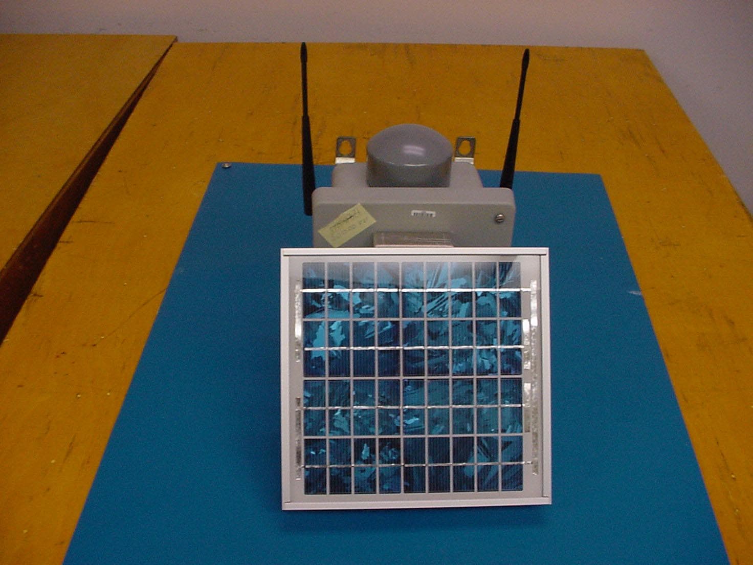
RIM-ICCU
Dec 16, 2003Concentration and Communications Unit
Equipment Class
DSS - Part 15 Spread Spectrum Transmitter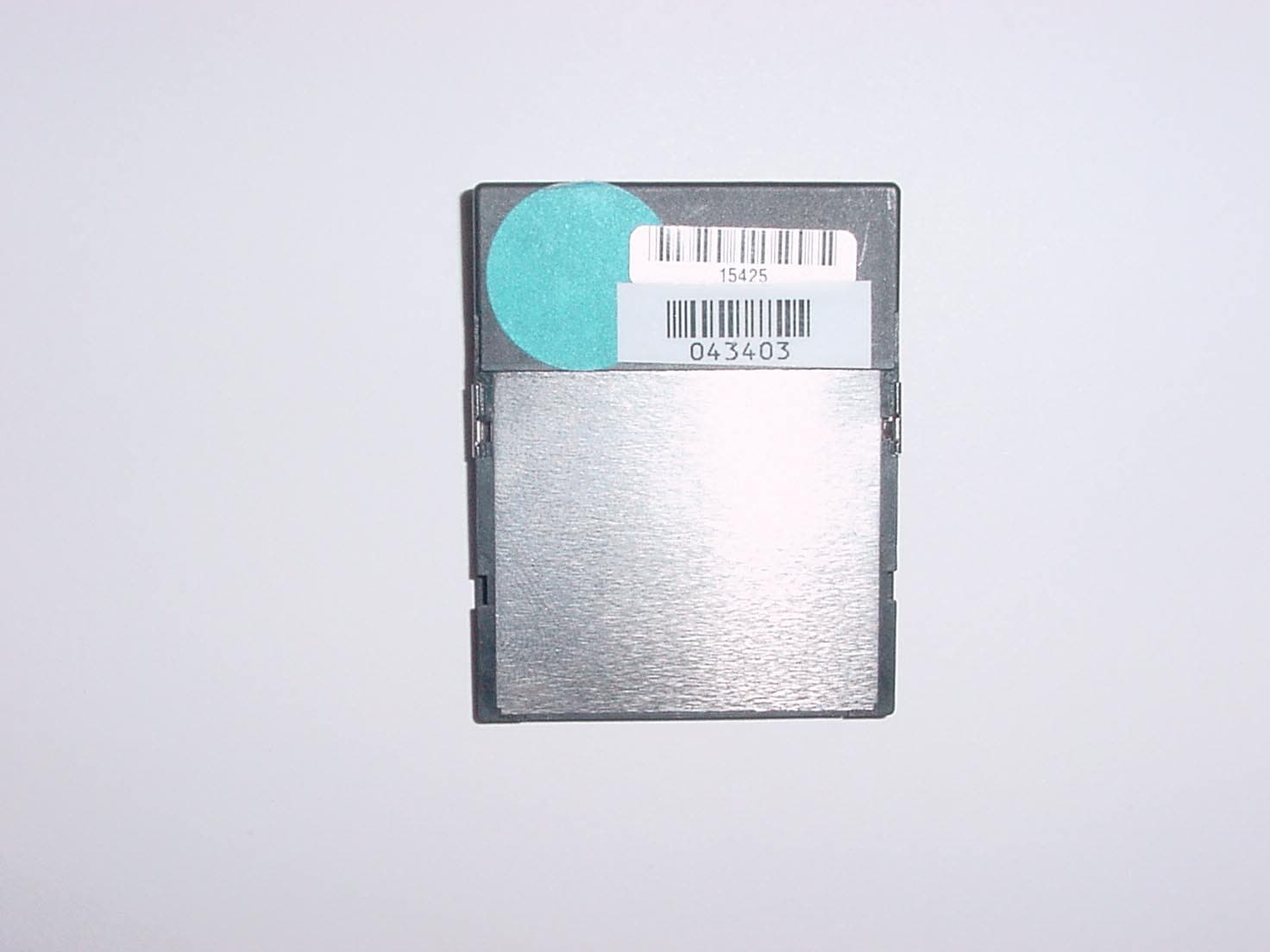
RIM-ICFR
Nov 20, 2003Compact Flash Radio
Equipment Class
DSS - Part 15 Spread Spectrum Transmitter