RIR-24ZT100Remote Controller
ZODIAC POOL SYSTEMS LLC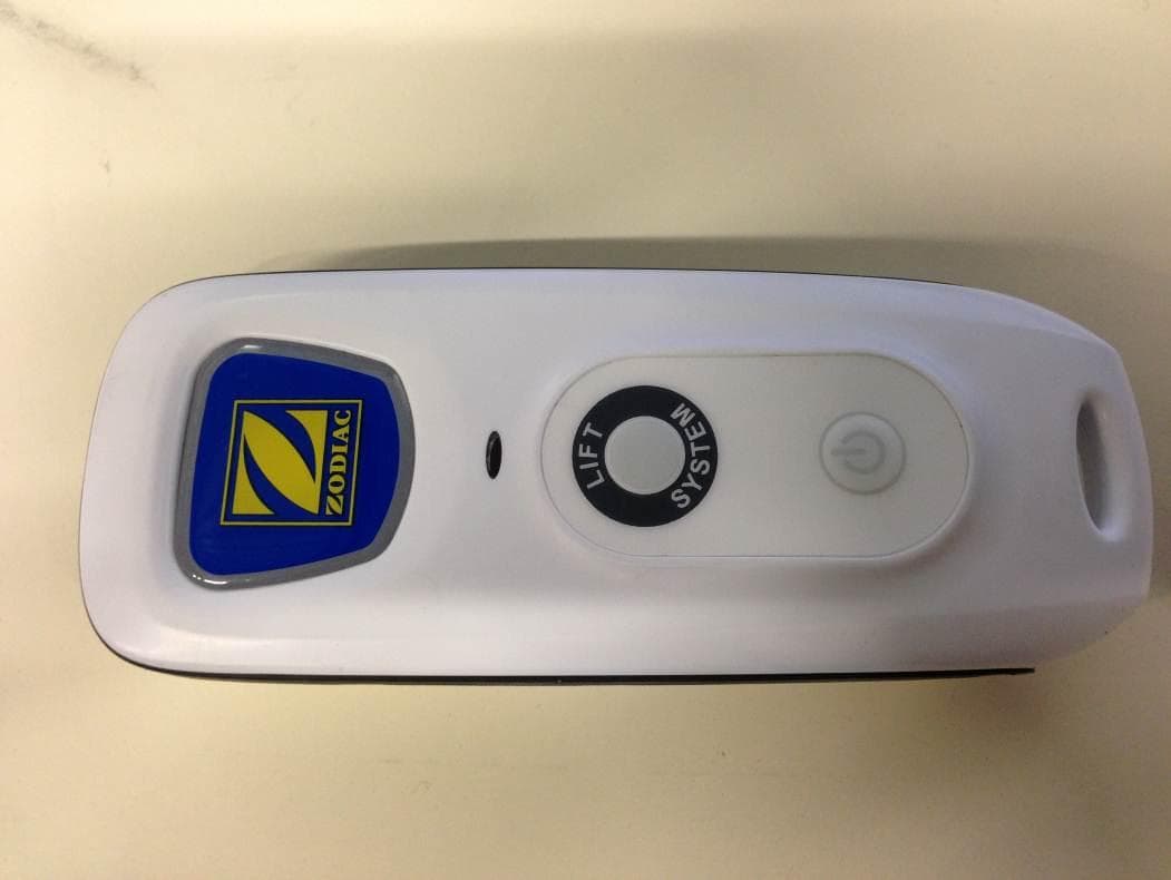
Click to zoom
Application Details
- Equipment Class
- DTS - Digital Transmission System
- Date of Grant
- Aug 01, 2013
- Application Purpose
- Original Equipment
- Date of Application
- Aug 01, 2013
- Equipment Note
- Remote Controller
- Frequency Range
- 2405.00000000 - 2480.00000000
- Company
- ZODIAC POOL SYSTEMS LLC
- Country
- United States
Documents & Files
Document Text
Text extracted from the exhibit documents filed with the FCC. Open a document above to read the original.
Users Manual
9400 OWNER’S MANUAL ENgLiSh | FRANçAiS | ESPAÑOL AVERTiSSEMENT POUR VOTRE SÉCURiTÉ – Pour toute opération autre que l’entretien de routine et la maintenance décrite dans ce manuel, ce produit doit être pris en charge par une entreprise qui est autorisée et qualifiée pour la réparation des équipements de piscine par la juridiction où le dit produit est installé lorsque de telles exigences locales ou provinciales sont édictées. Si aucune exigence locale ou provinciale n’est disponible, l’agent d’entretien doit être un professionnel avec suffisamment d’expérience dans l’installation et la maintenance d’équipement de piscine pour appliquer correctement les consignes du présent manuel. L’installation ou l’utilisation inappropriée annulera la garantie. WARNiNg FOR YOUR SAFETY - For anything other than the routine cleaning and maintenance described in this manual, this product must be serviced by a contractor who is licensed and qualified in pool equipment by the jurisdiction in which the product will be installed where such state or local requirements exist. in the event no such state or local requirement exists, the maintainer must be a professional with sufficient experience in pool equipment installation and maintenance so that all of the instructions in this manual can be followed exactly. improper installation and/or operation will void the warranty. H0392900 Rev B 9300/9400/9500 Sport P93/P94/P95 ADVERTENCiA PARA SU SEgURiDAD – Este producto debe ser instalado y mantenido por un contratista que está autorizado y calificado en equipo de piscina en las jurisdicción en la que el producto se instala donde existan requisitos estatales o locales. En el caso de ningún estado o locales obligatorio, el responsable debe ser un profesional con experiencia suficiente en la piscina de la instalación y mantenimiento de equipo para que todas las instrucciones en este manual puede ser seguido exactamente. Antes de instalar este producto, lea y siga todas las advertencias y las instrucciones qu acompañan a este producto. El incumplimiento de los avisos de advertencia e instrucciones puede resultar en daños a la propiedad, lesiones personales o la muerte. La instalación y/o operación se anulará la garantía. Page 2 English THANK YOU FOR PURCHASING THE POLARIS CLEANER. YOUR POLARIS ROBOTIC CLEANER HAS BEEN DESIGNED AND MANUFACTURED TO BE EASILY INSTALLED AND TO PROVIDE LOW MAINTENANCE OPERATION. PRIOR TO INSTALLING YOUR NEW POLARIS CLEANER, PLEASE DO THE FOLLOWING: 1) Complete and return the warranty card. 2) Record your purchase information on the spaces provided below. 3) Attach your invoice (or a copy) to this page. Taking these steps will help ensure prompt warranty service, should it be required. If service is required, please contact your original dealer. If the original dealer does not perform warranty service, please visit www.polarispool.com to locate an independent service company near you. If you are unable to locate a service company, please call our Technical Support department at 1-800-822-7933. RECORD YOUR POLARIS CLEANER DATA HERE: Date of Purchase Purchased From Serial Number: (located on machine head) City State/Province Zip/Postal Code Table of Contents Section 1. important Safety instructions ........4 Section 2. Cleaner Specifications ...................5 Section 3. Assembly .........................................5 3.1 Unpacking ..........................................................5 3.2 Assembling the Transport Caddy .......................5 3.3 Connecting the Control Unit to the Caddy ..........7 3.4 Connecting to Power Source ..............................8 Section 4. Operation .........................................9 4.1 Submerging the Cleaner ....................................9 4.2 The Polaris 9300/P93 Cleaner Control Unit .....10 4.3 The Polaris 9400 Sport/P94 Cleaner Control Unit 10 4.4 The Polaris 9500 Sport/P95 Cleaner Control Unit 11 4.5 Starting the Cleaner ..........................................11 4.6 Stopping the Cleaner and Removing from the Pool ............................12 4.7 Operating the Cleaner with the Remote Control (9500 Sport/P95 only) ......................................12 4.8 Synchronizing the Remote Control ...................13 4.9 Storing the Cleaner .........................................13 Section 5. Programming the Cleaner..............14 5.1 Displaying Current Day and Time .....................14 5.2 Changing the Clock Day and Time ...................14 5.3 Changing Default Cleaning Times .........................................................................14 5.4 Programming Cleaning Cycles .........................15 5.5 Canceling Cleaning Cycles ..............................15 Section 6. Cleaning and Maintenance ..........16 6.1 Cleaning the Filter Canister ..............................16 6.2. Cord Tangling ...................................................17 6.3 Replacing the Brushes .....................................18 6.4 Replacing the Tires ...........................................19 Section 7. Spare Parts ....................................20 Section 8. Troubleshooting ...........................21 8.1 Using the Information LED for Troubleshooting (9300 / P93 Cleaner) ........................................21 8.2 Viewing Cleaner Status Information for Troubleshooting (9400 Sport/P94 and 9500 Sport/P95) .............21 8.3 General Troubleshooting ..................................22 8.4 Control Unit Error Codes (9400 Sport/P94 and 9500 Sport/P95) .............23 Page 3 English FFC Statement This device complies with Part 15 of the FCC Rules and IC licence-exempt RSS standard. Operation is subject to the following two conditions: (1) this device may not cause harmful interference, and (2) this device must accept any interference received, including interference that may cause undesired operation. NOTE: This equipment has been tested and found to comply with the limits for a Class B digital device, pursuant to part 15…
Text truncated - open the document above for the full version.
Users Manual
Page 21 English Section 8. Troubleshooting 8.1 Using the information LED for Troubleshooting (9300 / P93 Cleaner) The Information LED on the control unit flashes in a specific sequence to indicate one of three possible cleaner malfunctions. information LED FlashingSolution LED flashes once with one second interval. Unplug the floating cable from the control unit and reconnect. If the problem is not resolved through troubleshooting, contact Polaris Technical Support at (USA) 1-800-822-7933. LED flashes twice with one second interval Turn cleaner wheels to ensure they are not jammed. Check brushes for debris. Start a new cleaning cycle. If the problem persists, contact Polaris Technical Support at (USA) 1-800-822-7933. LED flashes three times with one second interval Check the pump axis for debris. Check propellor for debris. Clean the filter. Start a new cleaning cycle. If the problem persists, contact Polaris Technical Support at (USA) 1-800-822-7933. 8.2 Viewing Cleaner Status information for Troubleshooting (9400 Sport/P94 and 9500 Sport/P95) Information about your cleaner's current status and any relevent error condition is available through a troubleshooting status screen. To view this information: 1. Remove cleaner from the pool and turn power off. 2. Press and at the same time and hold for at least five (5) seconds. The following cleaner operation messages are displayed consecutively for three (3) seconds: Total hours cleaner has operated since new. Last error code (if cleaner has had at least one error). Time (in operating hours) the error occurred. After cycling through each message, control unit returns to current day and time display. Page 22 English ProblemCauseSolution The flashing indicator lights (9300/P93) or error code on the display (9400/P94, 9500/P95) appear just after start (either pressing Power or Cycle button for less than 20 seconds). NOTE: If the flashing lights are accompanied by an error code on the display, refer to section 8.4 Control Unit Error Codes. Floating cable may not be plugged into the control unit correctly. Unplug floating cable from the control unit and reconnect. Cleaner may not be fully submerged.Remove cleaner from the pool and re-submerge, see Submerging the Cleaner. Cleaner may need to be reset and begin a new cycle. Press power button OFF, then Cycle I or Cycle II to begin a new cycle. Propellor may be jammed and not turning correctly. Contact Polaris Technical Support at (USA) 1-800-822-7933. Wheels may be jammed and not turn- ing correctly. Contact Polaris Technical Support at (USA) 1-800-822-7933. The flashing lights appear during the cleaning cycle. Cleaner may be sucking air (lights will appear after 60 seconds air intake) Remove cleaner from the pool and re-submerge, see Submerging the Cleaner. The cleaner does not stay firmly on the pool bottom. There is air in the appliance casing.Submerge the cleaner following the procedure in Submerging the Cleaner. The filter canister is full or dirty.Clean the filter canister, see Cleaning the Filter Canister. The cleaner does not or no longer climbs the pool sides. The filter canister is full or dirty.Clean the filter canister, see Cleaning the Filter Canister. Sides of pool are slippery or slimy. Although the water seems clear, microscopic algae, invisible to the human eye, are present in the pool. As a result the pool sides become slippery and prevent the cleaner from climbing. Check tires for wear and replace as necessary. Do a shock chlorination treatment and slightly reduce the pH. DO NOT leave the cleaner in the pool during this treatment. On startup the cleaner does not move. Not supplied with electricity.The outlet, the control unit is connected to, is not supplying electrical power. Check that the outlet to which the control unit is connected is receiving electricity. Unit is turned ON.Check that you have started one (1) of the two (2) programs and check that the indicator for the selected program is lit. If the indicator light is not lit, turn the wheels then disconnect the control unit and wait at least 20 seconds before reconnecting. If the problem persists, contact Polaris Technical Support at (USA) 1-800-822-7933. Cable is tangling in the poolToo much cable length in the water.Do not unravel the entire cable length. Place only the required length of cable in the water and place the rest on the side of the pool. Follow the procedure in Cord Tangling to avoid and correct tangled cord. The cleaner is not cleaning effectively. The brushes have become smooth or the "wear" indicator shows. Replace the brushes following the procedure in Replacing the Brushes. Filter canister is full or dirty.Clean the filter canister following the procedure in Cleaning the Filter Canister. Floating cable is excessively coiled or kinked. Make sure the floating cable is spread out over the pool. Ensure the cable is not too tightly wrapped or coiled when storing. If the problem persists, lay the cable straight in the sun to relax it and remove kinks. 8.3 general Troubleshooting The following table lists some of the more common symptoms, causes and solutions encountered when using the 9400 Sport / P94 and the 9500 Sport / P95 cleaner. Page 23 English 8.4 Control Unit Error Codes (9400 Sport/P94 and 9500 Sport/P95) The control unit will display one of ten different error codes to indicate specific problems with either the control unit or mechanically with the cleaner. • To remove an error code after troubleshooting, press any key and the control box turns off. • If an error code is displayed and no key pressed, the screen goes into standby mode after 10 minutes of inactivity. Press any key to turn the screen back on. • When an error is detected, programming for the control unit is temporarily suspended. The button is turned off. Press and hold the button to clear the error code and reactivate current programming. Error CodeCause• Solution 1 2 3 (1) Pump short-circuit. (2) Right side traction motor short-circui…
Text truncated - open the document above for the full version.
Users Manual
Page 44 Français Figure 37. Alignement du pneu de remplacement 1 I N S I D E Towards Body I N S I D E I N S I D E 4. Pousser un côté du pneu sur la roue et mettre la nervure du pneu dans la rainure de la roue (Figure 38). 2 Figure 38. Commencer par un côté du pneu 5. Continuer à installer le pneu sur la roue et vérifier que la nervure du pneu est placée correctement dans la rainure de la roue (Figure 39). 3 Figure 39. Étirer le pneu autour de la roue 6. Pousser et placer la nervure du côté intérieur du pneu dans la rainure de la roue (Figure 40). Au besoin, faire tourner la roue doucement pour faciliter l’installation. 4 Figure 40. Remettre le pneu sur la roue Section 7. Pièces de rechange La liste complète des pièces de rechange et la vue éclatée sont accessibles sur le site Web de Polaris sur www.polarispool.com. Au Canada, la liste des pièces et la vue éclatée sont accessibles sur www.polarispool.ca. Page 45 Français Section 8. Dépannage 8.1 Utilisation du voyant d’information à DEL aux fins de dépannage (Robot 9300 / P93) Le voyant d’information sur le panneau de commande clignotera à trois rythmes différents si le robot rencontre un problème. Le voyant d’information clignote Solution Le voyant d’information clignote une fois toutes les secondes Débrancher le câble flottant du module de commande, puis le rebrancher. Si la procédure de dépannage ne résout pas le problème, communiquer avec le soutien technique Polaris au 1 800 822-7933 (É.-U.). Le voyant clignote deux fois toutes les secondes Faire tourner les roues du robot pour s’assurer qu’elles ne sont pas coincées. Vérifier qu’il n’y a pas de déchets coincés dans les brosses. Lancer un nouveau cycle de nettoyage. Si le problème persiste, communiquer avec le soutien technique Polaris au 1 800 822-7933 (É.-U.). Le voyant clignote trois fois toutes les secondes Vérifier que l’axe de la pompe ne contient pas de débris. Vérifier si la turbine comporte des débris. Nettoyer le filtre. Lancer un nouveau cycle de nettoyage. Si le problème persiste, communiquer avec le soutien technique Polaris au 1 800 822-7933 (É.-U.). 8.2 Consultation de l’état du robot aux fins de dépannage (9400 Sport/P94 et 9500 Sport/P95) De l’information sur l’état de votre robot nettoyeur et toute condition d’erreur pertinente est accessible à partir d’un écran de dépannage. Pour consulter cette information : 1. Retirer le robot nettoyeur de la piscine et l’éteindre. 2. Appuyer simultanément sur et , et les tenir pendant cinq (5) secondes au minimum. Les messages de fonctionnement du robot nettoyeur suivants s’affichent consécutivement pendant trois (3) secondes : heures totales de fonctionnement du robot nettoyeur depuis l’achat. Dernier code d’erreur (si le nettoyeur a déjà rencontré au moins une erreur). heure de la dernière erreur (en heures de fonctionnement). Après avoir affiché chaque message, le module de commande revient à l’affichage de la date et de l’heure. Page 46 Français Problème Cause Solution Le témoin clignotant (9300/P93) ou un code d’erreur à l’écran (9400/P94, 9500/P95) apparaît juste après le démarrage (en appuyant sur le bouton « Power » ou « Cycle » pendant moins de 20 secondes). REMARQUE : Si le témoin clignotant est accompagné d’un code d’erreur sur le panneau de commande, voir la section 8.2 Codes d’erreur du panneau de commande. Il se peut que le câble flottant soit incor- rectement branché au panneau de com- mande. Débrancher le câble flottant du module de commande, puis le rebrancher. Il se peut que le robot ne soit pas im- mergé complètement. Retirer le robot de la piscine et l’immerger à nouveau, voir Immersion du nettoyeur. Le robot pourrait avoir besoin d’être réini- tialisé et de démarrer un nouveau cycle. Appuyer sur le bouton OFF, puis Cycle I ou Cycle II pour démarrer un nouveau cycle. Il se peut que la turbine soit obstruée et ne tourne pas correctement. Communiquer avec le soutien technique Polaris au 1 800 822-7933 (É.-U.). Il se peut que les roues soient coincées et ne tournent pas correctement. Communiquer avec le soutien technique Polaris au 1 800 822-7933 (É.-U.). Les témoins clignotants s’allument pendant le cycle de nettoyage. Il se peut que le robot aspire de l’air (les témoins s’allument après 60 secondes d’exposition à l’air) Retirer le robot de la piscine et l’immerger à nouveau, voir Immersion du nettoyeur. Le nettoyeur ne tient pas ferme- ment en position au fond de la piscine. Il y a de l’air dans le boîtier de l’appareil. Immersion du nettoyeur selon la méthode expliquée à la Section 4.1 « Immersion du nettoyeur ». Le carter du filtre est plein ou sale. Nettoyer le carter du filtre en suivant la méthode expliquée à la section 5.1, « Nettoyage du carter du filtre ». Le nettoyeur ne remonte pas ou plus les parois de la piscine. Le carter du filtre est plein ou sale. Nettoyer le carter du filtre en suivant la méthode expliquée à la Section 5.1, « Nettoyage du carter du filtre ». Les parois de la piscine sont glissantes ou gluantes. Même si l’eau semble claire, des algues microscopiques, invisibles à l’œil nu, sont présentes dans la piscine. Les parois de la piscine deviennent alors glissantes et empêchent le robot nettoy- eur de grimper. Vérifier l’usure des pneus et les remplacer s’il y a lieu. Effectuer un traitement choc de chloration et réduire légèrement le pH. RETIRER le robot nettoyeur de la piscine pendant ce traitement. Le robot nettoyeur ne bouge pas au démarrage. Il n’est pas alimenté. La sortie à laquelle le module de commande est raccordé ne fournit aucune alimentation électrique. Vérifier que la prise à laquelle le module de commande est raccordé reçoit de l’électricité. Le système est activé (ON). Vérifier qu’un (1) des deux (2) programmes a été démarré et que le témoin du programme sélectionné est allumé. Si le témoin ne s’allume pas, tourner les roues, puis débrancher le module de commande et attendre au moins 20 secondes avant de rebrancher. Si le problème persiste, communiquer avec le soutien te…
Text truncated - open the document above for the full version.
Users Manual
Página 67 Español 2 Figura 31. Abra las trabillas del cepillo 3. Para instalar un cepillo nuevo, colóquelo en el rodillo con las espigas hacia abajo (Figura 32). 3 Figura 32. instale el cepillo nuevo 4. Enganche cada trabilla en la ranura provista e insértela suavemente hasta que la base salga del otro lado de la ranura (Figura 33). 4 Figura 33. Tire de las trabillas a través de cada ranura 5. Utilice tijeras para cortar las trabillas a 3/4 de pulgada de la base para que no queden más grandes que las espigas (Figura 34). Figura 34. Corte las trabillas 6. Repita este procedimiento para instalar el segundo cepillo. 6.4 Reemplazo de los neumáticos 1. Con los dedos, separe el interior del neumático viejo para retirar el borde del neumático de la rueda. (Figura 35). 1 Figura 35. Tire del neumático viejo por encima de la rueda 2. Saque el neumático viejo (Figura 36). 2 Figura 36. Saque el neumático viejo 3. Para reemplazar el neumático, ubique el neumático en la rueda, asegurándose de orientarlo de modo que la palabra “INSIDE” (“adentro”) quede hacia el cuerpo del limpiador (Figura 37). Página 68 Español Figura 37. Orientación de los neumáticos de repuesto 1 I N S I D E Towards Body I N S I D E I N S I D E 4. Presione uno de los lados del neumático en la rueda y ajuste el borde del neumático en la rueda (Figura 38). 2 Figura 38. Empiece en un lado del neumático 5. Coloque el neumático en la rueda y verifique que el borde del neumático esté en la posición correcta dentro de la ranura de la rueda (Figura 39). 3 Figura 39. Acomode el neumático alrededor de la rueda 6. Empuje y coloque en la posición correcta el borde del lado interno del neumático en la ranura de la rueda (Figura 40). Si es necesario, gire suavemente la rueda para facilitar la instalación. 4 Figura 40. Empuje el neumático en su sitio en la rueda Sección 7. Repuestos La lista completa de repuestos y el plano de despiece está disponible en el sitio web de Polaris en www.polarispool. com. En Canadá, la lista de repuestos y el plano de despiece están disponibles en www.polarispool.com Página 69 Español Sección 8. Diagnóstico y solución de problemas 8.1 Uso de la luz LED de información de diagnóstico y solución de problemas (limpiador 9300 / P93) La luz LED de información en la unidad de control destella en una secuencia específica para indicar uno de tres problemas posibles del limpiador. Luz LED intermitente de información Solución La luz LED destella una vez con un intervalo de un segundo. Desconecte el cable flotante de la unidad de control y vuelva a conectarlo nuevamente. Si el problema no se resuelve, comuníquese con Soporte Técnico de Polaris (EE. UU.) llamando al 1-800-822-7933. La luz LED destella dos veces con intervalos de un segundo Gire las ruedas del limpiador para asegurarse de que no están trabadas. Verifique si hay desechos en los cepillos. Inicie un ciclo de limpieza nuevo. Si el problema persiste, comuníquese con Soporte Técnico de Polaris (EE. UU.) llamando al 1-800-822-7933. La luz LED destella tres veces con intervalos de un segundo Busque residuos dentro del eje de la bomba. Busque residuos dentro del impulsor. Limpie el filtro. Inicie un ciclo de limpieza nuevo. Si el problema persiste, comuníquese con Soporte Técnico de Polaris (EE. UU.) llamando al 1-800-822-7933. 8.2 Ver información sobre el estado del limpiador para el diagnóstico y la solución de problemas (9400 Sport/P94 y 9500 Sport/P95) En la pantalla de estado de resolución de problemas, hay información sobre el estado actual del limpiador y cualquier condición de error relevante. Para ver esta información: 1. Saque el limpiador de la piscina y desconecte la alimentación eléctrica. 2. Presione y al mismo tiempo, manténgalos presionados durante por lo menos (5) segundos. Los siguientes mensajes de funcionamiento del limpiador se mostrarán consecutivamente durante tres (3) segundos: horas totales que el limpiador ha funcionado desde su estreno. Último código de error (si el limpiador ha tenido, por lo menos, un error). hora (en horas de funcionamiento) en que ocurrió el error. Después de mostrar cada mensaje, la unidad de control regresa a la pantalla de fecha y hora actuales. Página 70 Español Problema Causa Solución Las luces del indicador destellan (9300/P93) o aparece un código de error en pantalla (9400/ P94, 9500/P95) justo luego del encendido (ya sea al presionar el botón Power o Cycle por menos de 20 segundos). NOTA: Si las luces que destellan aparecen con un código de error en la pantalla, véase la sección 8.2 Códigos de error de la unidad de control. Es posible que el cable flotante no esté conectado en la unidad de control como corresponde. Desconecte el cable flotante de la unidad de control y vuelva a conectarlo. Es posible que el limpiador no esté sumergido por completo. Saque el limpiador de la piscina y vuelva a sumergirlo. Véase Inmersión del limpiador. Es posible que sea necesario resetear y comenzar un ciclo nuevo. Presione el botón OFF (apagado), y luego Cycle I o Cycle II para comenzar un ciclo nuevo. Es posible que el impulsor estén trabado y no esté girando como corresponde. Comuníquese con Soporte Técnicode Polaris (EE. UU.) llamando al 1-800-822-7933. Es posible que las ruedas estén trabadas y no estén girando como corresponde. Comuníquese con Soporte Técnico de Polaris (EE. UU.) llamando al 1-800-822-7933. Las luces que destellan aparecen durante el ciclo de limpieza. Es posible que el limpiador esté succionado aire (las luces aparecerán luego de 60 segundos de la succión de aire) Saque el limpiador de la piscina y vuelva a sumergirlo. Véase Inmersión del limpiador. El limpiador no se mantiene firmemente en el fondo de la piscina. Hay aire en la carcasa del aparato. Sumerja el filtro siguiendo el procedimiento en la Sección 4.1, “Inmersión del limpiador”. El cartucho del filtro está lleno o sucio. Limpie el cartucho del filtro según el procedimiento de la Sección 5.1, “Limpieza del cartucho del filtro” El limpiador no sube por …
Text truncated - open the document above for the full version.
Cover Letter(s)
July 15 th , 2013 CONFIDENTIALITY REQUEST Curtis-Straus LLC One Distribution Center Circle #1 Littleton, MA 01460 USA Re: Confidentiality request for a Low Power Communication Device FCC ID: RIR-24ZT100 Gentlemen, ZODIAC POOL SYSTEMS, Inc requests, pursuant to 47CFR 0.459, post grant confidentiality for portions of the material contained in this application. The following document regarding this submission for FCC ID: RIR-24ZT100 shall be kept confidential: 1. Schematic Diagram (file: Schematic - RIR-24ZT100.pdf) 2. Block Diagram (file: Block Diagram- RIR-24ZT100.pdf) Specifically, these exhibits contain information relating to circuit function and complexity that could be of benefit to competitors. The material contains trade secrets and confidential information that ZODIAC POOL SYSTEMS, Inc does not customarily release to the public and which is otherwise not generally available to the public. Regards, Shajee Siddiqui Director, Global Product Safety & Compliance
External Photos
FCC ID: RIR-24ZT100 IC: 10837A-24ZT100 Page 1/4 EXTERNAL PHOTOS OF TESTED EUT FCC ID: RIR-24ZT100 IC: 10837A-24ZT100 Page 2/4 FCC ID: RIR-24ZT100 IC: 10837A-24ZT100 Page 3/4 FCC ID: RIR-24ZT100 IC: 10837A-24ZT100 Page 4/4
ID Label/Location Info
FCC ID: RIR-24ZT100 IC: 10837A-24ZT100 Page 1/3 PRODUCT LABELING FCC ID / IC number label FCC ID: RIR-24ZT100 IC: 10837A-24ZT100 Page 2/3 FCC ID: RIR-24ZT100 IC: 10837A-24ZT100 Page 3/3 Localization of label:
Internal Photos
FCC ID: RIR-24ZT100 IC: 10837A-24ZT100 Page 1/4 INTERNAL PHOTOS OF TESTED EUT FCC ID: RIR-24ZT100 IC: 10837A-24ZT100 Page 2/4 FCC ID: RIR-24ZT100 IC: 10837A-24ZT100 Page 3/4 FCC ID: RIR-24ZT100 IC: 10837A-24ZT100 Page 4/4 Ceramic Antenna
Operational Description
FCC ID: RIR-24ZT100 IC: 10837A-24ZT100 Page 1/4 OPERATIONAL DESCRIPTION 1.1. EUT description FCC ID: RIR-24ZT100 IC: 10837A-24ZT100 Page 2/4 FCC ID: RIR-24ZT100 IC: 10837A-24ZT100 Page 3/4 1.2. Related Submittal(s) / Grant(s) All host equipment used in the test configuration are FCC granted, when relevant. 1.3. Tested System Details The system was configured for testing in a typical fashion (as a customer would normally use it). All configurations of EUT is considered, worst cases are presented in this test report. Power supply: - Batteries: 2 x 1.5VDC LR03 AAA provide by manufacturer. During all the tests, EUT is supplied by this power. Input/output: - 1 x Antenna, ceramic Cables: - None Auxiliaries equipment used during test: - None Equipment information: - Frequency band: [2400.0-2483.5] MHz - Standard: Wifi Bluetooth Zigbee - Spectrum Modulation: FHSS DSSS - Modulation type: QPSK Pi/4 DQPSK 8DPSK - Number of channel: 16 channels - Channel separation: 5MHz 2MHz 1MHz - Channel tested: Full test on 2405MHz, 2445MHz and 2480MHz - RF mode: TX/RX RX Standby - Antenna type: Integral, ceramic 2dBi (declaration of provider) - Antenna connector: Permanent external Permanent internal None Temporary (only for tests) FCC ID: RIR-24ZT100 IC: 10837A-24ZT100 Page 4/4 1.4. Test Methodology Both conducted and radiated testing were performed according to the procedures in ANSI C63.4-2003 FCC Part 15 Subpart B and C. Radiated testing was performed at an antenna to EUT distance of 10 meters. During testing, all equipment’s and cables were moved relative to each other in order to identify the worst case set-up. 1.5. Test facility Tests have been performed from December 10 th to 13 th , 2012. This test facility has been fully described in a report and accepted by FCC as compliant with the radiated and AC line conducted test site criteria in ANSI C63.4-2003 in a letter dated March 25 th , 2008 (registration number 94821). This test facility has also been accredited by COFRAC (French accreditation authority for European Union test lab accreditation organization) according to NF EN ISO/IEC 17025, accreditation number 1-1633 as compliant with test site criteria and competence in 47 CFR Part 15/ANSI C63.4 and EN55022/CISPR22 norms for 89/336/EEC European EMC Directive application. All pertinent data for this test facility remains unchanged.
RF Exposure Info
RF Exposure Considerations for FCC ID: RIR-24ZT100 Per FCC KDB 447498 D01 General RF Exposure Guidance v05 The 1-g and 10-g SAR test exclusion thresholds for 100 MHz to 6 GHz at test separation distances ≤ 50 mm are determined by (Eq.1) below: [(max. power of channel, including tune-up tolerance, mW)/(min. test separation distance, mm)] * [√f(GHz)] If result of Eq.1 is less than or equal to the exemption limits below, then corresponding SAR test is not required. SAR Test Configuration Exemption limit 1-g SAR Result of Eq.1 ≤ 3.0 10-g extremity SAR Result of Eq.1 ≤ 7.5 where; f(GHz) is the RF channel transmit frequency in GHz. Power and distance are rounded to the nearest mW and mm before calculation. The result is rounded to one decimal place for comparison. The test exclusions are applicable only when the minimum test separation distance is ≤ 50 mm and for transmission frequencies between 100 MHz and 6 GHz. When the minimum test separation distance is < 5 mm, a distance of 5 mm is applied to determine SAR test exclusion. For our device, the parameters for consideration are as follows: Channel Frequency (GHz) Maximum source-based time averaged conducted output power including tune-up tolerance (mW) Minimum separation distance (mm) Result of Eq. 1 Limit for 1-g SAR Limit for 10-g extremity SAR Verdict C112.405 0.9 5 0.28 37.5 Exempt from SAR C192.445 0.7 5 0.22 37.5 Exempt from SAR C262.480 0.6 5 0.19 37.5 Exempt from SAR Conclusion: Therefore our device complies with FCC’s RF radiation exposure limits for general population without SAR evaluation.
Test Report
Rapport d’essai / Test report N° 415377-A1-R2-E JDE : 115009 DELIVRE A / ISSUED TO : ZODIAC POOL CARE EUROPE ZA de la balme 31450 BELBERAUD - FRANCE Objet / Subject : Essais de compatibilité électromagnétique conformément aux normes FCC CFR 47 Part 15, Subpart B et C. RSS-210 Issue 8 Electromagnetic compatibility tests according to the standards FCC CFR 47 Part 15, Subpart B and C RSS-210 Issue 8 Matériel testé …
Text truncated - open the document above for the full version.
Contact Information
Applicant
Philip Escobedo(Regulatory Compliance Manager)
Test Firm
LCIE Sud-EstJacques Lorquin
Technical Specifications
| # | Rule Parts | Frequency Range | Power Output |
|---|---|---|---|
| 1 | 15C | 2.40 GHz - 2.48 GHz | 1.00 mW |
Other Applications from ZODIAC POOL SYSTEMS LLC
RIRWT000354
Apr 16, 2026WT000354 (IWCLC300W2.0)
Equipment Class
DTS - Digital Transmission System
RIRB0324300
May 01, 2023PDA
Equipment Class
DTS - Digital Transmission System
RIR400121
Dec 29, 2015PDA
Equipment Class
DTS - Digital Transmission System