RITSC0001Scale Controller, Model MCPC
Mettler-Toledo, Inc. Heavy Industrial PO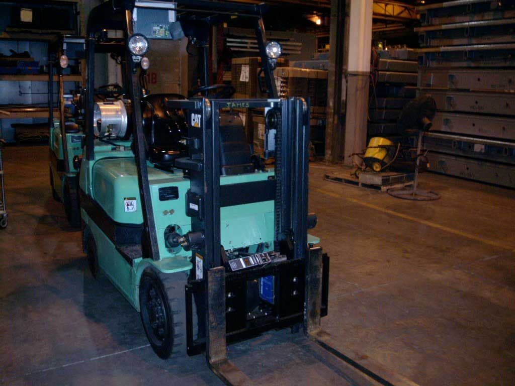
Click to zoom
Application Details
- Equipment Class
- DXT - Part 15 Low Power Transceiver, Rx Verified
- Date of Grant
- Apr 06, 2004
- Application Purpose
- Original Equipment
- Date of Application
- Apr 06, 2004
- Equipment Note
- Scale Controller, Model MCPC
- Frequency Range
- 902.00000000 - 928.00000000
- Country
- United States
Documents & Files
Document Text
Text extracted from the exhibit documents filed with the FCC. Open a document above to read the original.
Users Manual
CCSS0001 Forklift Scale Technical Manual 17082300A (2/04).00 © Mettler-Toledo, Inc. 2004 No part of this manual may be reproduced or transmitted in any form or by any means, electronic or mechanical, including photocopying and recording, for any purpose without the express written permission of Mettler-Toledo, Inc. U.S. Government Restricted Rights: This documentation is furnished with Restricted Rights. INTRODUCTION This publication is provided solely as a guide for individuals who have received Technical Training in servicing the METTLER TOLEDO product. METTLER TOLEDO RESERVES THE RIGHT TO MAKE REFINEMENTS OR CHANGES WITHOUT NOTICE. Precautions WARNING PERMIT ONLY QUALIFIED PERSONNEL TO SERVICE THIS EQUIPMENT. EXERCISE CARE WHEN MAKING CHECKS, TESTS, AND ADJUSTMENTS THAT MUST BE MADE WITH POWER ON. FAILING TO OBSERVE THESE PRECAUTIONS CAN RESULT IN BODILY HARM. READ this manual BEFORE operating or servicing this equipment. FOLLOW these instructions carefully. SAVE this manual for future reference. DO NOT allow untrained personnel to operate, clean, inspect, maintain, service, or tamper with this equipment. ALWAYS DISCONNECT this equipment from the power source before cleaning or performing maintenance. CALL METTLER TOLEDO for parts, information, and service. WARNING FOR CONTINUED PROTECTION AGAINST SHOCK HAZARD, CONNECT TO PROPERLY GROUNDED OUTLET ONLY. DO NOT REMOVE THE GROUND PRONG. WARNING DISCONNECT ALL POWER TO THIS UNIT BEFORE INSTALLING, SERVICING, CLEANING, OR REMOVING THE FUSE. FAILURE TO DO SO COULD RESULT IN BODILY HARM AND/OR PROPERTY DAMAGE. WARNING BEFORE CONNECTING/DISCONNECTING ANY INTERNAL ELECTRONIC COMPONENTS OR INTERCONNECTING WIRING BETWEEN ELECTRONIC EQUIPMENT, ALWAYS REMOVE POWER AND WAIT AT LEAST 30 SECONDS. FAILURE TO OBSERVE THESE PRECAUTIONS COULD RESULT IN BODILY HARM OR DAMAGE TO OR DESTRUCTION OF THE EQUIPMENT. CAUTION OBSERVE PRECAUTIONS FOR HANDLING ELECTROSTATIC SENSITIVE DEVICES. CAUTION BE SURE TO BLOCK THE LIFT BRACKET WHEN IT IS IN THE RAISED POSITION. OBSERVE ALL APPROPRIATE SAFETY PROCEDURES WHEN INSTALLING AND SERVICING THE SCALE. DANGER DO NOT REMOVE THE BOLTS FROM MORE THAN ONE FLEXURE AT A TIME WHILE THE CARRIAGE IS INSTALLED ON THE FORKLIFT. UNBOLTING MORE THAN ONE FLEXURE COULD RESULT IN BODILY HARM OR PROPERTY DAMAGE. DANGER IF USED IN A HAZARDOUS AREA, THE HAZARDOUS AREA MUST BE MADE SAFE PRIOR TO INSTALLATION, REPLACEMENT, OR TROUBLESHOOTING. FAILURE TO COMPLY COULD RESULT IN PERSONAL INJURY, DEATH, AND/OR PROPERTY DAMAGE. CAUTION CHANGES OR MODIFICATIONS NOT EXPRESSLY APPROVED BY METTLER TOLEDO COULD VOID THE AUTHORITY TO OPERATE THIS EQUIPMENT. Contents 1 Introduction....................................................................................................1-1 FCC Notice..........................................................................................................................1-2 2 Installation.....................................................................................................2-1 General..............................................................................................................................2-1 Tools....................................................................................................................................2-1 Install Scale Controller........................................................................................................2-1 Remove the Forklift Truck’s Lift Bracket.................................................................................2-2 Install the Scale Carriage....................................................................................................2-5 Batteries.............................................................................................................................2-8 Geo Index...........................................................................................................................2-9 Shift Adjustment..................................................................................................................2-9 3 Scale Operations............................................................................................3-1 Power-up Sequence.............................................................................................................3-1 Weighing Screen.................................................................................................................3-1 Push Buttons.........................................................................................................................3-2 Weighing Operations...........................................................................................................3-3 Gross Weighing....................................................................................................................3-3 Net Weighing with Push Button Tare.......................................................................................3-4 Net Weighing with Keyboard Tare...........................................................................................3-4 Accumulating Gross Weights..................................................................................................3-5 Accumulating Net Weights.....................................................................................................3-5 SmartWeigh Transactions......................................................................................................3-6 4 Scale Setup....................................................................................................4-1 Setup Screens.....................................................................................................................4-1 Scale..................................................................................................................................4-1 Filter............................................................................................…
Text truncated - open the document above for the full version.
Cover Letter(s)
The following non-conformities have been found. To continue evaluating this application please submit these items as soon as possible. If you have any questions, please do not hesitate to contact us. Thank you, Monika Brandle Item 1: Please submit a revised label following the FCC format as stated in Section 2.925. Example - FCC ID: XXX-123456. Also include on label the statements required per 15.19. - See attached documentation. Item 2: From the documentation provided, this would appear to be a modular device. If so, please provide a cover letter requesting modular approval and the MPE calculations (so that we can determine whether this is appropriate for a TCB to approve). If this is not the case, please provide documentation that clearly shows that this is not a modular device. - This is not a modular device. Item 3: From the documents provided, there are clocks lower than 30MHz. Please provide test data and equipment used showing compliance from 9kHz-30MHz and/or explain. - Addressed in new test report. No emissions of note. Item 4: Please provide a copy of the installation and operating instructions that will be furnished to the user. Note: include any antenna installation instructions. - See user guide. Item 5: Please provide a brief description of the circuit functions of the device along with a statement describing how the device operates. This should include a description of the ground system and antenna (if any). - See attached documentation Item 6: In a separate file, please provide a block diagram showing the frequency of all oscillators in the device. - See attached documentation. Item 7: I am unable to open the schematic files with a jpeg extension. Please resubmit using a pdf format if possible. Also, the FCC does not allow file sizes greater than 4MB. One of the files uploaded was 32MB. - Partly addressed. WHy can't you oprn jpegs? Item 8: Please provide a user manual showing the compliance statements required in section 15.21, 15.27, and 15.105. - See user guide. Item 9: From the test setup photos, it would appear that the antenna of the EUT is a non-removable integral antenna. Please confirm how this device complies with section 15.203. - The antenna in non removable. It is on a PCB inside the EUT enclosure. Section 15.203 does not apply. Item 10: If a device operates over a frequency range greater than 10MHz, then the frequency tested shall be located near the top, near the middle and near the bottom. From the data provided, testing was performed only on the middle channel. Please provide test data showing compliance to 15.249/15.209/15.205 for the top and bottom frequencies. - Addressed in new test report. Item 11: IAW 15.215, the EUT must be designed to ensure that the 20 dB bandwidth of the emission is contained within the frequency band designated in the rule section under which the equipment is operated. Please provide the appropriate band edge/occupied bandwidth plots to show compliance to the low and high frequency band edges. - Addressed in new test report.
External Photos
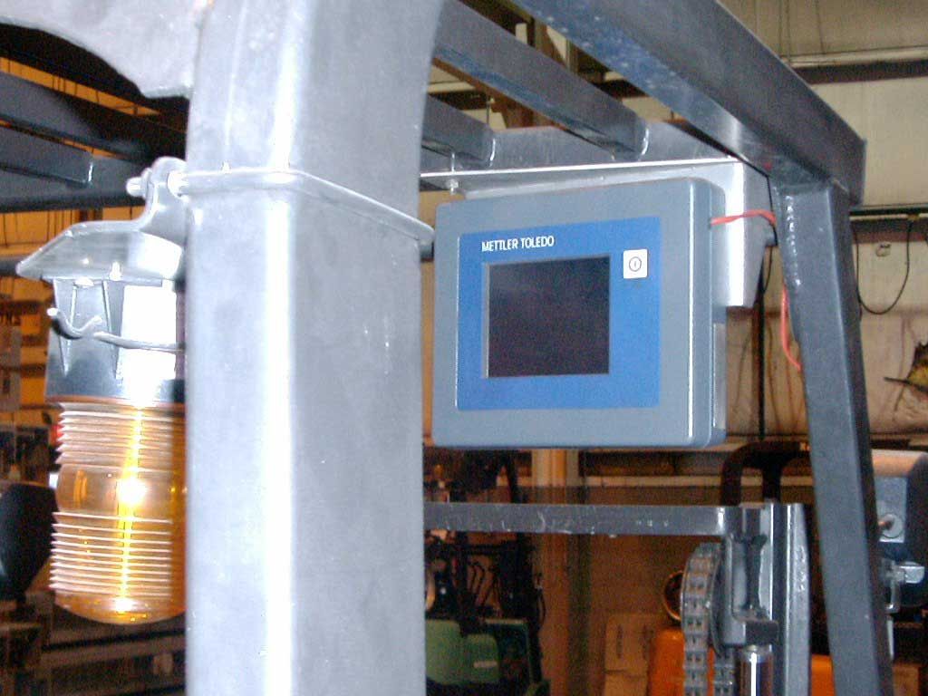
Mettler Toledo MCPC – External Photographs PHOTOGRAPH OF EUT – Front View PHOTOGRAPH OF EUT – Back View
ID Label/Location Info
MCPC20 1. Print Data Label ( 14115500A ) and install as shown on Rear Casting. 2. Install Clear Shield ( 14115600A ) over Data Label. Data Label & Clear Shield
ID Label/Location Info
METTLER TOLEDO DOCUMENT NO. 168661R 168661R168661R 168661R THIS DOCUMENT CONTAINS CONFIDENTIAL AND PROPRIETARY INFORMATION OF METTLER-TOLEDO, INC. THE CONTENTS HEREOF MAY NOT BE USED NOR REPRODUCED IN WHOLE OR IN PART WITHOUT THE WRITTEN AUTHORIZATION OF METTLER-TOLEDO, INC. COPYRIGHT 2003 METTLER-TOLEDO, INC. SUPERSEDES TITLE INFO, DATA LABEL, MODEL MCPC DESCRIPTION RECORD OF CHANGES CHG. NO. DESCRIPTION BY APVD. ER NO. DATE 0 RELEASED DER KBN 62778 08/03 1 ADD FCC ID NO. AND WORDING. DER KBN 62932 09/03 2 ADD UR LOGO. DER KBN 63096 11/03 3 Add a ‘:’ after FCC ID & CC number 03-105. DER KBN 63456 02/04 NOTES: 1. SERIAL NUMBER COMPUTER GENERATED. 2. USE SONY CHEMICALS CORPORATION OF AMERICA RIBBON #TR4070. TYPE 1 Factory Market Number Number 000 MCPC-0001 TYPE 1
Internal Photos
Mettler Toledo MCPC – Internal Photographs Photograph of EUT – Main Board (Component Side View) Photograph of EUT – Main Board (Solder Side View) Mettler Toledo MCPC – Internal Photographs Photograph of EUT – Inside View Photograph of EUT – Chassis (Inside View) Mettler Toledo MCPC – Internal Photographs Photographs of EUT – Radio Module Detail Mettler Toledo MCPC – Internal Photographs Mettler Toledo MCPC – Internal Photographs
Test Report
This report shall not be duplicated except in full without the written approval of F-Squared Laboratories. EMC007 Rev. 1 Report Number: CLE091702-01-03E, Revision 1 Page 1 of 19 Issue Date: June 16, 2004 F-Squared Laboratories 14333Kinsman Road Burton, OH 44021 (440) 834-8926 Fax: (440) 834-8914 For a Scale Controller Manufacturer: Laboratory: Mettler Toledo F-Squared Laboratories 6600 Huntley Road 16740 Peters Road Columbus, OH 43229 Middlefield, Ohio 44062 United States of America United States of America The Scale Controller, model MCPC, has been tested and found to comply with the requirements of the Federal Communications Commission outlined in the Federal Register CFR 47, Part 15, subpart C. The product was received on September 12, 2003 and the testing was completed on January 28, 2004. Certification Test Report Client: Mettler Toledo Order Number: CLE091702-01 Model: MCPC EMC007 Rev. 1 Report Number: CLE091702-01-03E, Revision 1 Page 2 of 19 Issue Date: June 16, 2004 Table of Contents Exhibit Title Page Cover Page 1 Table of Contents 2 I Engineering Statement 3 II Measurement Instrument List 5 III EUT Information 6 IV EUT Configuration and Cables 7 V Radiated Data 8 VI Band Occupancy 10 VII EUT Photos 12 Client: Mettler Toledo Order Number: CLE091702-01 Model: MCPC EMC007 Rev. 1 Report Number: CLE091702-01-03E, Revision 1 Page 3 of 19 Issue Date: June 16, 2004 Exhibit I Engineering Statement This report has been prepared on behalf of Mettler Toledo to provide documentation for the testing described herein. This equipment has been tested and found to comply with Part 15, subpart C of the FCC Rules and under the regulation section 15.249 and section 15.209 procedures, using ANSI C63.4 1992 standards. The test results found in this report relate only to the items tested. E QUIPMENT UNDER TEST: Scale Controller Trade Name: Mettler Toledo FCC ID: RITSC0001 Model No.: MCPC Power Supply: 12 VDC Battery A PPLICABLE RULES: CFR 47, Part 15, subpart C E QUIPMENT CATEGORY: Intentional Radiator M EASUREMENT LOCATION: F-Squared Laboratories in Middlefield, Ohio. Site description and attenuation data are on file with the FCC's Sampling and Measurement Branch at the FCC Laboratory in Columbia, MD. M EASUREMENT PROCEDURE: All measurements were performed according to the 1992 version of ANSI C63.4. A list of the measurement equipment can be found in Exhibit II. Client: Mettler Toledo Order Number: CLE091702-01 Model: MCPC EMC007 Rev. 1 Report Number: CLE091702-01-03E, Revision 1 Page 4 of 19 Issue Date: June 16, 2004 U NCERTAINTY BUDGET: • Radiated Emission Combined Uncertainty (+ or -) 2.24 dB Expanded Uncertainty (+ or -) 4.48 dB • Conducted Emission Combined Uncertainty (+ or -) 1.13 dB Expanded Uncertainty (+ or -) 2.26 dB E NGINEERING STATEMENT: I hereby state that: The measurements shown in this application were made in accordance with the procedures indicated and the energy emitted by this equipment was found to be within the limits. I assume full responsibility for the accuracy and completeness of these measurements. I further state that: On the basis of the measurements made, the equipment tested is capable of operation in accordance with the requirements of Part 15 of the FCC Rules under normal use and maintenance. Certified by: _____________________________________ John Harrington, EMC Technical Manager Client: Mettler Toledo Order Number: CLE091702-01 Model: MCPC EMC007 Rev. 1 Report Number: CLE091702-01-03E, Revision 1 Page 5 of 19 Issue Date: June 16, 2004 Exhibit II List of Measurement Instrumentation Equipment Type Manufacturer Model Serial Number Calibration Due Date OATS Compliance Labs N/A 001 Oct. 8, 2004 Receiver Dynamic Sciences DSI-2020 604/002 Sept. 4, 2004 Chamber Antenna 1 EMC Test Systems 3143 Biconilog 9603-1229 June 12, 2004 OATS Antenna 2 EMC Test Systems 3143 Biconilog 9609-1306 July 25, 2004 Pre Amp Hewlett Packard 83006A 3104A00500 Sept. 9, 2004 Spectrum Analyzer Hewlett Packard 8566B 2311A02270 Nov. 4, 2004 Active Loop Antenna AH Systems SAS-562B 232 Nov. 14, 2004 Horn Antenna EMCO 3115 9809-5580 Feb. 6, 2005 Client: Mettler Toledo Order Number: CLE091702-01 Model: MCPC EMC007 Rev. 1 Report Number: CLE091702-01-03E, Revision 1 Page 6 of 19 Issue Date: June 16, 2004 Exhibit III EUT Information TEST ITEM CONDITION: The equipment to be tested was received in good condition. TESTING ALGORITHM: The EUT was powered on using a fully charged battery and was operated using software in a test mode that made it transmit with a constant carrier. The fundamental emissions, harmonic emissions up to the 10 th harmonic and the other spurious emissions are recorded in the data tables. R ADIATED EMISSION TESTING: The emissions were maximized by rotating the table and raising/lowering the antenna mounted on a 4.0 meter mast. Cable and peripheral positions were also varied to produce maximum emissions. Both horizontal and vertical field components were measured. The output of the antenna was connected to the input of the receiver and emissions were measured in the range 9kHz to 10GHz. The measurement detector, bandwidth and distance are detailed in the table below. The raw measurements were corrected to allow for antenna factor and cable loss. All data for radiated emissions can be found in Exhibit V. Frequency Range Detector Resolution Bandwidth Distance 9kHz to 150kHz Quasi-Peak 200Hz 3.0m 150kHz to 30MHz Quasi-Peak 10kHz 3.0m 30MHz to 1GHz Quasi-Peak 120kHz 3.0m 1GHz to 10GHz Peak 1MHz 3.0m Client: Mettler Toledo Order Number: CLE091702-01 Model: MCPC EMC007 Rev. 1 Report Number: CLE091702-01-03E, Revision 1 Page 7 of 19 Issue Date: June 16, 2004 Exhibit IV EUT Configuration and Cables Equipment Under Test (EUT): Device Manufacturer Model Number Serial Number Scale Controller Mettler Toledo MCPC None Accessories (Support Equipment): Device Manufacturer Model Number Serial Number 12 VDC Battery Panasonic LC-LC1233P N/A Cables: Cable Function Length Shielded (Yes/No) DC Power 1 mete…
Text truncated - open the document above for the full version.
Test Setup Photos
RADIATED TEST RADIATED TEST
Contact Information
Applicant
Thomas S. Rice(R&D Manager)
Technical Contact
F-Squared LaboratoriesRob Pellizze
[email protected]301-253-4500
9890 Main Street · Damascus, Maryland · United States
Non-Technical Contact
F-Squared LaboratoriesMona Boersen
[email protected]301-253-4500
Test Firm
F-Squared LaboratoriesWendy Fuster
Technical Specifications
| # | Rule Parts | Frequency Range | Power Output |
|---|---|---|---|
| 1 | 15C | 902 MHz - 928 MHz | - |
Other Applications from Mettler-Toledo, Inc. Heavy Industrial PO
RITTE0002
Mar 15, 2005WIRELESS FORKLIFT SCALE
Equipment Class
DXT - Part 15 Low Power Transceiver, Rx Verified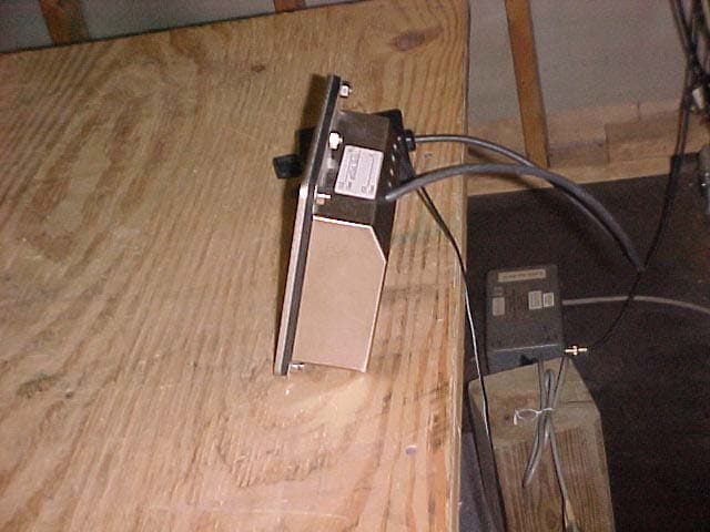
RITTE0001
Apr 07, 2004Scale Carriage, Model MCSB
Equipment Class
DXT - Part 15 Low Power Transceiver, Rx Verified