RJ6ET1000SBluetooth Wireless Headset
Tekkeon, Inc.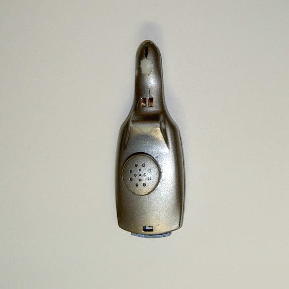
Click to zoom
Application Details
- Equipment Class
- DSS - Part 15 Spread Spectrum Transmitter
- Date of Grant
- Nov 18, 2003
- Application Purpose
- Original Equipment
- Date of Application
- Nov 18, 2003
- Equipment Note
- Bluetooth Wireless Headset
- Frequency Range
- 2402.00000000 - 2480.00000000
- Company
- Tekkeon, Inc.
- Country
- United States
Documents & Files
Document Text
Text extracted from the exhibit documents filed with the FCC. Open a document above to read the original.
Users Manual
1 USER GUIDE ET1000 Figure 1. ezTalker inserted into charging cradle EZTALKER by Tekkeon is a sleek cord-free headset that enables comfortable handsfree communication with your mobile phone. EZTALKER 1000 works with your Bluetooth-ready mobile phone to provide clear, high-quality communication. While using your EZTALKER headset, you can store your mobile phone in your pocket, backpack, or briefcasejust about anywhere in close proximity that is convenient for you. Unpacking EZTALKER Your ezTalker package includes the following: ! ezTalker Headset " Charging cradle with belt clip # Charger % ezEarhook & ezFit Ring ' Comfort Pad ( User guide (not shown) Getting to Know EZTALKER Getting Started Before using ezTalker, you must: ) Charge ezTalker ) Pair ezTalker to your mobile phone ) Fit ezTalker to your ear ) Power ezTalker Directions for each of these activities are provided in the following four sections. Once these steps are completed, you will be ready to use ezTalker! Charging EZTALKER Before using ezTalker, you must charge the headset for approximately two hours. When fully charged, the battery provides up to four hours of talk time and up to 168 hours of standby time. To Charge the Headset 1. Insert ezTalker into the charging cradle as shown. 2. Plug the charger into the charging jack on the right side of the charging cradle. 3. Plug the charger into a wall outlet. While the headset is charging, the amber LED on the headset will remain on. When the headset is fully charged, the amber LED will turn off. 4. Unplug the charger cable from the wall outlet and the charging cradle. BATTERY INDICATION: When the battery is low (less than 10% of capacity), the amber LED will flash and youíll hear a double beep every 32 seconds. Pairing EZTALKER to Your Mobile Phone Pairing is the process of linking the headset with your Bluetooth mobile phone. Before using ezTalker with your mobile phone you must pair the devices. After this process is complete, you can use the headset only with its paired mobile phone. To use ezTalker with a different mobile phone, you must repeat the pairing process with the new mobile phone. In this case, the headset will no longer work with the original mobile phone. BEFORE YOU PAIR THE HEADSET, ENSURE THAT THE BATTERY IS FULLY CHARGED, AND REVIEW THE INSTRUCTIONS IN YOUR MOBILE PHONE USER GUIDE FOR PAIRING YOUR MOBILE PHONE TO A BLUETOOTH HEADSET . To Pair the Devices 1. Turn on the mobile phone and place it within 10 feet of the headset. 2. Initiate the Bluetooth device-pairing (discovery) feature on the mobile phone. Refer to the mobile phone user guide for instructions on initiating this feature. 3. With the headset turned off, press and hold the TALK button approximately five seconds, until the blue and amber LEDs flash alternately or until you hear the PAIRING tone. 4. Release the TALK button. The headset is now in Pairing Mode. 5. Follow the mobile phone prompts, and when prompted for the passkey (also called passcode or BT PIN), enter 0000 (the ezTalker passkey). When pairing is complete, the headset will be placed in Standby Mode, ready to make and receive calls, the amber LED will turn off, and the blue LED will flash at two-second intervals. ! TALK Button Used for turning headset on/off, pairing, and making/receiving calls Volume Control Used to adjust the speaker volume and to mute the microphone Amber and Blue LEDs Provides visual indication of headset status: power on/off, pairing mode, muting mode, charging mode, and low batter y Microphone Speaker " # % & ' 2 USER GUIDE Figure 4. ezEarhook connected for right and left ears Figure 2. ezTalker with ezFit Ring Figure 3. ezTalker with Comfort Pad To Cancel Pairing Mode While you are in pairing mode, you can cancel the pairing process and turn off the headset. 1. While in pairing mode, press and hold the TALK button approximately three seconds until both LEDs turn off or you hear the OFF tone. Fitting EZTALKER On Your Ear EzTalker is designed to fit comfortably in your ear. For added comfort, you can add the optional ezEarhook , ezFit Ring, and/or comfort foam pad. For additional comfort, you can add the comfort foam pad that is included with ezTalker. To Place the Headset On Your Ear 1. Place the ezTalker speaker in your ear with the microphone angled toward your mouth as shown. The headset should fit snugly in your ear and remain in your ear when you move your head. However, if the speaker is too small for your ear, you can add the ezFit Ring that is provided with your headset. To Add the ezFit Ring 1. Stretch the ezFit Ring around the end of the microphone as shown. To Add the Comfort Pad 1. Stretch the comfort pad around the end of the microphone as shown. The comfort pad can be placed over the ezFit Ring, if both are needed. To Add the ezEarhook 1. Right ear: From the rear of ezTalker, insert the bottom of the ezEarhook into the small hole on the left side of the headset, pushing until it stops. Left ear: From the rear of ezTalker, insert the bottom of the ezEarhook into the small hole on the right side of the headset, pushing until it stops. 2. You can mold the soft plastic on ezEarhook to better fit your ear, and/or adjust the placement of the ezEarhook stem through the headset (further in/out). To Remove the ezEarhook 1. Gently pull the ezEarhook away from the headset until it separates from the headset. Powering ezTalker To Turn On the Headset Press and hold the TALK button approximately four seconds until the blue LED flashes or until you hear the ON tone. The headset turns on and is placed in standby mode, ready to make and receive calls. While the headset is on and in standby mode, the blue LED will flash at two- second intervals. To Turn Off the Headset When the headset is on, press and hold the TALK button approximately four seconds until the blue LED turns off or until you hear the OFF tone. The headset turns off. Making Calls You can make calls from your mobile phone, or directly from ezTalker us…
Text truncated - open the document above for the full version.
Users Manual
1 USER GUIDE ET1500 Figure 1. ezTalker inserted into audio gateway EZTALKER by Tekkeon is a sleek cordless headset that enables comfortable handsfree communication with your cell phone. EZTALKER 1500 comes with an audio gateway that connects your non-Bluetooth ready cell phone to provide clear, high-quality communication. Unpacking EZTALKER Your ezTalker package includes the following: ! ezTalker Headset " Audio gateway/charging cradle with belt clip # Charger % ezEarhook & ezFit Ring ' Comfort foam pad ( Nokia adapter cable ) 2.5 mm adapter cable * Nokia pop-port adapter + User guide (not shown) Getting to Know EZTALKER EZTALKER Headset Audio Gateway Getting Started Before using ezTalker, you must: , Charge ezTalker , Pair ezTalker to the audio gateway , Connect your cell phone to the audio gateway , Fit ezTalker to your ear , Power ezTalker Directions for each of these activities are provided in the following five sections. Once these steps are completed, you will be ready to make and receive calls with ezTalker! Charging EZTALKER Before using ezTalker, you must charge the headset for approximately two hours. When fully charged, the battery provides up to four hours of talk time and up to 168 hours of standby time. To Charge the Headset 1. Insert ezTalker into the audio gateway as shown. 2. Plug the charger into the charging jack on the right side of the audio gateway. 3. Plug the charger into a wall outlet. While the headset is charging, the amber LEDs on the headset and audio gateway will remain on. When the headset is fully charged, the amber LEDs will turn off. 4. Unplug the charger cable from the wall outlet and the audio gateway. BATTERY INDICATION: When the battery is low (less than 10% of capacity), the amber headset LED will flash and youíll hear a double beep every 32 seconds. Pairing EZTALKER to the Audio Gateway Pairing is the process of linking the headset with the audio gateway that is, in turn, connected to your cell phone. Before using ezTalker with your cell phone you must pair the devices. After this process is complete, you can use the headset only with its paired audio gateway. BEFORE YOU PAIR THE HEADSET, ENSURE THAT THE BATTERY IS FULLY CHARGED. To Pair the Devices 1. With the headset turned off, press and hold the TALK button approximately five seconds, until the blue and amber LEDs flash alternately or until you hear the PAIRING tone. 2. Release the TALK button and immediately perform the next step. The headset is now in Pairing Mode. 3. With the audio gateway turned off, press and hold the POWER button approximately five seconds, until the blue and amber LEDs flash alternately. ! " # % & ' TALK Button Used for turning headset on/off, pairing, and making/receiving calls Volume Control Used to adjust the speaker volume and to mute the microphone Amber and Blue LEDs Provides visual indication of headset status: power on/off, pairing mode, muting mode, charging mode, and low battery Microphone Speaker ( ) * POWER Button Used for turning audio gateway on/off, and to initiate pairing Amber/Blue LEDs Provide visual indication of audio gateway status: power on/off, pairing mode, charging mode, and call connections Charger Jack For connection of charger Audio Jack For connection of adapter cable to cell phone 2 USER GUIDE Figure 5. ezEarhook connected for right and left ears Figure 3. ezTalker with ezFit Ring Figure 4. ezTalker with Comfort Pad Figure 2. Nokia pop-port 4. Release the POWER button. The audio gateway is now in Pairing Mode. When pairing is complete, the headset will be placed in standby mode, ready to make and receive calls, the amber LEDs on both devices will turn off, and the blue LED on the headset will flash at two-second intervals. To Cancel Pairing Mode While you are in pairing mode, you can cancel the pairing process and turn off the headset. 1. While in pairing mode, press and hold the TALK button approximately three seconds until both LEDs turn off or you hear the OFF tone. Connecting the Audio Gateway to Your Cell Phone The audio gateway enables cell phones that are not Bluetooth-ready to take advantage of the ezTalker cordless Bluetooth headset. While you use the headset, your cell phone must be connected to the audio gateway through the cell phoneís headset jack. As each cell phone accepts a different type of headset connector, ezTalker comes with adapters for the three most common headset connectors: Nokia adapter cable (fits Nokia 3360/3390/6500/8200/8300/8800 series), pop-port adapter (fits Nokia 3300 phone and Nokia 2200/2270/2285/3580/ 5100/6100/6800/7200/9290 series phones with pop-port as shown in Figure 2), and 2.5 mm adapter cable (fits cell phones with a 2.5mm headset port). To Connect Your Nokia 3360/3390/6500/8200/8300/8800 Series Cell Phone to the Audio Gateway (Using the cable with two gray ends) 1. Connect one end of the Nokia adapter cable into the headset jack on your cell phone. 2. Connect the opposite end of the cable into the audio jack on the left side of the audio gateway. To Connect Your Nokia Cell Phone with a Pop-Port to the Audio Gateway (Using the cable with one gray and one black end) 1. Connect the pop-port adapter into the pop-port on your cell phone. 2. Connect the black end of the 2.5 mm adapter cable into the headset jack on the pop-port adapter. 3. Connect the gray end of the cable into the jack on the left side of the audio gateway. To Connect Your Cell Phone with 2.5 mm Headset Port to the Audio Gateway (Using the cable with one gray and one black end) 1. Connect the black end of the 2.5 mm adapter cable into the headset jack on your cell phone. 2. Connect the gray end of the cable into the jack on the left side of the audio gateway. Fitting EZTALKER On Your Ear EzTalker is designed to fit comfortably in your ear. For added comfort, you can add the optional ezEarhook , ezFit Ring, and/or comfort foam pad. To Place the Headset On Your Ear 1. Place the ezTalker speaker in your ear with the microphone angled to…
Text truncated - open the document above for the full version.
Cover Letter(s)
Page 1 of 2 RE: Tekkeon FCC ID: RJ6ET1000S 1) Please provide top bottom photographs of the Bluetooth Module by itself and photographs of the main board without the module attached. Response: Photos have been upload 2) A schematic for the TX portion of the device is required as specified 2.1033(b)(5) for the RF section. However, if the TX portion of this device is an OEM part provided by another manufacturer, as an alternative, you may provide a parts list that lists that shows that this part is provided by another manufacturer. Please provide either a schematic for the TX or parts list as specified. Response: Schematics of transmitter bluetooth module uploaded. 3) The users manual appears to be missing the statements required by 15.21. Please correct. Response: Statement has been place on the manual page 4 of 4. 4) Please provide units for the table located on page 11 of 20 for the output power. Additionally it is not certain what method was applied (far field equations, substitution, etc.). Additionally, is the power calculated for conducted power, ERP, or EIRP. Response: Units have been included. Method of far field equations was used by using the following formula to calculated the field strength EIRP and convert to dBm EIRP: Calculation Of Effective Radiated Power From Radiated Field Strength In order to determine the transmit power from an intentional radiator with no external antenna it is necessary to use the radiated field strength. The calculation uses the following formula: E = v(30.P.G) d Where: E is the radiated field strength in V/m; P is the power transmitted in Watts; G is the gain of the transmit antenna; d is the distance from the transmitter at which field strength E was recorded Rearranging gives: P = E 2 .d 2 30.G Converting to logarithmic units (multiplication becomes addition, division becomes subtraction) gives: Page 2 of 2 P dB(W) = E dB(V/m) + 20log10 (d) - 10log 10 (30) - 10log 10 (G). For the purposes of calculating the effective radiated power the unit under test is assumed to have unity gain (i.e. 0dB). so: P dB(W) = E dB(V/m) + 20log10 (d) - 10log 10 (30) To convert dBm to dB(W) subtract 30, to convert dB(μV/m) to dB(V/m) subtract 120, giving: P dBm - 30 = E dB(μV/m) - 120 + 20log10 (d) - 10log 10 (30) Substitute for 10log 10 (30) gives P dBm - 30 = E dB(μV/m) -120 + 20log10 (d) - 14.77 For d = 3m the final calculation is: P dBm = E dB(μV/m) -120 + 9.5 - 14.77 +30 P dBm = E dB(μV/m) - 95.27 If the unit has an antenna of gain GdB attached when taking the field strength measurement then you adjust the value of P above by subtracting G. 5) Information given on page 12 appears to be partially incorrect. The maximum dwell time should be in a 30 second period of time given the nature of this signal (< 1 MHz bandwidth), not 10 second. Please carefully review the results of this page. Response: This has been corrected to 30 seconds. Revised report has been revised and uploaded. 6) The data given on page 16 of 20 appears to suggest that the EUT is transmitting on frequencies from 2390 to 2393 and 2483.5 to 2486.50 or is otherwise unclear what was originally measured and using what bandwidths. Note that transmission below 2.4 GHz and above 2.4835 GHz is not allowed. Please clarify the table. Response: This has been corrected and revised. New revised report has been uploaded. Regards, Juan Martinez Sr. EMC Engineer
Cover Letter(s)
Page 1 of 2 RE: Tekkeon FCC ID: RJ6ET1000S 1) Only one of the users manuals provided was updated for the missing the statements required by 15.21. Please correct both manuals. Response: Second manual uploaded with 15.21 statement. 2) Note that Run #3 has labeled all channels as LOW. This likely should have been LOW, MIDDLE, and HIGH. Response: This has been corrected. 3) Has the antenna of this device been quantified for gain as 0 dBi? If not, please provide additional information using the substitution method to support the power measurements provided. Response: Per client the gain is about 2dBi. The stated conducted power is 4dBm + 2dBi = 6 dBm EIRP (6.07dBm is the reported EIRP power). Per OET 63 (Page 29) states another formula to use for low power non-license transmitters. Using this equation, and assuming a unity gain antenna (G = 1) for EIRP or (G = 1.64) for ERP and a measurement distance of 3 meters (D = 3), a formula for determining power given field strength can be developed: P=0.3*E^2 Where: P = power in watts EIRP E = Field strength in V/m So: 101.37 dBuV/m = 0.117 V/m P = 0.3 * (0.117)^2 P = 0.004113 Watts P = 6.14 dBm (EIRP) The formula we used: P = E (dBuV/m) - 95.3dB Where: P = power in dBm E = Field strength in dBuV/m So: P = 101.37 – 95.3dB P = 6.07 dBm (EIRP) The difference between this equation and formula we use is about 0.07 dB differences. Per the client the power cannot be measured directly due to mismatch impedance problems. Page 2 of 2 Anything else please let me know. Regards, Juan Martinez Sr. EMC Engineer
Cover Letter(s)
American Telecommunications Certification Body Inc. 6731 Whittier Ave, McLean, VA 22101 November 17, 2003 RE: Tekkeon FCC ID: RJ6ET1000S I have a few comments on the above referenced Application. 1) Please provide top bottom photographs of the Bluetooth Module by itself and photographs of the main board without the module attached. 2) A schematic for the TX portion of the device is required as specified 2.1033(b)(5) for the RF section. However, if the TX portion of this device is an OEM part provided by another manufacturer, as an alternative, you may provide a parts list that lists that shows that this part is provided by another manufacturer. Please provide either a schematic for the TX or parts list as specified. 3) The users manual appears to be missing the statements required by 15.21. Please correct. 4) Please provide units for the table located on page 11 of 20 for the output power. Additionally it is not certain what method was applied (far field equations, substitution, etc.). Additionally, is the power calculated for conducted power, ERP, or EIRP. 5) Information given on page 12 appears to be partially incorrect. The maximum dwell time should be in a 30 second period of time given the nature of this signal (< 1 MHz bandwidth), not 10 second. Please carefully review the results of this page. 6) The data given on page 16 of 20 appears to suggest that the EUT is transmitting on frequencies from 2390 to 2393 and 2483.5 to 2486.50 or is otherwise unclear what was originally measured and using what bandwidths. Note that transmission below 2.4 GHz and above 2.4835 GHz is not allowed. Please clarify the table. Timothy R. Johnson Examining Engineer mailto: [email protected] The items indicated above must be submitted before processing can continue on the above referenced application. Failure to provide the requested information may result in application termination. Correspondence should be considered part of the permanent submission and may be viewed from the Internet after a Grant of Equipment Authorization is issued. Please do not respond to this correspondence using the email reply button. In order for your response to be processed expeditiously, you must submit your documents through the AmericanTCB.com website. Also, please note that partial responses increase processing time and should not be submitted. Any questions about the content of this correspondence should be directed to the sender.
Cover Letter(s)
American Telecommunications Certification Body Inc. 6731 Whittier Ave, McLean, VA 22101 November 19, 2003 RE: Tekkeon FCC ID: RJ6ET1000S I have a few comments on the above referenced Application. 1) Only one of the users manuals provided was updated for the missing the statements required by 15.21. Please correct both manuals. 2) Note that Run #3 has labeled all channels as LOW. This likely should have been LOW, MIDDLE, and HIGH. 3) Has the antenna of this device been quantified for gain as 0 dBi? If not, please provide additional information using the substitution method to support the power measurements provided. Timothy R. Johnson Examining Engineer mailto: [email protected] The items indicated above must be submitted before processing can continue on the above referenced application. Failure to provide the requested information may result in application termination. Correspondence should be considered part of the permanent submission and may be viewed from the Internet after a Grant of Equipment Authorization is issued. Please do not respond to this correspondence using the email reply button. In order for your response to be processed expeditiously, you must submit your documents through the AmericanTCB.com website. Also, please note that partial responses increase processing time and should not be submitted. Any questions about the content of this correspondence should be directed to the sender.
ID Label/Location Info
Tekkeon, Inc. ezTalker FCC ID location The “FCC ID: RJ6ET1000S” will be etched on the surface area indicated as 17mm x 5mm
Internal Photos
Core Bluetooth Module top Core Bluetooth Module bottom Headset Module top side Headset Module bottom side
Operational Description
BLUETOOTH APPROVALS The following exhibit indicates the FCC Spread Spectrum requirements in Section 15.247 for devices meeting the Bluetooth Specifications in the 2.4 GHz band as of February 2001 operating in the USA. The purpose of this exhibit is to help expedite the approval process for Bluetooth devices. This exhibit provides items that vary for each device and also provides a list of items that are common to Bluetooth devices that explains the remaining requirements. The list of common items can be submitted for each application for equipment authorization. This exhibit only specifies requirements in Section 15.247, requirements in other rule Sections for intentional radiators such as in Section 15.203 or 15.207 must be also be addressed. For each individual device, the following items, 1-7 will vary from one device to another and must be submitted. 1) The occupied bandwidth in Section 15.247(a)(1)(ii). 2) Conducted output power specified in Section 15.247(b)(1). 3) EIRP limit in Section 15.247(b)(3). 4) RF safety requirement in Section 15.247(b)(4) 5) Spurious emission limits in Section 15.247©. 6) Processing gain and requirements for Hybrids in Section 15.247(f) in the acquisition mode. 7) Power spectral density requirement in Section 15.247(f) in the acquisition mode. For all devices, the following items, 1-12, are common to all Bluetooth devices and will not vary from one device to another. This list can be copied into the filing. 1 Output power and channel separation of a Bluetooth device in the different operating modes: The different operating modes (data-mode, acquisition-mode) of a Bluetooth device don’t influence the output power and the channel spacing. There is only one transmitter which is driven by identical input parameters concerning these two parameters. Only a different hopping sequence will be used. For this reason, the RF parameters in one op-mode is sufficient. 2 Frequency range of a Bluetooth device: The maximum frequency of the device is: 2402 – 2480 MHz. This is according the Bluetooth Core Specification V 1.0B (+ critical errata) for devices which will be operated in the USA. Other frequency ranges ( e.g. for Spain, France, Japan) which are allowed according the Core Specification must not be supported by the device. 3 Co-ordination of the hopping sequence in data mode to avoid simultaneous occupancy by multiple transmitters: Bluetooth units which want to communicate with other units must be organized in a structure called piconet. This piconet consist of max. 8 Bluetooth units. One unit is the master the other seven are the slaves. The master co-ordinates frequency occupation in this piconet for all units. As the master hop sequence is derived from it’s BD address which is unique for every Bluetooth device, additional masters intending to establish new piconets will always use different hop sequences. 4 Example of a hopping sequence in data mode: Example of a 79 hopping sequence in data mode: 40, 21, 44, 23, 42, 53, 46, 55, 48, 33, 52, 35, 50, 65, 54, 67, 56, 37, 60, 39, 58, 69, 62, 71, 64, 25, 68, 27, 66, 57, 70, 59, 72, 29, 76, 31, 74, 61, 78, 63, 01, 41, 05, 43, 03, 73, 07, 75, 09, 45, 13, 47, 11, 77, 15, 00, 64, 49, 66, 53, 68, 02, 70, 06, 01, 51, 03, 55, 05, 04 5 Equally average use of frequencies in data mode and short transmissions: The generation of the hopping sequence in connection mode depends essentially on two input values: 1. LAP/UAP of the master of the connection 2. Internal master clock The LAP (lower address part) are the 24 LSB’s of the 48 BD_ADDRESS. The BD_ADDRESS is an unambiguous number of every Bluetooth unit. The UAP (upper address part) are the 24 MSB’s of the 48 BD_ADDRESS. The internal clock of a Bluetooth unit is derived from a free running clock which is never adjusted and is never turned off. For synchronization with other units, only the offsets are used. It has no relation to the time of the day. Its resolution is at least half the RX/TX slot length of 312.5 μs. The clock has a cycle of about one day (23h30). In most case it is implemented as 28 bit counter. For the deriving of the hopping sequence the entire LAP (24 bits), 4 LSB’s (4 bits) (Input 1) and the 27 MSB’s of the clock (Input 2) are used. With this input values different mathematical procedures (permutations, additions, XOR-operations) are performed to generate the sequence. This will be done at the beginning of every new transmission. Regarding short transmissions, the Bluetooth system has the following behavior: The first connection between the two devices is established, a hopping sequence is generated. For transmitting the wanted data, the complete hopping sequence is not used and the connection ends. The second connection will be established. A new hopping sequence is generated. Due to the fact that the Bluetooth clock has a different value, because the period between the two transmission is longer (and it cannot be shorter) than the minimum resolution of the clock (312.5 μs). The hopping sequence will always differ from the first one. 6 Receiver input bandwidth, synchronization and repeated single or multiple packets: The input bandwidth of the receiver is 1 MHz. In every connection, one Bluetooth device is the master and the other one is the slave. The master determines the hopping sequence (see chapter 5). The slave follows this sequence. Both devices shift between RX and TX time slot according to the clock of the master. Additionally the type of connection (e.g. single or multi-slot packet) is set up at the beginning of the connection. The master adapts its hopping frequency and its TX/RX timing is according to the packet type of the connection. Also, the slave of the connection uses these settings. Repeating of a packet has no influence on the hopping sequence. The hopping sequence generated by the master of the connection will be followed in any case. That means, a repeated packet will not be send on the same frequency, it is send on the next frequency …
Text truncated - open the document above for the full version.
Test Report
File: R53415 Page 1 of 18 Electromagnetic Emissions Test Report and Application for Grant of Equipment Authorization pursuant to FCC Part 15, Subpart C (15.247) DTS Specifications and Industry Canada RSS 210 Issue 5 for an Intentional Radiator on the Tekkeon Model: ezTalker FCC ID: RJ6ET1000S GRANTEE: Tekkeon 3002 Dow Ave, Ste 218 Tustin, CA. 92780 TEST SITE: Elliott Laboratories, Inc. 684 W. Maude Avenue Sunnyvale, CA 94086 REPORT DATE: November 12, 2003 FINAL TEST DATE: November 4 and November 7, 2003 AUTHORIZED SIGNATORY: ______________________________ Juan Martinez Senior EMC Engineer Elliott Laboratories, Inc. is accredited by the A2LA, certificate number 2016-01, to perform the test(s) listed in this report. This report shall not be reproduced, except in its entirety, without the written approval of Elliott Laboratories, Inc. Elliott Laboratories, Inc. -- EMC Department Test Report Report Date: November 12, 2003 File: R53415 Page 2 of 18 Pages TABLE OF CONTENTS COVER PAGE..................................................................................................................................................................................1 APPLICATION AND AGREEMENT FOR CERTIFICATION SERVICES.........................................................................1 TABLE OF CONTENTS...............................................................................................................................................................2 SCOPE.............................................................................................................................................................................................4 OBJECTIVE...................................................................................................................................................................................4 SUMMARY OF RESULTS...........................................................................................................................................................5 MEASUREMENT UNCERTAINTIES....................................................................................................................................6 EQUIPMENT UNDER TEST (EUT) DETAILS..........................................................................................................................7 GENERAL...................................................................................................................................................................................7 ENCLOSURE..............................................................................................................................................................................7 MODIFICATIONS....................................................................................................................................................................7 SUPPORT EQUIPMENT...............…
Text truncated - open the document above for the full version.
Contact Information
Applicant
Jerry Yang(President)
Technical Contact
Elliott Laboratories Inc.Juan Martinez
[email protected]408-245-7800
684 West Maude Ave. · Sunnyvale, California · United States
Non-Technical Contact
Elliott Laboratories Inc.Dave Guidotti
[email protected]408-245-7800
Test Firm
Elliott Laboratories LLCDavid Bare
Technical Specifications
| # | Rule Parts | Frequency Range | Power Output |
|---|---|---|---|
| 1 | 15C | 2.40 GHz - 2.48 GHz | 2.60 mW |
Other Applications from Tekkeon, Inc.

RJ6MP110050
Jul 10, 2005FM Transmitter
Equipment Class
DXX - Part 15 Low Power Communication Device Transmitter
RJ6IA1000
Jul 07, 2005FM Transmitter
Equipment Class
DXX - Part 15 Low Power Communication Device Transmitter