RK7MC3000NACompenser
Molex Technologies GmbH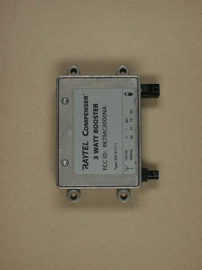
Click to zoom
Application Details
- Equipment Class
- AMP - Amplifier
- Date of Grant
- Feb 03, 2004
- Application Purpose
- Original Equipment
- Date of Application
- Feb 03, 2004
- Equipment Note
- Compenser
- Frequency Range
- 1850.20000000 - 1909.80000000
- Company
- Molex Technologies GmbH
- Country
- Germany
Documents & Files
Document Text
Text extracted from the exhibit documents filed with the FCC. Open a document above to read the original.
Users Manual
TM 203 8000 0.01 Compenser™ Installation Manual 01049 ACC -2- TM RAYTEL LLC a Nevada Limited Liability Company 711 Eighth Avenue, Suite G San Diego, CA 92101, USA T: +1 619 234-5929 F: +1 619 234-5853 www.raytel-llc.com Sales, Service and Support Office: 8820 Kenamar Drive, Suite 506 San Diego, CA 92121, USA T: +1 858 566-2170 F: +1 858 566-2179 [email protected] [email protected] -3- Compenser™ Table of Contents Table of Contents Introduction ....................................................................................... 4 RF Radiation Exposure ...................................................................... 4 Parts List ............................................................................................ 5 Safety Precautions ............................................................................ 6 Functional Description...................................................................... 8 Principle of Operation.......................................................................... 8 Installation Guide .............................................................................. 9 Required Accessory Items and Tools.................................................. 9 Getting Started .................................................................................... 9 Selecting the Mounting Position ....................................................... 10 Preparations ...................................................................................... 11 Installation ......................................................................................... 12 Operating the COMPENSER™ ....................................................... 13 Declaration of Conformity .............................................................. 14 Support ............................................................................................ 14 Warranty .......................................................................................... 14 Changes ........................................................................................... 14 Drilling Template.............................................................................. 15 -4- Compenser™Introduction Welcome Thank you very much for purchasing the Compenser™ from RAYTEL LLC. The COMPENSER™ provides optimum transmission and reception in your vehicle when using an external vehicle antenna. Furthermore it improves the operation of your mobile phone in conjunction with the use of a hands-free device. Introduction This installation manual for the COMPENSER™ contains all necessary information required to install the COMPENSER™ into your car. The COMPENSER™ has been designed for easy installation, however Raytel recommends strongly to have the system installed by a professional installer. Raytel's Limited Warranty is void unless installed by a qualified professional installer. Please visit our website www.raytel-llc.com for a listing of Raytel's qualified professional installers near you. RF Radiation Exposure The external antenna used for this mobile transmitter must provide a separation distance of at least 20 cm from all persons and must not be co-located or operating in conjunction with any other antenna or transmitter. The maximum allowed output power is 3 Watt and the maximum gain of the antennas to be used is 0 dBi. -5- Compenser™Parts List Parts List The packing unit should include the following items: Compenser™ Cable for Connection to Hands-Free-Car Kit (5m/16.5ft.) Adapter for Connection to Antenna (10cm/4 in) Power Supply Cable (3 Wires with a Plug) 4 Fixing Screws • Installation Manual • Installation Report • Registration and Warranty Card • RAYTEL LLC Limited Warranty Policy Figure 1 ➀ ➁ ➂ ➃ ➄ -6- Compenser™Safety Precautions Safety Precautions Improper Installation: The installation of the COMPENSER™ requires special knowledge, abilities and tools. Improper installation may cause damage to the unit or to the vehicle! We therefore strongly recommend having the installation done by a professional installer. Personal Injury: Inappropriate places for the installation of the COMPENSER™ may cause personal injury in accidents or may disable the safety equipment of the vehicle! Note the directions in the chapter Installation! When removing coverings or dashboard parts, sharp tools may cause personal injuries or material damage. Use adequate tools and remove parts carefully. Don't nick, cut or pull existing car wiring harnesses. Damage to Insulation of Wires: Damaged insulation on any wire of the existing vehicle wiring or the wiring of the COMPENSER™ system may cause damage to the unit, damage to the electrical system of the vehicle, and may cause short circuiting and fire. All wires should not be pinched or nicked and should be properly fixed to avoid any tensile stress or possible damage by chafing! Damage by Polarity Reversal or Short-Circuit: Incorrectly connected wires may cause a polarity reversal or short-circuit. This will result in severe damage to the equipment. It is essential to disconnect the car battery before beginning the electrical installation of the COMPENSER™! THE RAYTEL LLC LIMITED WARRANTY IS VOID UNLESS THE COMPENSER™ IS INSTALLED BY A QUALIFIED PROFESSIONAL INSTALLER. -7- Compenser™Safety Precautions Damage of Car Components: Drilling holes or using self-tapping screws when mounting the COMPENSER™ may cause damage to important vehicle components or to the wiring. Make sure there is enough space left behind drilling holes and screws! Effects on the Car's Electrical System: Although the COMPENSER™ has been designed for minimum radiation levels, improper installation of components of the system may influence the electronic equipment of the vehicle. Please note the instructions in the vehicle's owner's manual! Damage Caused by Wrong Replacement Parts or Accessories: Please visit Raytel's website www.raytel-llc.com for further information on replacement and accessory p…
Text truncated - open the document above for the full version.
Users Manual
TM 203 8000 0.02_GB Compenser™ Installation Manual 01049 ACC -2- TM RAYTEL LLC a Nevada Limited Liability Company 711 Eighth Avenue, Suite G San Diego, CA 92101, USA T: +1 619 234-5929 F: +1 619 234-5853 www.tellphone.com Sales, Service and Support Office: 8820 Kenamar Drive, Suite 506 San Diego, CA 92121, USA T: +1 858 566-2170 F: +1 858 566-2179 [email protected] [email protected] -3- Compenser™ Table of Contents Table of Contents Introduction ...................................................................................... 4 RF Radiation Exposure .................................................................... 4 Parts List ........................................................................................... 5 Safety Precautions ........................................................................... 6 Functional Description ..................................................................... 8 Principle of operation ......................................................................... 8 Installation Guide ............................................................................. 9 Required Accessory Items and Tools ................................................. 9 Getting Started ................................................................................... 9 Selecting the Mounting Position ...................................................... 10 Preparations ..................................................................................... 11 Installation ........................................................................................ 12 Operating the COMPENSER™ ...................................................... 13 Declaration of Conformity ............................................................. 14 Support ........................................................................................... 14 Warranty ......................................................................................... 14 Changes .......................................................................................... 14 Drilling Template ............................................................................ 15 -4- Compenser™Introduction Welcome Thank you very much for purchasing the COMPENSER™ from RAYTEL LLC. The COMPENSER™ provides optimum transmission and reception in your vehicle when using an external vehicle antenna. Furthermore it improves the operation of your mobile phone in conjunction with the use of a hands-free device. Introduction This installation manual for the COMPENSER™ contains all necessary information required to install the COMPENSER™ into your car. The COMPENSER™ has been designed for easy installation, however RAYTEL LLC recommends strongly to have the system installed by a professional installer. RAYTEL LLC Limited Warranty is void unless installed by a qualified professional installer. Please visit our website www.tellphone.com for a listing of RAYTEL LLC qualified professional installers near you. RF Radiation Exposure The external antenna used for this mobile transmitter must provide a separation distance of at least 20 cm from all persons and must not be co-located or operating in conjunction with any other antenna or transmitter. The maximum allowed gain of the antennas to be used is 0 dBi.
Users Manual
-5- Compenser™Parts List Parts List The packing unit should include the following items: Compenser™ Cable for Connection to Hands-Free-Car Kit (5m/16.5ft.) Adapter for Connection to Antenna (10cm/4 in) Power Supply Cable (3 Wires with a Plug) 4 Fixing Screws • Installation Manual • Installation Report • Registration and Warranty Card • RAYTEL LLC Limited Warranty Policy Figure 1 ➀ ➁ ➂ ➃ ➄ -6- Compenser™Safety Precautions Safety Precautions Improper Installation: The installation of the COMPENSER™ requires special knowledge, abilities and tools. Improper installation may cause damage to the unit or to the vehicle! We therefore strongly recommend having the installation done by a professional installer. Personal Injury: Inappropriate places for the installation of the COMPENSER™ may cause personal injury in accidents or may disable the safety equipment of the vehicle! Note the directions in the chapter Installation! When removing coverings or dashboard parts, sharp tools may cause personal injuries or material damage. Use adequate tools and remove parts carefully. Don't nick, cut or pull existing car wiring harnesses. Damage to Insulation of Wires: Damaged insulation on any wire of the existing vehicle wiring or the wiring of the COMPENSER™ system may cause damage to the unit, damage to the electrical system of the vehicle, and may cause short circuiting and fire. All wires should not be pinched or nicked and should be properly fixed to avoid any tensile stress or possible damage by chafing! Damage by Polarity Reversal or Short-Circuit: Incorrectly connected wires may cause a polarity reversal or short-circuit. This will result in severe damage to the equipment. It is essential to disconnect the car battery before beginning the electrical installation of the COMPENSER™! THE RAYTEL LLC LIMITED WARRANTY IS VOID UNLESS THE COMPENSER™ IS INSTALLED BY A QUALIFIED PROFESSIONAL INSTALLER. -7- Compenser™Safety Precautions Damage of Car Components: Drilling holes or using self-tapping screws when mounting the COMPENSER™ may cause damage to important vehicle components or to the wiring. Make sure there is enough space left behind drilling holes and screws! Effects on the Car's Electrical System: Although the COMPENSER™ has been designed for minimum radiation levels, improper installation of components of the system may influence the electronic equipment of the vehicle. Please note the instructions in the vehicle's owner's manual! Damage Caused by Wrong Replacement Parts or Accessories: Please visit RAYTEL LLC website www.tellphone.com for further information on replacement and accessory parts! Proper Use: The COMPENSER™ is to be used in cars only with a mobile phone that works in the GSM850 / GSM1900 MHz bands. Never spill liquid of any kind on this product. Do not disassemble this product. Take it to a qualified service center when service is required. -8- Compenser™Functional Description Functional Description The COMPENSER™ is a bi-directional transmitting and receiving booster which compensates for all cable and plug losses which occur in the signal path between the mobile phone and the external antenna. This provides optimum call quality through optimized transmitting and receiving characteristics. The COMPENSER™ is ready for operation when the vehicle's ignition is turned on. When there is no telephone call in progress, only the two receiving amplifiers are active. During a telephone call the two transmitting amplifiers are also active. The COMPENSER™ continues to be operational for approx. 2 hours after turning off the ignition. Only after the end of this time the COMPENSER™ switches off completely (standby); this allows continued use during short stops. In the standby mode the power consumption is minimal (< 0.1 mA), thereby sparing the car battery. When the ignition is turned on again, the COMPENSER™ is active again. The timer function can be put out of operation by wiring the ignition connection to the permanent plus (fig. 3, terminal 30, +). The COMPENSER™ is always on then (CAUTION! This means constant power consumption and use of the car battery!) Principle of operation Figure 2 -9- Compenser™Installation Guide Installation Guide The following installation instructions are not meant to be a guide for self installation, rather than a supporting document for the professional installer. Should you decide to install the COMPENSER™ yourself, which will void the RAYTEL LLC Limited Warranty, please read and follow the installation instructions very carefully and strictly observe all safety precautions. Required Accessory Items and Tools To perform the actual installation, the following tools are required: ~ Philips Screwdriver PH 1 ~ Universal Pliers ~ Side-Cutting Pliers ~ Variable Speed Hand Drill ~ 3.2 mm Drill Bit (Metal) ~ 9 mm Wrench ~ Multimeter or Test Lamp ~ Vehicle Specific Tools for Removing Coverings ~ Wire Straps ~ 3 cable connector clamps Getting Started Before you start with the installation of the COMPENSER™ make sure that all parts as listed in the Parts List are present. In order to fully operate the COMPENSER™ you will need the following additional parts and accessories, which are available through RAYTEL LLC authorized distributors and dealers: • Mobile Phone Antenna: An external mobile phone antenna is required for operating the COMPENSER™. Improper Installation: The installation of the COMPENSER™ requires special knowledge, abilities and tools. Improper installation may cause damage to the unit or to the vehicle! We therefore strongly recommend having the installation done by a professional installer. -10- Compenser™Installation Guide RAYTEL LLC recommends the use of its Mobile Phone Antenna which will fit to the antenna cable adapter of the COMPENSER™. Should you decide to use an existing mobile phone antenna of another brand, you may have to use an Antenna Adapter. After having checked and made available all above mentioned required parts for the installation of the COM…
Text truncated - open the document above for the full version.
Cover Letter(s)
Date: 01.12.2004 Federal Communications Commission Equipment Authorization Branch 7435 Oakland Mills Road Columbia, MD 21046 Request for Confidentiality Funkwerk Dabendorf GmbH FCC ID: RK7MC3000NA FCC Part 15 Certification Gentlemen, In accordance with 0.459 of CFR 47, Funkwerk Dabendorf GmbH hereby requests confidentiality of the Block diagram and Schematics attachments for the subject application. These documents contain detailed system and equipment description and related information about the product which Funkwerk Dabendorf GmbH considers to be proprietary, confidential and a custom design and otherwise would not release to the general public. Since the design is a basis from which future technological products will evolve, Funkwerk Dabendorf GmbH considers that this information would be of benefit to its competitors and that the disclosure of the information in these documents would give competitors an unfair advantage in the market. Sincerely, Signature Name Helmut Nast Title Dipl.-Ing. Company Funkwerk Dabendorf GmbH
Cover Letter(s)
ELECTRONIC TECHNOLOGY SYSTEMS DR.GENZ GMBH ELECTRONIC TECHNOLOGY SYSTEMS DR. GENZ GMBH - ETS - STORKOWER STRASSE 38c, D-15526 REICHENWALDE B. BERLIN Tel: 033631 888 000 FAX: 033631 888660 BZT ETS CERTIFICATION GMBH Mr. DIETER GRIEP; Mr. ANDREAS HERRMANN Storkower Str. 38c 15526 Reichenwalde b. Berlin GERMANY IHR ZEICHEN / YOUR REF. IHR SCHREIBEN / YOUR INFORM. UNSER ZEICHEN / OUR REF. DATUM / DATE 2004-02-04 Subject: Application for TCB Certification Applicant: Funkwerk Dabendorf GmbH Equipment: RAYTEL Compenser FCC ID: RK7MC3000NA Dear Sirs, Submitted herewith, on behalf of Funkwerk Dabendorf GmbH, is an application for certification under FCC Rule 22 and 24 of the following equipment: RAYTEL Compenser Attached are the 731Form, Confidentiality request letter, test report (TestRpt1=test data, TestRpt2=test plots), FCC ID label and label location information, test setup photographs, internal and external photographs, operational description, part’s list, block diagrams, schematics, tune procedure information and user manual. In accordance with 0.459 of CFR 47 Funkwerk Dabendorf GmbH hereby requests confidentiality of all Block Diagrams and Circuit Diagrams (Schematics), (see attached Confidentiality Request Letter) for the subject application. Should you have any questions or comments concerning the above, please contact the following e-mail addresses: [email protected] Electronic Technology Systems Dr. Genz GmbH Storkower Strasse 38c 15526 Reichenwalde bei Berlin Germany e-mail: [email protected] Best Regards Axel Müller ___________________________________________________________________________________ ETS Handelsregister: Bankverbindung: Electronic Technology Systems Dr. Genz GmbH Amtsgericht Frankfurt/Oder HRB 5151 Sparkasse Oder-Spree Storkower Strasse 38c Geschäftsführung: Dr. Dietmar Genz BLZ 170 550 50 D-15526 Reichenwalde b. Berlin Norbert Kaspar Kto. Nr. 3105165974
Cover Letter(s)
Date: 06.24.2004 Federal Communications Commission Equipment Authorization Branch 7435 Oakland Mills Road Columbia, MD 21046 Request for Confidentiality Funkwerk Dabendorf GmbH FCC ID: RK7MC3000NA FCC Part 15 Certification Gentlemen, In accordance with 0.459 of CFR 47, Funkwerk Dabendorf GmbH hereby requests confidentiality of the Block Diagram, Schematics, Part list, Operational Description and Antenna Specification for the subject application. These documents contain detailed system and equipment description and related information about the product which Funkwerk Dabendorf GmbH considers to be proprietary, confidential and a custom design and otherwise would not release to the general public. Since the design is a basis from which future technological products will evolve, Funkwerk Dabendorf GmbH considers that this information would be of benefit to its competitors and that the disclosure of the information in these documents would give competitors an unfair advantage in the market. Sincerely, Signature Name Helmut Nast Title Dipl.-Ing. Company Funkwerk Dabendorf GmbH
External Photos
ELECTRONIC TECHNOLOGY SYSTEMS DR.GENZ GMBH ETS Dr. Genz GmbH, GermanyRegistration number: G0M20312-8390-P2224Page 1 of 7 Appendix A. Pictures ELECTRONIC TECHNOLOGY SYSTEMS DR.GENZ GMBH ETS Dr. Genz GmbH, GermanyRegistration number: G0M20312-8390-P2224Page 2 of 7 ELECTRONIC TECHNOLOGY SYSTEMS DR.GENZ GMBH ETS Dr. Genz GmbH, GermanyRegistration number: G0M20312-8390-P2224Page 3 of 7
Internal Photos
ELECTRONIC TECHNOLOGY SYSTEMS DR.GENZ GMBH ETS Dr. Genz GmbH, GermanyRegistration number: G0M20312-8390-P2224Page 4 of 7 ELECTRONIC TECHNOLOGY SYSTEMS DR.GENZ GMBH ETS Dr. Genz GmbH, GermanyRegistration number: G0M20312-8390-P2224Page 5 of 7
Parts List/Tune Up Info
Date: 04.19.2004 Federal Communications Commission Equipment Authorization Branch 7435 Oakland Mills Road Columbia, MD 21046 Tune up information Funkwerk Dabendorf GmbH FCC ID: RK7MC3000NA FCC Part 15 Certification Gentlemen, the RAYTEL Compenser is an amplifier only and therefore there is no tuning procedure necessary. Sincerely, Signature Name Helmut Nast Title Dipl.-Ing. Company Funkwerk Dabendorf GmbH
RF Exposure Info
Federal Communications Commission Authorization and Evaluation Division Equipment Authorization Branch 7435 Oakland Mills Road Columbia, MD 21046 Applicant’s declaration concerning RF Radiation Exposure The RAYTEL Compenser (Type: 203 0111 1) is designed to be used as mobile transceiver. The external antenna used for this mobile transmitter must provide a separation distance of at least 20 cm from all persons and must not be co-located or operating in conjunction with any other antenna or transmitter. A safety statement concerning minimum separation distance will be integrated in the user’s manual to provide end-users with transmitter operating conditions for satisfying RF exposure compliance. RF Human Exposure Analysis as per 47CFR § 1.1310 For transmitter operating in the 824 – 890 MHz range, paragraph 1.1310 Table 1 limits maximum permissible exposure (MPE) to f / 1500 mW/cm² for uncontrolled environments and f / 300 mW/cm² for controlled environments. For transmitter operating in the 1850 – 1990 MHz range, paragraph 1.1310 Table 1 limits maximum permissible exposure (MPE) to 1.0 mW/cm² for uncontrolled environments and 5.0 mW/cm² for controlled environments. The far field on-axis power flux density (W / cm²) is calculated using the following formula: S = G * P T / (4 * pi * R²) Calculations: • Cellular Band 824-890 MHz - Limit 0.549 / 2.746 S = (1 * 2,377 + 10³) / (4 * 3.14 * 20²) = 0.473 mW/cm² < Limit • Cellular Band 1850-1990 MHz - Limit 1.0 / 5.0 S = (1 * 1.58 * 10³) / (4 * 3.14 * 20²) = 0.3144 mW/cm² < Limit The RAYTEL Compenser (Type: 203 0111 1) keeps the above mentioned limit. Place, date Dabendorf, 04.22.2004 Signature
Test Report
ELECTRONIC TECHNOLOGY SYSTEMS DR. GENZ GMBH TEST - REPORT FCC RULES PARTS 22 and 24 FCC ID: RK7MC3000NA Test report no.: G0M20312-8390-P-2224 FCC ELECTRONIC TECHNOLOGY SYSTEMSSTORKOWER STRASSE 38C, D-15526 REICHENWALDE B. BERLIN DR. GENZ GMBHPHONE +49-33631-888 00 FAX +49-33631-888 66 ETS Dr. Genz GmbH, GermanyRegistration number: G0M20312-8390-P-2224Page 1 of 41 ELECTRONIC TECHNOLOGY SYSTEMS DR.GENZ GMBH TABLE OF CONTENTS 1General information 1.1Notes 1.2Testing laboratory 1.3Details of approval holder 1.4Application details 1.5Test item 1.6Test standards 2Technical test 2.1Summary of test results 2.2Test environment 2.3Test equipment utilized 2.4General Test Procedure 3 Test Results 4 RF Power Output, FCC 2.1046 4.1 Test Procedure 4.2 Test Results 5 Radiated Power FCC 22.913, FCC 24.232 5.1 Test Procedure 5.2 Test Results 6 Modulation Deviation Limiting, FCC 2.1047, 22.915(b)(c) 6.1 Test Procedure 6.2 Test Results 7 Audio Filter Characteristics, FCC 22.915(d) 7.1 Test Procedure 7.2 Test Results 8 Emission Limitations, , FCC 2.1049 8.1 Test Procedure 8.2 Test Results 9 Occupied Bandwidth FCC 22.917(b)(d); FCC 2.1049 9.1 Test Procedure 9.2 Test Results 10 Emission in Receiver Critical Band FCC 22.917(f) 10.1Test Procedure 10.2Test results 11 Out of Band Emissions at Antenna Terminals , FCC 2.1051, FCC 22.917(e), FCC 22.917(f), 24.238(a) 11.1. Test Procedure 11.2. Test Results ETS Dr. Genz GmbH, GermanyRegistration number: G0M20312-8390-P-2224Page 2 of 41 ELECTRONIC TECHNOLOGY SYSTEMS DR.GENZ GMBH 12 Field Strength of Spurious Radiation, FCC 2.1053, 24.236 13.1 Test Procedure 12.2 Test Results 13 Line Conducted Emissions, FCC 15.207 13.1 Test Procedure 13.2 Test Results 14 Frequency Stability vs Temperature, FCC 2.1055, 22.355, 24.235 14.1 Test Procedure 14.2 Test Equipment 15 Frequency Stability vs Voltage, FCC 2.1055, 22.355, 24.235 15.1 Test Procedure 15.2 Test Equipment ETS Dr. Genz GmbH, GermanyRegistration number: G0M20312-8390-P-2224Page 3 of 41 ELECTRONIC TECHNOLOGY SYSTEMS DR.GENZ GMBH 1General Information 1.1Notes The purpose of conformity testing is to increase the probability of adherence to the essential requirements or conformity specifications, as appropriate. The complexity of the technical specifications, however, means that full and thorough testing is impractical for both technical and economic reasons. Furthermore, there is no guarantee that a test sample which has passed all the relevant tests conforms to a specification. Neither is there any guarantee that such a test sample will interwork with other genuinely open systems. The existence of the tests nevertheless provides the confidence that the test sample possesses the qualities as maintained and that is performance generally conforms to representative cases of communications equipment. The test results of this test report relate exclusively to the item tested as specified in 1.5. The test report may only be reproduced or published in full. Reproduction or publication of extracts from the report requires the prior written approval of the ELECTRONIC TECHNOLOGY SYSTEMS DR. GENZ GMBH. Tester: 27.01.2004N. Kaspar DateETS-Lab.NameSignature Technical responsibility for area of testing: 27.01.2004Dr. Genz DateETSNameSignature ETS Dr. Genz GmbH, GermanyRegistration number: G0M20312-8390-P-2224Page 4 of 41 ELECTRONIC TECHNOLOGY SYSTEMS DR.GENZ GMBH 1.2 Testing laboratory 1.2.1Location ELECTRONIC TECHNOLOGY SYSTEM DR. GENZ GMBH (ETS) Storkower Straße 38c D-15526 Reichenwalde b. Berlin Germany Telephone : +49 33631 888 00 Telefax: +49 33631 888 66 1.2.2Details of accreditation status A CCREDITED TESTING LABORATORY DAR-REGISTRATION NUMBER: TTI-P-G 126/96 ACCREDITED COMPETENT BODY DAR-REGISTRATION NUMBER: BPT-ZE-026/96 FCC FILED TEST LABORATORY REG. NO. 96970 BLUETOOTH QUALIFICATION TEST FACILITY (BQTF) ACCREDITED BY: BLUETOOTH QUALIFICATION REVIEW BOARD (BQRF) I NDUSTRY CANADA FILED TEST LABORATORY REG. NO. IC 3470 A2LA A CCREDITEDCertificate Number: 1983-01 1.3Details of approval holder Name: Funkwerk Dabendorf GmbH Street: Märkische Strasse Town: 15806 Dabendorf Country: Germany Telephone: 0049 3377 316-136 Fax: 0049 3377 316-134 Contact: Herr Helmut Nast E-Mail: [email protected] ETS Dr. Genz GmbH, GermanyRegistration number: G0M20312-8390-P-2224Page 5 of 41 ELECTRONIC TECHNOLOGY SYSTEMS DR.GENZ GMBH 1.4Application details Date of receipt of application: 11.12.2003 Date of receipt of test item: 11.12.2003 Date of test: 18.12.2003-30.12.2003 1.5Test item Description of test item: Compenser Type identification: MC3000 NA Serial number: Test model without serial number. Photos: See annex A. Technical data Frequency range Tx – GSM 850: 824.2 – 848.80 MHz Frequency range Tx – PCS: 1850.2 – 1909.8 MHz Frequency range Rx - GSM 850: 869.2 – 893.8 MHz Frequency range Rx - PCS: 1930.2 – 1989.8 MHz Antenna: Multi band roof mount antenna 810 – 2170 MHz Antenna type: Quarter-wave whip with 5 m antenna cable RG 58 Antenna Gain: 0 dBi Power supply : 12,0 V DC Operating mode: duplex Type of modulation: GMSK (GSM modulation) Emission: GXW Manufacturer: (if applicable) Name: Street: Town: Country: ETS Dr. Genz GmbH, GermanyRegistration number: G0M20312-8390-P-2224Page 6 of 41 ELECTRONIC TECHNOLOGY SYSTEMS DR.GENZ GMBH 1.6Test standards Technical standard: FCC Parts 22, 24, 2, 15 Additional information: Because of using the GSM 850 as an alternative technology in 850 MHz band, not all test cases of FCC Part 22 are required. The compensor MC 3000NA, the EUT, intended to use in a vehicular environment, is an bi-directional working amplifier only and do not generate the transmitting information and frequency itself. Therefore test cases like Frequency Stability versus temperature, Frequency Stability versus voltage and Line Conducted Emission tests were not applicable. For testing purposes a GSM handset SIEMENS Cingular was used in order to generate GSM typical uplink signals and a base station simulator for generating the downlink signa…
Text truncated - open the document above for the full version.
Test Setup Photos
ELECTRONIC TECHNOLOGY SYSTEMS DR.GENZ GMBH ETS Dr. Genz GmbH, GermanyRegistration number: G0M20312-8390-P2224Page 6 of 7 ELECTRONIC TECHNOLOGY SYSTEMS DR.GENZ GMBH ETS Dr. Genz GmbH, GermanyRegistration number: G0M20312-8390-P2224Page 7 of 7
Contact Information
Applicant
Ines Baufeld
Technical Contact
Funkwerk Dabendorf GmbHHelmut Nast
[email protected]0049 3377 316 136
Maerkische Strasse / Gewerbegebiet · Dabendorf · Germany
Non-Technical Contact
Funkwerk Dabendorf GmbHLutz Pfister
[email protected]0049 3377 316 102
Test Firm
Eurofins Product Service GmbHRobert Kschiwan-Kaspar
Technical Specifications
| # | Rule Parts | Frequency Range | Power Output | Emission | Tolerance |
|---|---|---|---|---|---|
| 2 | 24 | 1.85 GHz - 1.91 GHz | 1.58 W | 250KGXW | 1 ppm |
Other Applications from Molex Technologies GmbH
RK7WCH-302
Aug 04, 2020Vehicle Wireless Charging Unit with NFC
Equipment Class
DXX - Part 15 Low Power Communication Device Transmitter
RK7MBC-NAR2
Apr 05, 2020Wideband Consumer Signal Booster
Equipment Class
B2W - Part 20 Wideband Consumer Booster (CMRS)
RK7177-00
Jun 04, 2015On board vehicle Wireless Charging Unit
Equipment Class
DCD - Part 15 Low Power Transmitter Below 1705 kHz
RK7173-00
May 27, 2015On board vehicle Wireless Charging Unit
Equipment Class
DCD - Part 15 Low Power Transmitter Below 1705 kHz
RK7156-01
Jul 28, 2010Bluetooth Handsfree Car Kit
Equipment Class
DSS - Part 15 Spread Spectrum Transmitter