RMK-RECZIGB1Wireless Transmitter Base for Data Acquisition System
TMI USA INC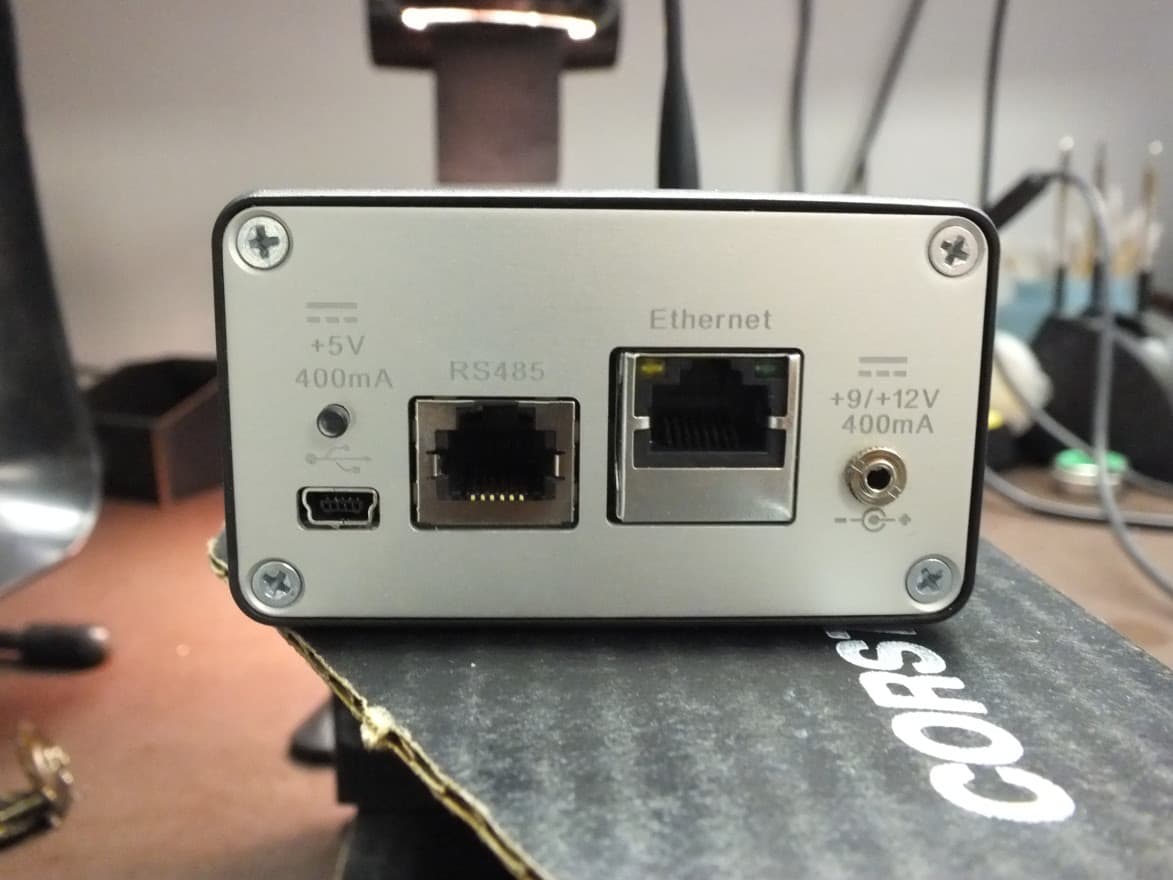
Click to zoom
Application Details
- Equipment Class
- DTS - Digital Transmission System
- Date of Grant
- Feb 07, 2013
- Application Purpose
- Original Equipment
- Date of Application
- Feb 06, 2013
- Equipment Note
- Wireless Transmitter Base for Data Acquisition System
- Frequency Range
- 2405.00000000 - 2475.00000000
- Company
- TMI USA INC
- Country
- United States
Documents & Files
Document Text
Text extracted from the exhibit documents filed with the FCC. Open a document above to read the original.
Users Manual
Rhein Tech Laboratories, Inc. Client: TMI-USA, Inc. 360 Herndon Parkway Model #: ZIGBEEBASE1 Suite 1400 Standards: FCC 15.247/IC RSS-210 Herndon, VA 20170 ID’s: RMK-RECZIGB1/10839A-RECZIGB1 http://www.rheintech.com Report #: 2013024 Page 42 of 50 Appendix K: Manual Please refer to the following pages. User’s guide Radio NanoVACQ 2.4 GHz TO/FORM/104701.ed1 TO/NL3/NVQ/DOC/NVQ_RADIO/EN.ed1 FCC page 1 / 10 Main specifications : - dimensions : D.31 x H.45 mm - volume : 34cc - weight : 120 g - m emory : 48 000 acquisitions ÷ number of channels TMI-ORION Parc de Bellegarde, Bât. C 1, chemin de Borie F-34170 CASTELNAU LE LEZ Tél. : + (33) 4.99.52.67.10 Fax : + (33) 4.99.52.67.19 USER’S GUIDE Radio NanoVACQ 2.4GHz [NVQ-2.4GHz] Quality control Radio Data logger User’s guide Radio NanoVACQ 2.4 GHz TO/FORM/104701.ed1 TO/NL3/NVQ/DOC/NVQ_RADIO/EN.ed1 FCC page 2 / 10 Main specifications : - dimensions : D.31 x H.45 mm - volume : 34cc - weight : 120 g - m emory : 48 000 acquisitions ÷ number of channels TMI-ORION Parc de Bellegarde, Bât. C 1, chemin de Borie F-34170 CASTELNAU LE LEZ Tél. : + (33) 4.99.52.67.10 Fax : + (33) 4.99.52.67.19 USER’S GUIDE Radio NanoVACQ 2.4GHz [NVQ-2.4GHz] Table of contents 1. General description of the Radio NanoVacq 2.4 GHz ________________ 3 2. Precautions of use ___________________________________________ 4 3. Disconnecting device _________________________________________ 4 4. Electrical Safety Data Sheet ___________________________________ 5 5. NanoVACQ Radio 2.4 GHz ____________________________________ 5 6. Radio Receiver 2.4 GHz - ZigBeeBase ___________________________ 5 7. Detailed description of the Radio NanoVACQ 2.4 GHz ______________ 6 8. General ___________________________________________________ 6 9. Mechanical resistance ________________________________________ 6 10. Antenna ___________________________________________________ 7 11. Caution about the NanoVACQ temperature _______________________ 7 12. Use the Radio Receiver 2.4 GHz ________________________________ 8 13. USB port connexion _________________________________________ 8 14. Long distance communication via RS485 _________________________ 9 15. Communication by Ethernet port _______________________________ 9 All the pictures shown in this guide are not contractual. User’s guide Radio NanoVACQ 2.4 GHz TO/FORM/104701.ed1 TO/NL3/NVQ/DOC/NVQ_RADIO/EN.ed1 FCC page 3 / 10 Main specifications : - dimensions : D.31 x H.45 mm - volume : 34cc - weight : 120 g - m emory : 48 000 acquisitions ÷ number of channels TMI-ORION Parc de Bellegarde, Bât. C 1, chemin de Borie F-34170 CASTELNAU LE LEZ Tél. : + (33) 4.99.52.67.10 Fax : + (33) 4.99.52.67.19 USER’S GUIDE Radio NanoVACQ 2.4GHz [NVQ-2.4GHz] 1. General description of the Radio NanoVacq 2.4 GHz The Radio NanoVACQ 2.4 GHz is a wireless data logger equipped with one or multiple sensors. The design features the following: the ability to transmit data, thanks to the radio communication, (temperature, pressure, humidity,..) in real time and beside the ability to record data in side the memory. The used frequency band is located in the 2.4 GHz (industrial equipment) ISM band (scientific or medical). The Radio NanoVACQ 2.4 GHz is designed to be exposed to temperatures ranging from -80 to +150°C and is fully waterproof to immersion; it may be exposed to some pressure up to 15 bars. The logger body is made of 316L stainless steel. The Radio NanoVACQ 2.4 GHz body is 31 mm diameter. Its height may vary from 45 to 135 mm according to the temperature range and the battery pack used. The Radio NanoVACQ 2.4 GHz antenna, that can be unplugged from the base, is 50 mm long and is insulated. It allows wireless data transmission. The User would use the Software Qlever to set the parameters of the NanoVACQ 2.4GHz. When programming, the user would select the desired operating mode: - Transmitting data without recording inside the memory, - Recording data without transmitting, - Both transmitting data by radio & recording inside the memory. The Radio NanoVACQ 2.4 GHz is wireless because it has its own battery pack specially designed for this purpose and easily replaceable (only batteries provided by TMI-Orion can be used). User’s guide Radio NanoVACQ 2.4 GHz TO/FORM/104701.ed1 TO/NL3/NVQ/DOC/NVQ_RADIO/EN.ed1 FCC page 4 / 10 Main specifications : - dimensions : D.31 x H.45 mm - volume : 34cc - weight : 120 g - m emory : 48 000 acquisitions ÷ number of channels TMI-ORION Parc de Bellegarde, Bât. C 1, chemin de Borie F-34170 CASTELNAU LE LEZ Tél. : + (33) 4.99.52.67.10 Fax : + (33) 4.99.52.67.19 USER’S GUIDE Radio NanoVACQ 2.4GHz [NVQ-2.4GHz] The Radio NanoVACQ 2.4 GHz system generally includes: - The Radio NanoVACQ 2.4 GHz with a new battery pack and its transmitting antenna, - An interface for PC communication, - A radio receiver and its antenna, - An operating software, - An opening wrench, - The NanoVACQ calibration file, - A calibration certificate, - A transport case (optional). RS485 option : - RS232 to RS485 converter cable with RJ11 card, - 110V/220V adapter for radio receiver (RS485 or Ethernet only). 2. Precautions of use The Radio NanoVACQ 2.4 GHz and the Radio Receiver 2.4 GHz are specific materials that should be used in a restricted access area only, with users who have carrefully read every precautions of use written in the manuals. Changes or modifications not expressly approved by the manufacturer could void the user’s authority to operate the equipment. This device complies with Industry Canada licence-exempt RSS standard(s). Operation is subject to the following two conditions: (1) this device may not cause interference, and (2) this device must accept any interference, including interference that may cause undesired operation of the device. Le présent appareil est conforme aux CNR d'Industrie Canada applicables aux appareils radio exempts de licence. L'exploitation est autorisée aux deux conditions suivantes : (1) l'appareil ne doit pas produire de brouillage, et (2) l…
Text truncated - open the document above for the full version.
Attestation Statements
11491 Sunset Hills Road Suite 310 T~ ITMI-USA INC. Reston, VA 20190 www.tmigi.com (703) 668-0114 Fax: (703) 668-0118 January zs" 2013, To whom it may concern Bec ause of an upper band edge fail ure when using channel 26 (2480 MHz) as the hig hest channel of operat ion, this channel will be dis abled and the highest channel of operation will be channel 25 (2475 MHz). Guillau me Fav re V.P. of Operat ions
Attestation Statements
11491 Sunset Hills Road Suite 310 TMI-USA INC. Reston , VA 20190 T ~ I www.tmigi.com (703) 668-0114 Fax: (703) 668-0118 ATTESTATION lETTER Reston 02/08/2013 The statement in the user manual regarding restricted access stems from a European certification requirement concerning electrical safety. This statement does not apply in any way to the transmitter. Guillaume Favre V.P. of Operations
Cover Letter(s)
Rhein Tech Laboratories, Inc. Client: TMI-USA, Inc. 360 Herndon Parkway Model #: ZIGBEEBASE1 Suite 1400 Standards: FCC 15.247/IC RSS-210 Herndon, VA 20170 ID’s: RMK-RECZIGB1/10839A-RECZIGB1 http://www.rheintech.com Report #: 2013024 Page 33 of 50 Appendix B: Agency Authorization Letter Please refer to the following page.
Cover Letter(s)
Rhein Tech Laboratories, Inc. Client: TMI-USA, Inc. 360 Herndon Parkway Model #: ZIGBEEBASE1 Suite 1400 Standards: FCC 15.247/IC RSS-210 Herndon, VA 20170 ID’s: RMK-RECZIGB1/10839A-RECZIGB1 http://www.rheintech.com Report #: 2013024 Page 34 of 50 Appendix C: FCC Confidentiality Request Letter Please refer to the following page.
External Photos
Rhein Tech Laboratories, Inc. Client: TMI-USA, Inc. 360 Herndon Parkway Model #: ZIGBEEBASE1 Suite 1400 Standards: FCC 15.247/IC RSS-210 Herndon, VA 20170 ID’s: RMK-RECZIGB1/10839A-RECZIGB1 http://www.rheintech.com Report #: 2013024 Page 49 of 50 Appendix M: External Photographs Please refer to the following pages. RADIO RECEIVER 2.4 GHZ – ZIGBEEBASE Figure 1: Radio Receiver Top View Figure 2: Radio Receiver Side View Figure 3: Radio Receiver Front View Figure 4: Radio Receiver Rear View Figure 5: Radio Receiver Side View Figure 6: Radio Receiver Bottom View
ID Label/Location Info
Rhein Tech Laboratories, Inc. Client: TMI-USA, Inc. 360 Herndon Parkway Model #: ZIGBEEBASE1 Suite 1400 Standards: FCC 15.247/IC RSS-210 Herndon, VA 20170 ID’s: RMK-RECZIGB1/10839A-RECZIGB1 http://www.rheintech.com Report #: 2013024 Page 38 of 50 Appendix G: ID Label and Label Location Please refer to the following page. ID Label Sample This device complies with Part 15 of the FCC Rules. Operation is subject to the following two conditions: 1. this device may not cause harmful interference, and 2. this device must accept any interference received, including interference that may cause undesired operation. FCC ID: RMK-RECZIGB1 IC: 10839A-RECZIGB1 Model: ZIGBEEBASE1 ID Label Location ID Label Location
Internal Photos
Rhein Tech Laboratories, Inc. Client: TMI-USA, Inc. 360 Herndon Parkway Model #: ZIGBEEBASE1 Suite 1400 Standards: FCC 15.247/IC RSS-210 Herndon, VA 20170 ID’s: RMK-RECZIGB1/10839A-RECZIGB1 http://www.rheintech.com Report #: 2013024 Page 50 of 50 Appendix N: Internal Photographs Please refer to the following pages. Figure 1: Receiver PCB Top View Figure 2: Receiver PCB Side View Figure 3: Receiver PCB Side View Figure 4: Receiver PCB Bottom View
RF Exposure Info
Rhein Tech Laboratories, Inc. Client: TMI-USA, Inc. 360 Herndon Parkway Model #: ZIGBEEBASE1 Suite 1400 Standards: FCC 15.247/IC RSS-210 Herndon, VA 20170 ID’s: RMK-RECZIGB1/10839A-RECZIGB1 http://www.rheintech.com Report #: 2013024 Page 32 of 50 Appendix A: FCC Part 1.1307, 1.1310, 2.1091, 2.1093; IC RSS-Gen: RF Exposure No RF Exposure Evaluation Required if power is below the following threshold: Tunable Range f(GHz) Low f(GHz) High Center of Tunable Band (GHz) 60/f SAR Limitation (mW) 2.405 2.475 2.440 24.8 Maximum measured transmitter power: Pout Conducted (mW) Maximum Antenna Gain (numeric) Pout EIRP (mW) 2.6 2.95 7.7 Threshold at which no RF exposure evaluation is 24.6 mW. Maximum TX Power is 2.6 mW conducted and 7.7 mW EIRP. Conclusion: No RF exposure evaluation is required since the maximum Transmitter Pout (both conducted and EIRP) is well below the FCC threshold.
Test Setup Photos
Rhein Tech Laboratories, Inc. Client: TMI-USA, Inc. 360 Herndon Parkway Model #: ZIGBEEBASE1 Suite 1400 Standards: FCC 15.247/IC RSS-210 Herndon, VA 20170 ID’s: RMK-RECZIGB1/10839A-RECZIGB1 http://www.rheintech.com Report #: 2013024 Page 43 of 50 Appendix L: Test Photographs Photograph 1: Radiated Testing – Front View Rhein Tech Laboratories, Inc. Client: TMI-USA, Inc. 360 Herndon Parkway Model #: ZIGBEEBASE1 Suite 1400 Standards: FCC 15.247/IC RSS-210 Herndon, VA 20170 ID’s: RMK-RECZIGB1/10839A-RECZIGB1 http://www.rheintech.com Report #: 2013024 Page 44 of 50 Photograph 2: Radiated Testing – Rear View Rhein Tech Laboratories, Inc. Client: TMI-USA, Inc. 360 Herndon Parkway Model #: ZIGBEEBASE1 Suite 1400 Standards: FCC 15.247/IC RSS-210 Herndon, VA 20170 ID’s: RMK-RECZIGB1/10839A-RECZIGB1 http://www.rheintech.com Report #: 2013024 Page 45 of 50 Photograph 3: AC Conducted Testing – Front View – USB Powered Rhein Tech Laboratories, Inc. Client: TMI-USA, Inc. 360 Herndon Parkway Model #: ZIGBEEBASE1 Suite 1400 Standards: FCC 15.247/IC RSS-210 Herndon, VA 20170 ID’s: RMK-RECZIGB1/10839A-RECZIGB1 http://www.rheintech.com Report #: 2013024 Page 46 of 50 Photograph 4: AC Conducted Testing – Rear View – USB Powered Rhein Tech Laboratories, Inc. Client: TMI-USA, Inc. 360 Herndon Parkway Model #: ZIGBEEBASE1 Suite 1400 Standards: FCC 15.247/IC RSS-210 Herndon, VA 20170 ID’s: RMK-RECZIGB1/10839A-RECZIGB1 http://www.rheintech.com Report #: 2013024 Page 47 of 50 Photograph 5: AC Conducted Testing – Front View – AC Adapter Rhein Tech Laboratories, Inc. Client: TMI-USA, Inc. 360 Herndon Parkway Model #: ZIGBEEBASE1 Suite 1400 Standards: FCC 15.247/IC RSS-210 Herndon, VA 20170 ID’s: RMK-RECZIGB1/10839A-RECZIGB1 http://www.rheintech.com Report #: 2013024 Page 48 of 50 Photograph 6: AC Conducted Testing – Rear View – AC Adapter
Contact Information
Applicant
Guillaume Favre
Technical Contact
Rhein Tech LabsRick McMurray
[email protected]7036890368
360 Herndon Parkway · Herndon · United States
Test Firm
Rhein Tech Laboratories, Inc.Richard McMurray
Technical Specifications
| # | Rule Parts | Frequency Range | Power Output |
|---|---|---|---|
| 1 | 15C | 2.40 GHz - 2.48 GHz | 2.60 mW |
Other Applications from TMI USA INC
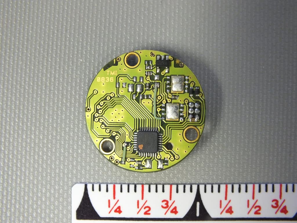
RMK-ZIGB1
Mar 25, 2013Wireless Module for Data Acquisition System
Equipment Class
DTS - Digital Transmission System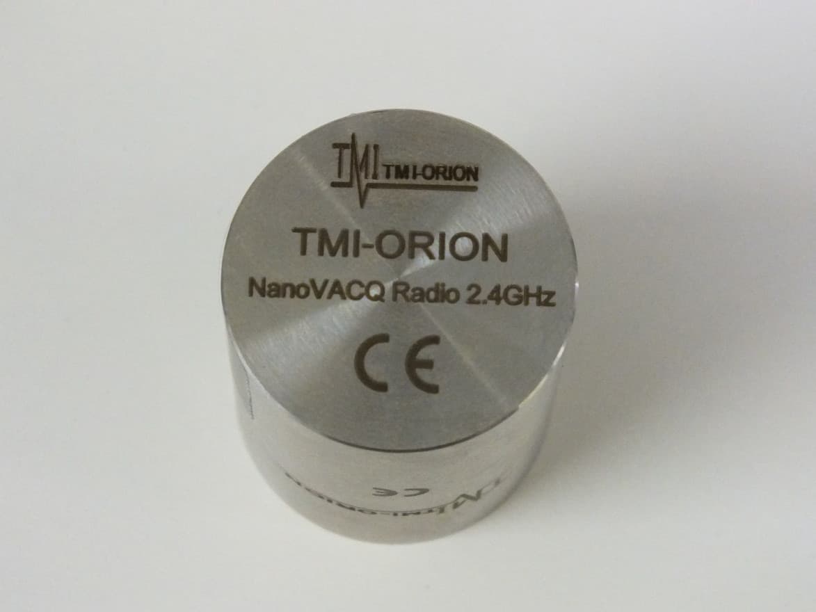
RMK-NVQZIGB1
Feb 05, 2013Wireless Data Acquisition System
Equipment Class
DTS - Digital Transmission System