RMK-ZIGB1Wireless Module for Data Acquisition System
TMI USA INC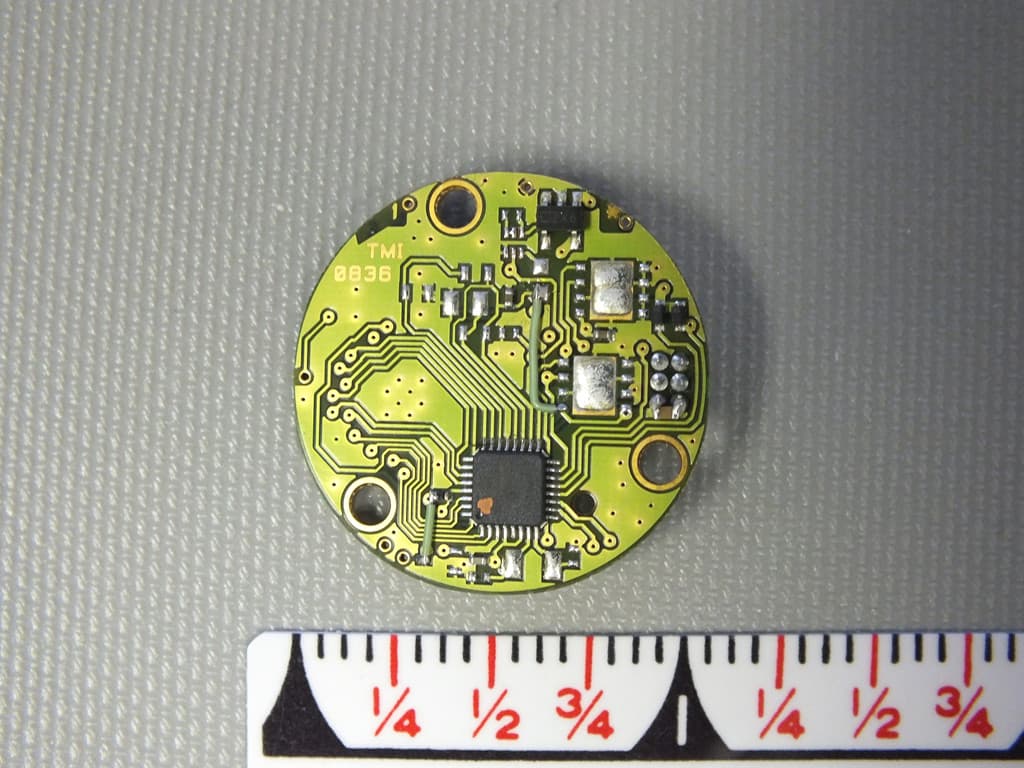
Click to zoom
Application Details
- Equipment Class
- DTS - Digital Transmission System
- Date of Grant
- Mar 25, 2013
- Application Purpose
- Original Equipment
- Date of Application
- Mar 24, 2013
- Equipment Note
- Wireless Module for Data Acquisition System
- Frequency Range
- 2405.00000000 - 2480.00000000
- Company
- TMI USA INC
- Country
- United States
Documents & Files
Document Text
Text extracted from the exhibit documents filed with the FCC. Open a document above to read the original.
Users Manual
Rhein Tech Laboratories, Inc. Client: TMI-USA, Inc. 360 Herndon Parkway Model: RADIOZIGB1 Suite 1400 Standards: FCC 15.247/IC RSS-210 Herndon, VA 20170 ID’s: RMK-ZIGB1/10839A-ZIGB1 http://www.rheintech.com Report #: 2013031 Page 45 of 52 Appendix M: Manual Please refer to the following pages. ZigBeeLog Module – User’s guide TO0903_022_DOC_1.00_ZigBeeLog_User's guide ZigBeeLog Module page 1 / 4 USER’S GUIDE ZigBeeLog Module TMI-ORION Parc de Bellegarde, Bât. C 1 chemin de Borie 34170 CASTELNAU-LE-LEZ – FRANCE Tél. : + (33) 4.99.52.67.10 Fax: + (33) 4.99.52.67.19 TO/FORM/104701.ed1 Quality Control Sample Host Data loggers ZigBeeLog Module – User’s guide TO0903_022_DOC_1.00_ZigBeeLog_User's guide ZigBeeLog Module page 2 / 4 USER’S GUIDE ZigBeeLog Module TMI-ORION Parc de Bellegarde, Bât. C 1 chemin de Borie 34170 CASTELNAU-LE-LEZ – FRANCE Tél. : + (33) 4.99.52.67.10 Fax: + (33) 4.99.52.67.19 TO/FORM/104701.ed1 Table of contents 1 – Description of the ZigBeeLog module ________________________ 3 2 – Use of the ZigBeeLog module ________________________________ 3 ZigBeeLog Module – User’s guide TO0903_022_DOC_1.00_ZigBeeLog_User's guide ZigBeeLog Module page 3 / 4 USER’S GUIDE ZigBeeLog Module TMI-ORION Parc de Bellegarde, Bât. C 1 chemin de Borie 34170 CASTELNAU-LE-LEZ – FRANCE Tél. : + (33) 4.99.52.67.10 Fax: + (33) 4.99.52.67.19 TO/FORM/104701.ed1 1 – Description of the ZigBeeLog module The ZigBeeLog electronic board module (RMK-ZIGB1 / 10839A-ZIGB1) contains all the electronics components for RF transmissions and power regulators. TMI is the designer of the ZigBeeLog module intended for use in data loggers made by TMI only. The ZigBeeLog module contains its proper power supply regulation through a LDO regulator. This LDO powers the RF component with constant voltage. The power is supplied by a battery pack made by TMI (10Vdc Max). The ZigBeeLog module is assembled in a stainless steel enclosure to constitute radio data loggers. In the stainless steel enclosure, the ZigBeeLog module is permanently connected to a coaxial cable and then to a RF connector. In this manner, the only access the user has is to the RF connector to connect a specific antenna provided by TMI. The antennas used with the ZigBeeLog module are Omni-directional and the gain is less than 2.2dBi. 2 – Use of the ZigBeeLog module The ZigBeeLog module was specifically developed by TMI for use in TMI’s radio data loggers only. Every host data logger shall contain the label Where FCC ID: RMK-ZIGB1 / IC: 10839A-ZIGB1 is the module’s certification number This device complies with Part 15 of the FCC Rules. Operation is subject to the following two conditions: 1. this device may not cause harmful interference, and 2. this device must accept any interference received, including interference that may cause undesired operation. Contains FCC ID: RMK-ZIGB1 IC: 10839A-ZIGB1 Model: RADIOZIGB1 ZigBeeLog Module – User’s guide TO0903_022_DOC_1.00_ZigBeeLog_User's guide ZigBeeLog Module page 4 / 4 USER’S GUIDE ZigBeeLog Module TMI-ORION Parc de Bellegarde, Bât. C 1 chemin de Borie 34170 CASTELNAU-LE-LEZ – FRANCE Tél. : + (33) 4.99.52.67.10 Fax: + (33) 4.99.52.67.19 TO/FORM/104701.ed1 Changes or modifications not expressly approved by the manufacturer could void the user’s authority to operate the equipment. This device complies with Industry Canada license-exempt RSS standard(s). Operation is subject to the following two conditions: (1) This device may not cause interference, and (2) this device must accept any interference, including interference that may cause undesired operation of the device. Le présent appareil est conforme aux CNR d'Industrie Canada applicables aux appareils radio exempts de licence. L'exploitation est autorisée aux deux conditions suivantes : (1) l'appareil ne doit pas produire de brouillage, et (2) l'utilisateur de l'appareil doit accepter tout brouillage radioélectrique subi, même si le brouillage est susceptible d'en compromettre le fonctionnement. Not following those precautions and instructions would lead to irreversible damages of the module. No repair would be guaranteed by TMI-ORION.
Cover Letter(s)
Rhein Tech Laboratories, Inc. Client: TMI-USA, Inc. 360 Herndon Parkway Model: RADIOZIGB1 Suite 1400 Standards: FCC 15.247/IC RSS-210 Herndon, VA 20170 ID’s: RMK-ZIGB1/10839A-ZIGB1 http://www.rheintech.com Report #: 2013031 Page 34 of 52 Appendix B: Agency Authorization Letter Please refer to the following page.
Cover Letter(s)
Rhein Tech Laboratories, Inc. Client: TMI-USA, Inc. 360 Herndon Parkway Model: RADIOZIGB1 Suite 1400 Standards: FCC 15.247/IC RSS-210 Herndon, VA 20170 ID’s: RMK-ZIGB1/10839A-ZIGB1 http://www.rheintech.com Report #: 2013031 Page 35 of 52 Appendix C: FCC Confidentiality Request Letter Please refer to the following page.
Cover Letter(s)
Rhein Tech Laboratories, Inc. Client: TMI-USA, Inc. 360 Herndon Parkway Model: RADIOZIGB1 Suite 1400 Standards: FCC 15.247/IC RSS-210 Herndon, VA 20170 ID’s: RMK-ZIGB1/10839A-ZIGB1 http://www.rheintech.com Report #: 2013031 Page 36 of 52 Appendix D: FCC Limited Modular Approval Please refer to the following pages.
External Photos
Rhein Tech Laboratories, Inc. Client: TMI-USA, Inc. 360 Herndon Parkway Model: RADIOZIGB1 Suite 1400 Standards: FCC 15.247/IC RSS-210 Herndon, VA 20170 ID’s: RMK-ZIGB1/10839A-ZIGB1 http://www.rheintech.com Report #: 2013031 Page 49 of 52 Appendix O: External Photographs Photograph 5: Top View Rhein Tech Laboratories, Inc. Client: TMI-USA, Inc. 360 Herndon Parkway Model: RADIOZIGB1 Suite 1400 Standards: FCC 15.247/IC RSS-210 Herndon, VA 20170 ID’s: RMK-ZIGB1/10839A-ZIGB1 http://www.rheintech.com Report #: 2013031 Page 50 of 52 Photograph 6: Bottom View
ID Label/Location Info
Rhein Tech Laboratories, Inc. Client: TMI-USA, Inc. 360 Herndon Parkway Model: RADIOZIGB1 Suite 1400 Standards: FCC 15.247/IC RSS-210 Herndon, VA 20170 ID’s: RMK-ZIGB1/10839A-ZIGB1 http://www.rheintech.com Report #: 2013031 Page 41 of 52 Appendix I: ID Label and Label Location Due to the very small size of the module, and the fact that TMI will retain control of the module and all devices into which it is placed, we obtained approval from the FCC for the ID to be placed in the user manual. A sample of a host ID label is shown here. Photograph 1: Sample Host ID Label
Internal Photos
Rhein Tech Laboratories, Inc. Client: TMI-USA, Inc. 360 Herndon Parkway Model: RADIOZIGB1 Suite 1400 Standards: FCC 15.247/IC RSS-210 Herndon, VA 20170 ID’s: RMK-ZIGB1/10839A-ZIGB1 http://www.rheintech.com Report #: 2013031 Page 51 of 52 Appendix P: Internal Photographs Photograph 7: Top View Rhein Tech Laboratories, Inc. Client: TMI-USA, Inc. 360 Herndon Parkway Model: RADIOZIGB1 Suite 1400 Standards: FCC 15.247/IC RSS-210 Herndon, VA 20170 ID’s: RMK-ZIGB1/10839A-ZIGB1 http://www.rheintech.com Report #: 2013031 Page 52 of 52 Photograph 8: Bottom View
RF Exposure Info
Rhein Tech Laboratories, Inc. Client: TMI-USA, Inc. 360 Herndon Parkway Model: RADIOZIGB1 Suite 1400 Standards: FCC 15.247/IC RSS-210 Herndon, VA 20170 ID’s: RMK-ZIGB1/10839A-ZIGB1 http://www.rheintech.com Report #: 2013031 Page 33 of 52 Appendix A: FCC Part 1.1307, 1.1310, 2.1091, 2.1093; IC RSS-Gen: RF Exposure No RF Exposure Evaluation Required if power is below the following threshold: Tunable Range f(GHz) Low f(GHz) High Center of Tunable Band (GHz) 60/f SAR Limitation (mW) 2.405 2.480 2.443 24.6 Maximum measured transmitter power: Pout Conducted (mW) Maximum Antenna Gain (numeric) Pout EIRP (mW) 2 1.66 3.3 Threshold at which no RF exposure evaluation is 24.6 mW. Maximum TX Power is 2 mW conducted and 3.3 mW EIRP. Conclusion: No RF exposure evaluation is required since the maximum Transmitter Pout (both conducted and EIRP) is well below the FCC threshold.
Test Report
Engineering Solutions & Electromagnetic Compatibility Services 360 Herndon Pkwy | Suite 1400 | Herndon | Virginia 20170 Phone: 703.689.0368 | Fax: 703.689.2056 | www.rheintech.com FCC Part 15.247 & Industry Canada RSS-210 Limited Module Approval Application Report Test Lab: Rhein Tech Laboratories, Inc. Tel: 703-689-0368 360 Herndon Parkway Fax: 703-689-2056 Suite 1400 www.rheintech.com Herndon, VA 20170 E-Mail: [email protected] Applicant: TMI-USA, Inc. 11491 Sunset Hills Road; Suite 310 Reston, VA 20190 Contact: Guillaume Favre FCC/IC ID RMK-ZIGB1 10839A-ZIGB1 Test Report Date February 28, 2013 Platform N/A RTL Work Order # 2013031 Model RADIOZIGB1 RTL Quote # QRTL13-031A American National Standard Institute ANSI C63.4-2003: Methods of Measurement of Radio-Noise Emissions from Low-Voltage Electrical and Electronic Equipment in the Range of 9 kHz to 40 GHz FCC Classification DTS – Part 15 Digital Transmission System FCC Rule Part(s)/ Guidance FCC Rules Part 15.247: Operation within the bands 920-928 MHz, 2400-2483.5 MHz and 5725-5850 MHz Direct Sequence System (10-01-12) Industry Canada RSS-210 Issue 8: Low Power License-Exempt Communications Devices RSS-Gen Issue 3; 2010: General Requirements and Information for the Certification of Radio Apparatus Digital Interface Information Digital Interface was found to be compliant Frequency Range (MHz) Output Power (W) Frequency Tolerance Emission Designator 2405 – 2480 0.002 N/A 1M51FXD I, the undersigned, hereby declare that the equipment tested and referenced in this report conforms to the identified standard(s) as described in this test report. No modifications were made to the equipment during testing in order to achieve compliance with these standards. Furthermore, there was no deviation from, additions to, or exclusions from, the applicable parts of FCC Part 2, FCC Part 15, IC RSS-210, IC RSS-Gen and ANSI C63.4. Signature: Date: February 28, 2013 Typed/Printed Name: Desmond A. Fraser Position: President This report may not be reproduced, except in full, without the written approval of Rhein Tech Laboratories, Inc. and TMI-USA, Inc. The test results relate only to the item(s) tested. These tests are accredited and meet the requirements of ISO/IEC 17025 as verified by ANSI-ASQ National Accreditation Board/ACLASS. Refer to certificate and scope of accreditation AT-1445. Rhein Tech Laboratories, Inc. Client: TMI-USA, Inc. 360 Herndon Parkway Model: RADIOZIGB1 Suite 1400 Standards: FCC 15.247/IC RSS-210 Herndon, VA 20170 ID’s: RMK-ZIGB1/10839A-ZIGB1 http://www.rheintech.com Report #: 2013031 Page 2 of 52 Table of Contents 1 General Information ............................................................................................................................... 5 1.1 Scope ............................................................................................................................................ 5 1.2 Description of EUT ........................................................................................................................ 5 1.3 Test Facility ................................................................................................................................... 5 1.4 Related Submittal(s)/Grant(s) ....................................................................................................... 5 1.5 Modifications ................................................................................................................................. 5 2 Test Information ..................................................................................................................................... 6 2.1 Description of Test Modes ............................................................................................................ 6 2.2 Exercising the EUT ....................................................................................................................... 6 2.3 Test Result Summary .................................................................................................................... 6 2.4 Test System Details ...................................................................................................................... 7 2.5 Configuration of Tested System .................................................................................................... 7 3 Peak Output Power – FCC §15.247(b)(1); RSS-210 §A8.4(4) .............................................................. 8 3.1 Power Output Test Procedure ....................................................................................................... 8 3.2 Power Output Test Data ................................................................................................................ 8 4 Compliance with the Band Edge – FCC §15.247(d); RSS-210 §2.2 ..................................................... 9 4.1 Band Edge Test Procedure ........................................................................................................... 9 4.2 Restricted Band Edge Test Results ............................................................................................ 10 4.2.1 Calculation of Lower Band Edge ............................................................................................. 10 4.2.2 Calculation of Upper Band Edge – 802.11b ............................................................................ 11 5 Antenna Conducted Spurious Emissions – FCC §15.247(d); RSS-Gen ............................................. 12 5.1 Antenna Conducted Spurious Emissions Test Procedure .......................................................... 12 5.2 Antenna Conducted Spurious Emissions Test Results .............................................................. 13 6 Power Spectral Density – FCC §15.247(e); RSS-210 §A8.2 .............................................................. 16 6.1 Power Spectral Density Test Procedure .................................................…
Text truncated - open the document above for the full version.
Test Setup Photos
Rhein Tech Laboratories, Inc. Client: TMI-USA, Inc. 360 Herndon Parkway Model: RADIOZIGB1 Suite 1400 Standards: FCC 15.247/IC RSS-210 Herndon, VA 20170 ID’s: RMK-ZIGB1/10839A-ZIGB1 http://www.rheintech.com Report #: 2013031 Page 46 of 52 Appendix N: Test Photographs Photograph 2: Radiated Testing –Typical Host Rhein Tech Laboratories, Inc. Client: TMI-USA, Inc. 360 Herndon Parkway Model: RADIOZIGB1 Suite 1400 Standards: FCC 15.247/IC RSS-210 Herndon, VA 20170 ID’s: RMK-ZIGB1/10839A-ZIGB1 http://www.rheintech.com Report #: 2013031 Page 47 of 52 Photograph 3: Radiated Testing – Stand-alone Configuration Rhein Tech Laboratories, Inc. Client: TMI-USA, Inc. 360 Herndon Parkway Model: RADIOZIGB1 Suite 1400 Standards: FCC 15.247/IC RSS-210 Herndon, VA 20170 ID’s: RMK-ZIGB1/10839A-ZIGB1 http://www.rheintech.com Report #: 2013031 Page 48 of 52 Photograph 4: Radiated Testing – Field Strength Measurement
Contact Information
Applicant
Guillaume Favre
Technical Contact
Rhein Tech LabsRick McMurray
[email protected]7036890368
360 Herndon Parkway · Herndon · United States
Test Firm
Rhein Tech Laboratories, Inc.Richard McMurray
Technical Specifications
| # | Rule Parts | Frequency Range | Power Output |
|---|---|---|---|
| 1 | 15C | 2.40 GHz - 2.48 GHz | 2.00 mW |
Other Applications from TMI USA INC
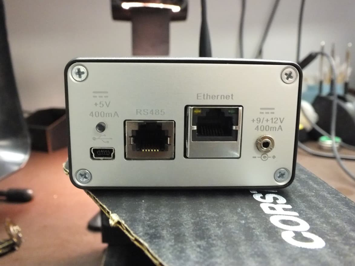
RMK-RECZIGB1
Feb 07, 2013Wireless Transmitter Base for Data Acquisition System
Equipment Class
DTS - Digital Transmission System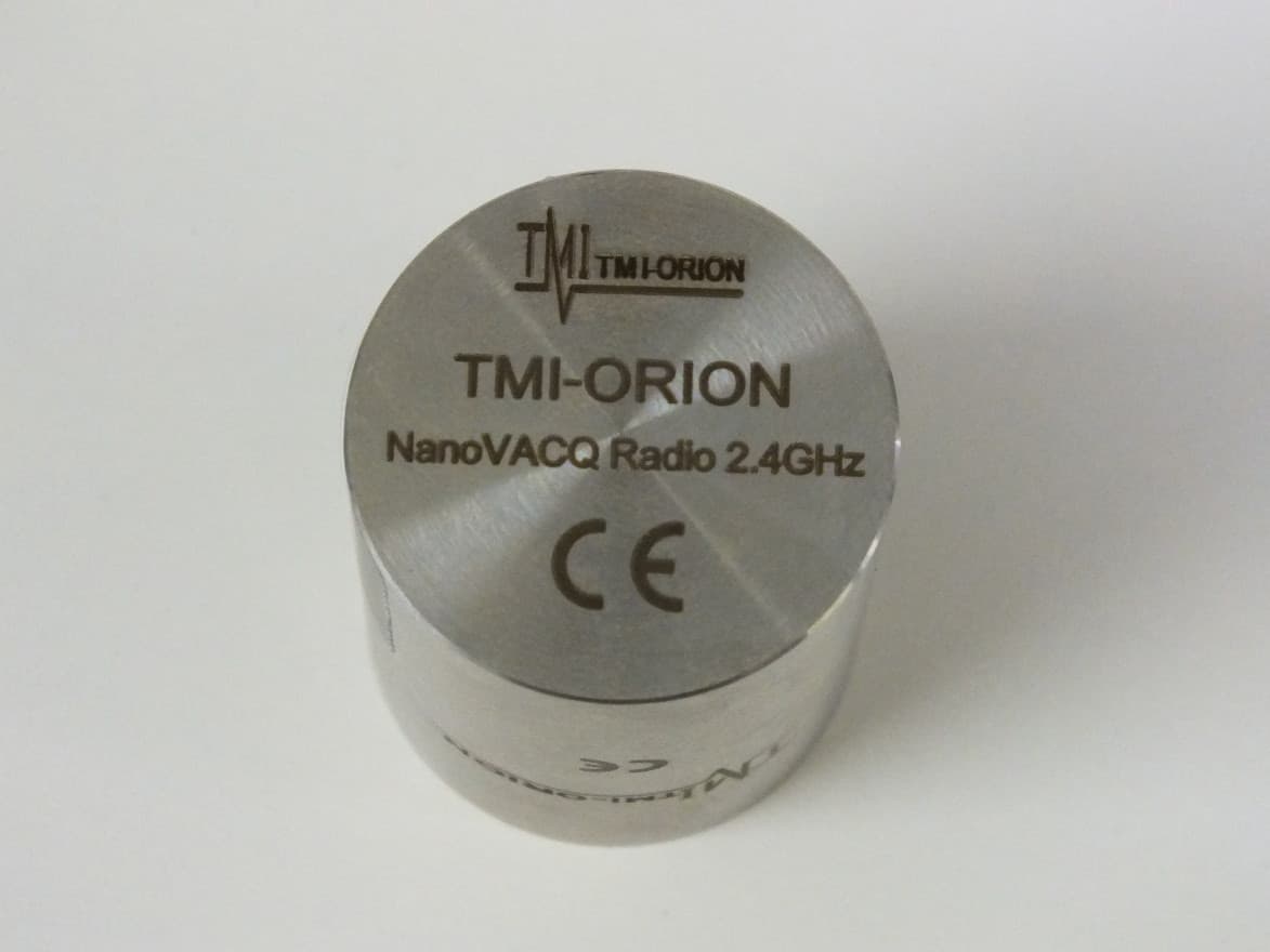
RMK-NVQZIGB1
Feb 05, 2013Wireless Data Acquisition System
Equipment Class
DTS - Digital Transmission System