RMXHSBUB-SDSNotebook
Intel Corporation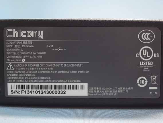
Click to zoom
Application Details
- Equipment Class
- DXX - Part 15 Low Power Communication Device Transmitter
- Date of Grant
- Mar 25, 2013
- Application Purpose
- Original Equipment
- Date of Application
- Mar 20, 2013
- Equipment Note
- Notebook
- Frequency Range
- 13.56000000 - 13.56000000
- Company
- Intel Corporation
- Country
- United States
Documents & Files
Document Text
Text extracted from the exhibit documents filed with the FCC. Open a document above to read the original.
Users Manual
Harris beach User Guide (Model: HSBUB-SDS) Jan 2013 Revision 0.6 Intel Confidential 2 Revision History Revision Number Description Revision Date 0.5 Initial release Jan.2013 0.6 Add caution about battery Jan.2013 3 Safety precautions i. Please only use the power adapter in the accessories box to charge the internal battery of the system. ii. Battery is not User-serviceable, do not attempt to remove battery. iii. Do NOT remove, disassemble, puncture, drop, crush the internal battery pack or expose to fire or temperatures above 100. Do NOT drop the system to water. iv. Excessive sound pressure from earphones and headphones can cause hearing loss. v. DO NOT place the ultra-book on an uneven or unstable work surfaces. This may cause the unit to fall, hence, damaged. vi. Risk of explosion if battery is replaced by an incorrect type. vii. Dispose of used batteries according to the instructions. viii. The 5150-5250MHz is limited to used indoor only. 4 Contents 1 Hardware setup.................................................................................................................. 5 1.1 Top View ...........................................................................................................................5 1.2 Bottom View .....................................................................................................................6 1.3 Right side ..........................................................................................................................7 1.4 Left Side............................................................................................................................8 2 Using your Notebook PC................................................................................................. 9 2.1 Getting started ...................................................................................................................9 2.2 Gestures for the touch screen ............................................................................................9 2.3 Using the keyboard ......................................................................................................... 11 2.4 Turn your Notebook PC off ............................................................................................ 11 3 Trouble shooting.............................................................................................................. 12 4 Appendices......................................................................................................................... 13 5 1 Hardware setup Getting to know the model: HSBUB-SDS 1.1 Top View 1) Microphone The built-in microphone can be used for video conferencing, voice narrations, or simple audio recording. 2) Camera indicator The camera indicator lights up when the built-in camera is in use. 3) Camera The built-in camera allows you to take pictures or record videos. 4) ALS (Ambient light sensor) The ALS allows the system to change the display backlight automatically according the ambient light. 5) Display panel This high-definition display panel provides excellent viewing features for 6 Photos, videos, and other multimedia files. Note: HSBUB-SDS is equipped with touch-enabled panel, allowing you to operate using touch gestures. 6) Number Lock indicator This indicator lights up when the number lock function is activated. 7) Power button (with power LED indicator) Press the power button can turn on/off Notebook PC. You can also use it to put your PC into sleep or hibernate mode and wake it up from sleep or hibernate mode. The power LED lights up when the Notebook PC is turned on. 8) Keyboard The keyboard provides full size keys for typing, it also enables you to use the function keys, allows quick access to Windows. 9) Capital lock indicator This indicator lights up when the capital lock function is activated 10) Touchpad The touchpad allows the use of multi-gestures to navigate onscreen. It also simulates the functions of a regular mouse. 1.2 Bottom View 7 1.3 Right side 1) SIM Card port The standard SIM card can be plugged into this port for the built-in 3G module. 2) Mini HDMI port This port is for a High-Defnition Multimedia Interface (HDMI) connector. 3) USB3.0 port This Universal Serial Bus 3.0 (USB 3.0) port provides a transfer rate of up to 5 Gbit/s and is backward compatible to USB 2.0 4) Power (DC) input port with two color battery charge indicator Insert the bundled power adapter into this port to charge the battery pack and supply power to your Notebook PC. The two-color LED provides a visual indication of the battery’s charge status. Refer to the following table for details: IMPORTANT! Use only the bundled power adapter to charge the battery pack and supply power to your Notebook PC. 8 Power adapter information: Chicony A12-045N2A - Input : 100~240V /1.3A , 50~60Hz - output: 19V / 2.37A, 45W Delta ADP-45BE AA - Input : 100~240V /1.3A , 50~60Hz - output: 20V / 2.25A, 45W 1.4 Left Side 1) Headphone/microphone combo jack port This port allows you to connect your Notebook PC’ to amplified speakers or headphones. You can also use this port to connect your Notebook PC to an external microphone. 2) USB3.0 port This Universal Serial Bus 3.0 (USB 3.0) port provides a transfer rate of up to 5 Gbit/s and is backward compatible to USB 2.0 3) SD card reader port This Notebook PC has a single built-in memory card reader slot that support SD card formats. 9 2 Using your Notebook PC 2.1 Getting started 1) Connect the AC power cord to the AC/DC adapter, Plug the AC power adapter into a 100V~240V power source. Connect the DC power connector into your Notebook PC’s power (DC) input. 2) Lift to open the display panel. 3) Press the power button. 2.2 Gestures for the touch screen 10 11 2.3 Using the keyboard The function keys on your Notebook PC’s keyboard can trigger the following commands: Function keys Expectation Fn+F1 Puts the Notebook PC into Sleep mode Fn+F2 Display switch Fn+F3 Display brig…
Text truncated - open the document above for the full version.
Cover Letter(s)
Date: 03/15/2013 Declaration Letter To Whom It May Concern: Subject: Letter of Declaration FCC ID: RMXHSBUB-SDS; IC: 1000V-HSBUBSDS We are seeking FCC approval of the Intel Notebook (model name HSBUB-SDS) which contains Wi-Fi, BT, and NFC together with a certified WWAN module under FCC ID: QISMU736, IC: 6369A-MU736. The device has been tested pursuant to the following FCC rules: Subpart C of Part 15.247 of FCC Rules (CFR 47) and 15.225, Intentional Radiators Subpart E of Part 15 of FCC Rules (CFR 47), UNII Devices AUDIX Technology Corporation is a duly authorized agent. A copy of a letter of authorization is included in the filing of this application. If there are any questions or if further information is needed, please contact AUDIX Technology Corporation for assistance. Sincerely, _______________________________________ Ben Cheng/Manager AUDIX Technology Corporation
Cover Letter(s)
Intel Corporation Contact Address: 2200 Mission College Blvd. Santa Clara, CA 95054-1549, USA Date: February 28, 2013 Federal Communications Commission Authorization and Evaluation Division 1435 Oakland Mills Road Columbia, MD 21046 Subject: Letter of Authorization FCC ID: RMXHSBUB-SDS To whom it may concern, Please be notified that I, Yan Rao have designated Ben Cheng in AUDIX Technology Corporation as the person being responsible for this project and to sign the form 731 and other documentation. Any and all acts carried out by Ben Cheng in AUDIX Technology Corporation on the matters relating to all processes required in the FCC approval and any communication needed with the national authority, shall have the same legal authority as acts on our own behalf. We further certify that neither the applicant nor any party to this application, as defined in 47 CFR Ch. 1.2002 (b), is subject to a denial to Federal benefits, that include FCC benefits, pursuant to section 5301 of the Anti-Drug Abuse Act of 1998, 21 U.S.C. 835(a). This authorization is limited to the product of as following: FCC ID: RMXHSBUB-SDS If you have any questions please feel free to contact Yan Rao at +86-21-6116-6159. Sincerely, ________________________ Yan Rao Intel Corporation Phone:+86-21-6116-6159. E-mail address: [email protected]
Cover Letter(s)
Intel Corporation Contact Address:2200 Mission College Blvd. Santa Clara, CA 95054-1549, USA Date: March 14, 2013 Federal Communications Commission Authorization and Evaluation Division 1435 Oakland Mills Road Columbia, MD 21046 Subject: Permanent Confidentiality Request FCC ID: RMXHSBUB-SDS Pursuant to Sections 0.457 and 0.459 of the Commission’s Rules, we hereby request Permanent Confidential treatment of information accompanying this application as outlined below: Schematics Block Diagram Operation Description The above materials contain trade secrets and proprietary information not customarily released to the public. The public disclosure of these materials may be harmful to the applicant and provide unjustified benefits to its competitors. If you have any questions please feel free to contact Yan Rao at +86-21-6116-6159. Sincerely, ________________________ Yan Rao Intel Corporation Phone:+86-21-6116-6159. E-mail address: [email protected]
Cover Letter(s)
For the following information Ref. File No.: C1M1212198 Product : Notebook Model Number : HSBUB-SDS Brand Name : Intel Applicant : Intel Corporation S tandards : FCC CFR 47 Part 15 Subpart B/Oct. 2012 and CISPR 22/1997 (Class B Limit) and ICES-003 We hereby certify that the above product has been tested by us and complied with the FCC and IC official limits. These products might be marketed at the US accordance to FCC Rule based on the standard CFR 47 Part 2 and Part 15 Class B Equipment Regulations. The test was performed accordance to the procedures from ANSI C63.4-2009. The test data & results are issued on the test report no. EM-F1020031. Signature _____________________________ Leon Liu/Deputy General Manager Date: Jan. 10, 2013 Test Laboratory: AUDIX Technology Corporation, EMC Department NVLAP Lab. Code: 200077-0 FCC OET Designation: TW1004 Web Site: www.audixtech.com The statement is based on a single evaluation of one sample of the above-mentioned products. It does not imply an assessment of the whole production and does not permit the use of the test lab logo. NVLAP Lab Code 200077-0
External Photos
Intel Corporation Notebook FCC ID:RMXHSBUB-SDS IC:1000V-HSBUBSDS EUT External Photos Figure 1 Notebook (Front and Side View) Figure 2 Notebook (Back and Side View) Intel Corporation Notebook FCC ID:RMXHSBUB-SDS IC:1000V-HSBUBSDS Figure 3 Notebook (Side View) Figure 4 Notebook (Side View) Intel Corporation Notebook FCC ID:RMXHSBUB-SDS IC:1000V-HSBUBSDS Figure 5 Notebook (Bottom View) Figure 6 Notebook (Panel and Keyboard View) Intel Corporation Notebook FCC ID:RMXHSBUB-SDS IC:1000V-HSBUBSDS Figure 7 Delta, ADP-45BE AA AC Adapter (Front and Side View) Figure 8 Delta, ADP-45BE AA AC Adapter (Front and Side View) Intel Corporation Notebook FCC ID:RMXHSBUB-SDS IC:1000V-HSBUBSDS Figure 9 Delta, ADP-45BE AA AC Adapter (Back View) Figure 10 Delta, ADP-45BE AA AC Adapter (Back View) Intel Corporation Notebook FCC ID:RMXHSBUB-SDS IC:1000V-HSBUBSDS Figure 11 Chicony, A12-045N2A AC Adapter (Front and Side View) Figure 12 Chicony, A12-045N2A AC Adapter (Front and Side View) Intel Corporation Notebook FCC ID:RMXHSBUB-SDS IC:1000V-HSBUBSDS Figure 13 Chicony, A12-045N2A AC Adapter (Back View) Figure 14 Chicony, A12-045N2A AC Adapter (Power Cord)
ID Label/Location Info
Intel Corporation Notebook FCC ID:RMXHSBUB-SDS IC:1000V-HSBUBSDS FCC ID & IC Label Location z Label Placement Location z FCC ID & IC Label Format FCC ID & IC Label Placement Location
Internal Photos
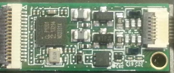
Intel Corporation Notebook FCC ID:RMXHSBUB-SDS IC:1000V-HSBUBSDS EUT Internal Photos Figure 15 Internal View (Removed Cover) Figure 16 Internal View 3G Module WLAN/BT Module NFC Module Intel Corporation Notebook FCC ID:RMXHSBUB-SDS IC:1000V-HSBUBSDS Figure 17 Internal View (FAN) Figure 18 Internal View (RAM, Front View) Intel Corporation Notebook FCC ID:RMXHSBUB-SDS IC:1000V-HSBUBSDS Figure 19 Internal View (RAM, Back View) Figure 20 Internal View (3G Module, Front View) Intel Corporation Notebook FCC ID:RMXHSBUB-SDS IC:1000V-HSBUBSDS Figure 21 Internal View (3G Module, Front View) Figure 22 Internal View (3G Module, Back View ) Intel Corporation Notebook FCC ID:RMXHSBUB-SDS IC:1000V-HSBUBSDS Figure 23 Internal View (WiFi+BT Module, Front View) Figure 24 Internal View (WiFi+BT Module, Front View) Intel Corporation Notebook FCC ID:RMXHSBUB-SDS IC:1000V-HSBUBSDS Figure 25 Internal View (WiFi+BT Module, Back View) Figure 26 Internal View (Main Board, Front View) Intel Corporation Notebook FCC ID:RMXHSBUB-SDS IC:1000V-HSBUBSDS Figure 27 Internal View (Main Board, Back View) Figure 28 Internal View Intel Corporation Notebook FCC ID:RMXHSBUB-SDS IC:1000V-HSBUBSDS Figure 29 Internal View (Touch PAD Board, Front View) Figure 30 Internal View (Touch PAD Board, Back View) NFC Antenna Intel Corporation Notebook FCC ID:RMXHSBUB-SDS IC:1000V-HSBUBSDS Figure 31 Internal View (Keyboard) Figure 32 Internal View (Removed Cover) Intel Corporation Notebook FCC ID:RMXHSBUB-SDS IC:1000V-HSBUBSDS Figure 33 Internal View Figure 34 Internal View (LCD Panel, Back View) 3G Antenna (Main) WLAN/BT Antenna (AUX) 3G Antenna (AUX) WLAN/BT Antenna (Main) Intel Corporation Notebook FCC ID:RMXHSBUB-SDS IC:1000V-HSBUBSDS Figure 35 Internal View (Control Board) Figure 36 Internal View (NFC Module, Front View) Intel Corporation Notebook FCC ID:RMXHSBUB-SDS IC:1000V-HSBUBSDS Figure 37 Internal View (NFC Module, Back View)
Test Report
FCC ID. RMXHSBUB-SDS IC: 1000V-HSBUBSDS Page 1 of 34 AUDIX Technology Corporation Report No. EM-F1020112 APPLICATION FOR CERTIFICATION On Behalf of Intel Corporation Notebook Models No.: HSBUB-SDS FCC ID: RMXHSBUB-SDS IC: 1000V-HSBUBSDS Brand: Intel Prepared for : Intel Corporation 2200 Mission College Blvd. Santa Clara, CA 95054-1549, USA Prepared By : AUDIX Technology Corporation EMC Department No. 53-11, Dingfu, Linkou Dist., New Taipei City 244, Taiwan, R.O.C. Tel : (02) 2609-9301, 2609-2133 Fax: (02) 2609-9303 File Number : C1M1212198 Report Number : EM-F1020112 Date of Test : Feb. 01 ~ 04, 2013 Date of Report : Feb. 06, 2013 FCC ID. RMXHSBUB-SDS IC: 1000V-HSBUBSDS Page 2 of 34 AUDIX Technology Corporation Report No. EM-F1020112 TABLE OF CONTENTS Description Page TEST REPORT CERTIFICATION ............................................................................................. 3 1. SUMMARY OF MEASUREMENTS AND RESULTS .................................................... 4 2. GENERAL INFORMATION .............................................................................................. 5 2.1. Description of Device (EUT).........................................................................................................5 2.2. Antenna Information......................................................................................................................8 2.3. Description of Key Component Lists ..........................................................................................10 2.4. Tested Supporting System Details ...............................................................................................12 2.5. Description of Test Facility .........................................................................................................13 2.6. Measurement Uncertainty............................................................................................................13 3. POWERLINE CONDUCTED EMISSION MEASUREMENT..................................... 14 3.1. Test Equipment ............................................................................................................................14 3.2. Block Diagram of Test Setup.......................................................................................................14 3.3. Powerline Conducted Emission Limit (§15.207, RSS-Gen §7.2.2/Table 2) ...............................14 3.4. Operating Condition of EUT .......................................................................................................15 3.5. Test Procedure .............................................................................................................................15 3.6. Powerline Conducted Emission Measurement Results................................................................15 4. RADIATED SPURIOUS EMISSION MEASUREMENT (IN-BAND) ......................... 18 4.1. Test Equipment ............................................................................................................................18 4.2. Block Diagram of Test Setup.......................................................................................................18 4.3. IN-Band Radiated Spurious Emission Limit (§15.225(a)(b)(c), RSS-210 A2.6) ........................19 4.4. Operating Condition of EUT .......................................................................................................19 4.5. Test Procedure .............................................................................................................................19 4.6. Radiated Emission Measurement Results....................................................................................20 5. RADIATED SPURIOUS EMISSION MEASUREMENT (OUT-BAND) ..................... 21 5.1. Test Equipment ............................................................................................................................21 5.2. Block Diagram of Test Setup.......................................................................................................21 5.3. Radiated Emission Limits [§15.209, §15.209(d), RSS-210 §2.7/Table 2, RSS-210 (A2.6)] ......22 5.4. Operating Condition of EUT .......................................................................................................22 5.5. Test Procedure .............................................................................................................................22 5.6. Radiated Emission Measurement Results....................................................................................23 6. 20dB BANDWIDTH MEASUREMENT .......................................................................... 26 6.1. Test Equipment ............................................................................................................................26 6.2. Block Diagram of Test Setup.......................................................................................................26 6.3. Specification Limits [§15.215(c)]................................................................................................26 6.4. Operating Condition of EUT .......................................................................................................26 6.5. Test Procedure .............................................................................................................................26 6.6. Test Results..................................................................................................................................27 7. FREQUENCY STABILITY MEASUREMENT ............................................................. 28 7.1. Test Equipment ............................................................................................................................28 7.2. Block Diagram of Test Setup.......................................................................................................28 7.3. Specification Limits [§15.225(c), RSS-210 (A2.6)]…
Text truncated - open the document above for the full version.
Test Setup Photos
FCC ID. RMXHSBUB-SDS IC: 1000V-HSBUBSDS Page 31 of 34 AUDIX Technology Corporation Report No. EM-F1020112 9. PHOTOGRAPHS 9.1. Photos of Conducted Disturbance Measurement FRONT VIEW OF CONDUCTED MEASUREMENT BACK VIEW OF CONDUCTED MEASUREMENT FCC ID. RMXHSBUB-SDS IC: 1000V-HSBUBSDS Page 32 of 34 AUDIX Technology Corporation Report No. EM-F1020112 9.2. Photos of Radiated Emission Measurement (IN-Band) FCC ID. RMXHSBUB-SDS IC: 1000V-HSBUBSDS Page 33 of 34 AUDIX Technology Corporation Report No. EM-F1020112 9.3. Photos of Radiated Emission Measurement (IN-Band) 9.3.1. Frequency Range 9kHz-30MHz 9.3.2. Frequency Range 30MHz-1GHz FCC ID. RMXHSBUB-SDS IC: 1000V-HSBUBSDS Page 34 of 34 AUDIX Technology Corporation Report No. EM-F1020112 9.4. Photo of 20dB Bandwidth & Frequency Stability Measurement
Contact Information
Applicant
Mike Lowe(Product Regulatory Engineer)
Technical Contact
Audix TechnologyBen Cheng
[email protected]88626099301
No. 53-11 Dingfu, Linkou District · New Taipei City · Taiwan
Test Firm
Audix Technology CorporationLeon Liu
Technical Specifications
| # | Rule Parts | Frequency Range | Power Output |
|---|---|---|---|
| 1 | 15C | 13.56 MHz - 13.56 MHz | - |
Other Applications from Intel Corporation
RMXSKL21SDS
Aug 27, 2015SKL21-SDS
Equipment Class
DXX - Part 15 Low Power Communication Device Transmitter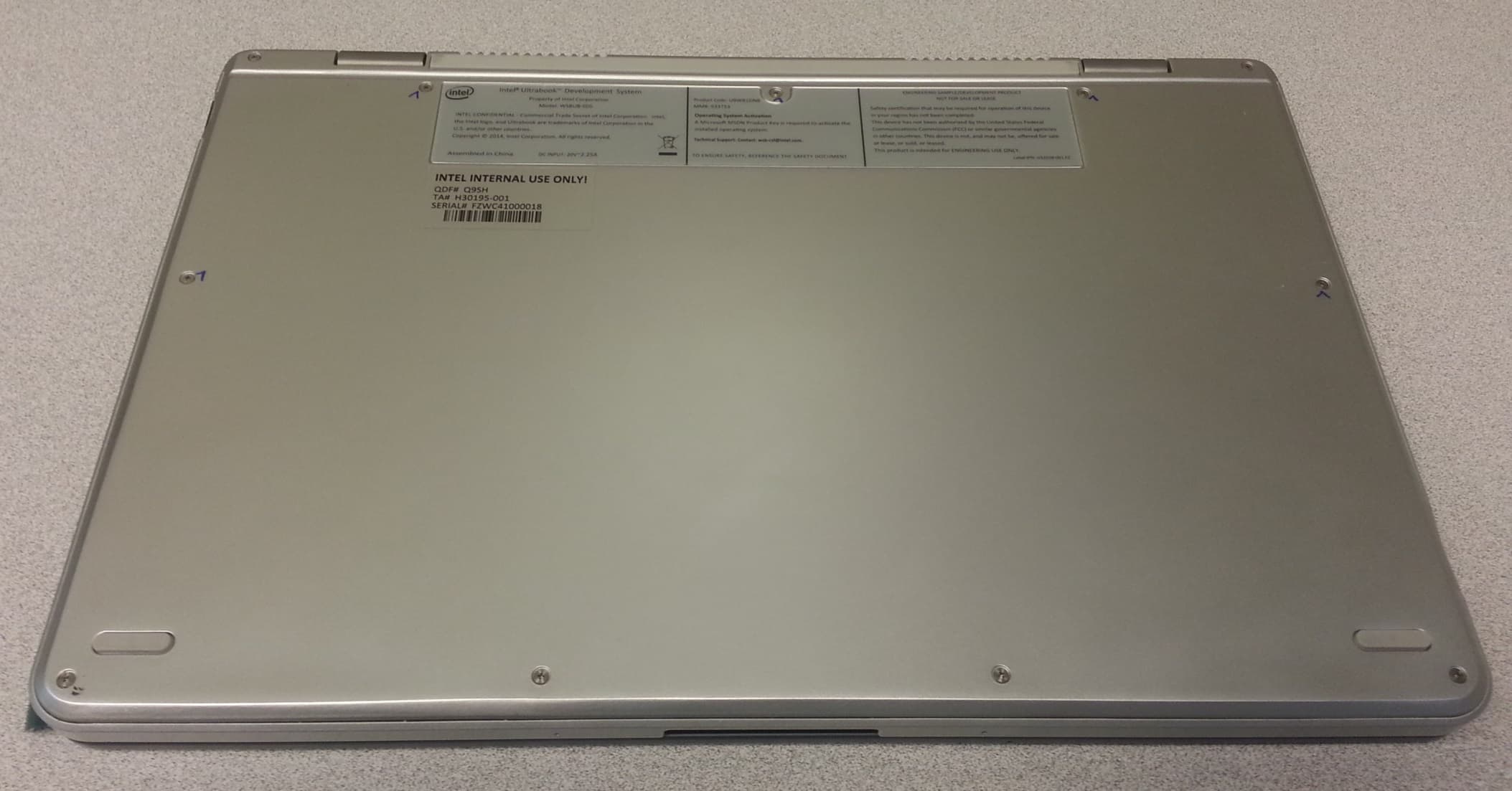
RMXWSBUB-SDS
Oct 01, 2014WSBUB-SDS
Equipment Class
DXX - Part 15 Low Power Communication Device Transmitter