RMYNT350FP07350W TRANSMITTER
NiCOM USA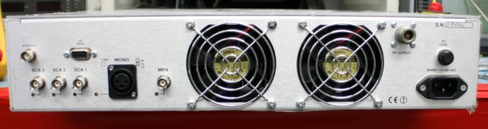
Click to zoom
Application Details
- Equipment Class
- TBC - Licensed Broadcast Station Transmitter
- Date of Grant
- Jul 26, 2007
- Application Purpose
- Original Equipment
- Date of Application
- Jul 26, 2007
- Equipment Note
- 350W TRANSMITTER
- Frequency Range
- 87.50000000 - 108.00000000
- Company
- NiCOM USA
- Country
- United States
Documents & Files
Document Text
Text extracted from the exhibit documents filed with the FCC. Open a document above to read the original.
Users Manual
1 TABLE OF CONTENTS CHAPTER 1 Transmitter General Description And Installation Procedures Page 2 Remote Control Feature Page 5 Analog telemetry Option Page 7 Programming the NT 350 Page 8 CHAPTER 2 Electrical Specifications Page 13 Mechanical Specifications Page 15 CHAPTER 3 350 W schematics and components list Page 16 2 CHAPTER 1 GENERAL DESCRIPTION NT 350 Transmitter - Exciter INTRODUCTION The NT-350-LCD is a highly integrated broadband solid-state Mos-Fet FM transmitter of 350W rated power, fitted in a 3 unit rack, which do not require any specific calibration to operate in the 87.5 ÷ 108 MHz frequency range. The unit is microprocessor controlled with an optional PC interface. Its compact size, high efficiency, wide mains range acceptance, low maintenance requirements and broadband construction, make this amplifier ideal in medium power repeaters, in unattended posts and as a reserve. Its sturdy, modular mechanical and electrical construction guarantees a high MTBF and an easy maintenance. The modules are easily identifiable and inspectable with few interconnections each with the other, through multi-pole connectors. The nominal RF output power is obtained over the full FM range is particularly stable against time, temperature and frequency variations being ALC regulated, with a front panel adjustment. The output power may be varied from a minimum level to the nominal level and the frequency varied over the full FM range, without retouching the drive power or any other adjustment than the ALC control. The output stage has a reverse intermodulation figure, which is lower than standard bipolar construction, due to the all Mos-Fet design and approaches that of tube equipment. A simple metering and alarm section completes the amplifier, permitting an easy check of the functioning with few, unambiguous readings. The front panel displays forward, reflected power and modulation measures. It is possible to change the frequency of the unit from the front panel, password protected. The whole assembly is designed in accordance with the CCIR, FCC and tighter international norms and conforms to the recent, strict requirements for EMI susceptance and emission. 3 INSTALLATION After unpacking the unit, check for any mechanical damage or loose parts inside. If there is any transportation damage, inform the supplier immediately and do not put the module into operation. The applicable voltage is 110 or 220v depending on how the unit was ordered. Please check the back of the unit for the voltage that the unit was set to, and if it is the wrong one, please call Nicom for instruction on how to set the voltage. Ensure that the station’s ground system connections have a ground resistance of less than 5 ohms. The equipment’s rack or cabinet must be effectively grounded. Check that the transmitter’s main switch is off. Connect the power cord to the AC plug. STARTING PROCEDURE Connect the antenna cable to the ‘N’ type connector on the back of the unit. The antenna system must be set up to operate at the transmitter’s working frequency. ATTENTION Antenna matching is extremely crucial for FM transmitters. Operate this unit only after verifying good matching. Mismatching will decrease the communication distance and unduly stress the semiconductors. Turn on the transmitter. You should see the "WAIT" message appear on the LCD Display. After few seconds the green LED “PLL LOCK” should turn on. This indicates that the frequency is locked on the programmed value. In the display will appear a sequence of squares. After few more seconds the “RF ENABLE” green LED will come on. This indicates that RF power is being delivered to the output connector on the back. You can now increase the output power through the small trimpot located in the front panel and identified with " RF ADJ." Increase slowly till you reach the power you need; keep always an eye at the Reflected power reading to verify that the antenna is well operating. The indication of the reflected power is on the right side of the display "RFL". Once you have reached the desired power level, you should wait till the unit warms up (30 minutes) 4 Now you can input modulation. For MONO operation connect your signal to the XLR connector or BNC, Depending on the model. Following the connecting instructions printed on the back of the transmitter and then regulate the input level with the apposite trimmer. For stereo input, use the BNC connector labeled “MPX”. Regulate the audio with the apposite trimmer. Note:Be sure that the modulation level is close to but not more than 75KHz. 75KHz is 100% modulation. Lower modulation level will decrease the S/N value while over-modulation (>100%) will cause distortion at the receiver and it is against current regulations. 5 REMOTE CONTROL FEATURE The NT 350 is equipped with a 9 pin RS 232 connector that allows all the mains telemetry functions. The software is supplied with the unit and with this CD rom it's possible to monitor and to change the main parameters ot the NT 350 on the computer's screen. The NT 350 is also supplied with the interlock connector that allows to switch the power on and off simply by grounding the inner conductor of the BNC. NOTE: The CD (optional) contains the remote control software of the NT 350. If a CD was not ordered, please check Nicom website (www.NicomUsa.com ) where the latest version of the software is available for download. REMOTE CONTROL SOFTWARE INSTALLATION The NT 350 comes with a Serial port RS 232. This port allows a Bi-Directional remote control of the unit from a PC. INSTALLING THE SOFTWARE 1. Insert the NT 350 CD-ROM into the CD drive. 2. Run Setup.exe file found in the main folder of the CD-ROM. The installation will continue automatically asking only for the name of the folder of the hard drive where the program will be installed. It will be necessary to reboot the computer. 3. Once installed, the Tx_Nicom program icon can be recalled by clicking : Start - Programs - Tx_Nicom icon. CON…
Text truncated - open the document above for the full version.
Cover Letter(s)
NicomUsa, Inc 2626 Southport Way suite “B” National City, CA 91950 Tel. (619) 477-6298 Fax. (619) 477-6296 To: TIMCO ENGINEERING From: Dario Piagentini Re: Confidentiality Request Date: 6/14/07 Confidentiality Request regarding application for certification of FCC ID: RMYNT350FP07 Dear Sir or Madam: Pursuant to Sections 0.457 and 0.459 of the Commission’s Rules, we hereby request confidential treatment of information accompanying this application as outlined below: Schematics 352AUT7 Schematics.pdf Block Diagram 352AUT7 BlockDiagram.pdf Circuit Description 352AUT7 Circuit Description.pdf Tuning procedure 352AUT7 TuningProcedure.pdf The above materials contain trade secrets and proprietary information not customarily released to the public. The public disclosure of these materials may be harmful to the applicant and provide unjustified benefits to its competitors. The applicant understands that pursuant to Section 0.457 of the Rules, disclosure of this application and all accompanying documentation will not be made before the date of the Grant for this application. Thank you Dario Piagentini Vice-President NicomUsa, Inc
External Photos
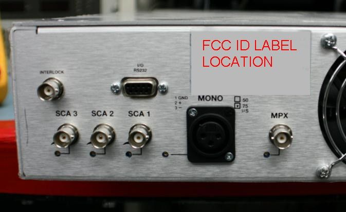
NICOM USA, INC. FCC ID: RMYNT350 EXTERNAL PHOTOS
Internal Photos
NICOM USA, INC. FCC ID: RMYNT350 INTERNAL PHOTOS RF MODULE RF MODULE BACK INTERNAL CHASSIS VIEW M BOARD – TOP VIEW M BOARD – TOP VIEW – SHIELDS REMOVED MBOARD – REAR VIEW
Test Report
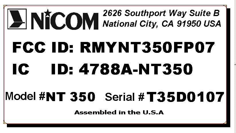
TIMCO ENGINEERING INC. 849 NW State Road 45 Newberry, Florida 32669 http://www.timcoengr.com 888.472.2424 F 352.472.2030 email: [email protected] APPLICANT: NiCOM USA, INC. FCC ID: RMYNT350FP07 REPORT #: N\Nicom\352AUT7\352AUT7TestReport.doc COVER SHEET Test Report Product Name: FM TRANSMITTER FCC ID: RMYNT350FP07 Applicant: NiCOM USA, INC. 2626 SOUTHPORT WAY SUITE B NATIONAL CITY, CA 91950 Date Receipt: 2/6/2007 Date Tested: 2/22/2007 TIMCO ENGINEERING INC. 849 NW State Road 45 Newberry, Florida 32669 http://www.timcoengr.com 888.472.2424 F 352.472.2030 email: [email protected] APPLICANT: NiCOM USA, INC. FCC ID: RMYNT350FP07 REPORT #: N\Nicom\352AUT7\352AUT7TestReport.doc TABLE OF CONTENTS APPLICANT: NiCOM USA, INC. FCC ID: RMYNT350FP07 TABLE OF CONTENTS LIST TEST REPORT CONTAINING: PAGE 1.........GENERAL INFORMATION & TECHNICAL DESCRIPTION PAGE 2.........TECHNICAL DESCRIPTION & RF POWER OUTPUT PAGE 3.........MODULATION CHARACTERISTICS AUDIO FREQUENCY RESPONSE GRAPH AUDIO LOW PASS FILTER PAGE 4.........OCCUPIED BANDWIDTH PAGE 5-7.......OCCUPIED BANDWIDTH PLOTS PAGE 8.........SPURIOUS EMISSION AT ANTENNA TERMINALS PAGE 9.........METHOD OF MEASURING SPURIOUS EMISSIONS AT ANTENNA TERMINALS PAGE 10-11.....FIELD STRENGTH OF SPURIOUS EMISSIONS PAGE 12........METHOD OF MEASURING RADIATED SPURIOUS EMISSIONS PAGE 13........POWER LINE CONDUCTED INTERFERENCE PAGE 14-15.....POWER LINE CONDUCTED PLOTS PAGE 16........FREQUENCY STABILITY PAGE 17-18.....EQUIPMENT LIST EXHIBITS INCLUDING: BLOCK DIAGRAM SCHEMATICS PARTS LIST USERS MANUAL LABEL SAMPLE LABEL LOCATION EXTERNAL PHOTOGRAPHS INTERNAL PHOTOGRAPHS TUNING PROCEDURE OPERATIONAL DESCRIPTION TEST SET UP PHOTOGRAPHS TIMCO ENGINEERING INC. 849 NW State Road 45 Newberry, Florida 32669 http://www.timcoengr.com 888.472.2424 F 352.472.2030 email: [email protected] APPLICANT: NiCOM USA, INC. FCC ID: RMYNT350FP07 REPORT #: N\Nicom\352AUT7\352AUT7TestReport.doc Page 1 of 18 GENERAL INFORMATION REQUIRED FOR TYPE ACCEPTANCE 2.1033 NiCOM USA, INC. will manufacture the FCC ID: RMYNT350FP07 in quantity, for use under FCC RULES PART 73.801, LOW POWER FM BROADCAST STATIONS (LPFM). 2.1033(c)(4) TECHNICAL_DESCRIPTION Type of Emission: 74KF3E Bn = 2M + 2DK M = 15000 D = 22KHz (Peak Deviation) K = 1 Bn = 2(15K) + 2(22K)(1) = 74K ALLOWED AUTHORIZED BANDWIDTH = 200 kHz. 2.1033 (c)(5) Frequency Range: 87.5 - 108 MHz 2.1033 (c)(6) Power Range and Controls: The EUT can be adjusted from 5 Watts up to the maximum of the rated power. 2.1033 (c)(7) Maximum Output Power Rating: 350 Watts into 50 ohms resistive load. 2.1033 (c)(8) DC Voltages and Current into Final Amplifier: FINAL AMPLIFIER ONLY Vce = 48.0 Volts Ice = 12.0 A. 2.1033 (c)(9) Tune-up procedure. The tune-up procedure is given in the Exhibits. 2.1033(c)(10) Complete Circuit Diagrams: The circuit diagram and the block diagrams are included as part of the attached exhibits. 2.1033(c)(11) Photographs or drawings of the identification label & its location are included as part of the exhibits. 2.1033(c)(12) Photographs of both the externals & internals are included as part of the exhibits. 2.1033(c)(13) Digital Modulation is NOT used in this EUT. TIMCO ENGINEERING INC. 849 NW State Road 45 Newberry, Florida 32669 http://www.timcoengr.com 888.472.2424 F 352.472.2030 email: [email protected] APPLICANT: NiCOM USA, INC. FCC ID: RMYNT350FP07 REPORT #: N\Nicom\352AUT7\352AUT7TestReport.doc Page 2 of 18 2.1033(c)(14) Data required by ¶ 2.1046 Through ¶ 2.1057 is submitted below. 2.1046 RF_power_output. 73.267 (b)(2) RF power is measured by Direct Method power using TIA/EIA 603-C: 2004. OUTPUT POWER: 350W TIMCO ENGINEERING INC. 849 NW State Road 45 Newberry, Florida 32669 http://www.timcoengr.com 888.472.2424 F 352.472.2030 email: [email protected] APPLICANT: NiCOM USA, INC. FCC ID: RMYNT350FP07 REPORT #: N\Nicom\352AUT7\352AUT7TestReport.doc Page 3 of 18 2.1047(a)(b) Modulation characteristics: AUDIO_FREQUENCY_RESPONSE The audio frequency response was measured in accordance with ANSI/TIA-603-C-2004. The audio frequency response curve is shown below. Audio Frequency Response -0 +10 +2 +4 +6 +8 d B 100 20k 200 500 1k 2k 5k 10k Hz 2.1047(a)(b) AUDIO_LOW_PASS_FILTER The audio low pass filter is NA for this EUT. TIMCO ENGINEERING INC. 849 NW State Road 45 Newberry, Florida 32669 http://www.timcoengr.com 888.472.2424 F 352.472.2030 email: [email protected] APPLICANT: NiCOM USA, INC. FCC ID: RMYNT350FP07 REPORT #: N\Nicom\352AUT7\352AUT7TestReport.doc Page 4 of 18 2.1049 73.317(b-d) OCCUPIED BANDWIDTH: Any emission appearing on the frequency removed from the carrier between 120kHz and 240kHz inclusive must be attenuated at least 25 dB below the level of the un- modulated carrier. Compliance with this requirement will be deemed to show occupied bandwidth to be 240kHz or less. Any emission appearing on the frequency removed from the carrier by more than 240 kHz and up to and including 600 kHz must be attenuated at least 35 dB below the level of the un- modulated carrier. Any emission appearing on the frequency removed from the carrier by more than 600 kHz must be attenuated at least 43 + 10 Log(P) dB below the level of the un-modulated carrier, or 80 dB, whichever is the lesser attenuation. OCCUPIED BANDWIDTH MEASUREMENT REQUIREMENT: PART 73: 200kHz EMISSION BANDWIDTH. TIMCO ENGINEERING INC. 849 NW State Road 45 Newberry, Florida 32669 http://www.timcoengr.com 888.472.2424 F 352.472.2030 email: [email protected] APPLICANT: NiCOM USA, INC. FCC ID: RMYNT350FP07 REPORT #: N\Nicom\352AUT7\352AUT7TestReport.doc Page 5 of 18 2.1049 OCCUPIED BANDWIDTH PLOT (50 Hz) TIMCO ENGINEERING INC. 849 NW State Road 45 Newberry, Florida 32669 http://www.timcoengr.com 888.472.2424 F 352.472.2030 email: [email protected] APPLICANT: NiCOM USA, INC. FCC ID: RMYNT350FP07 REPORT #: N\Nicom\352AUT7\352AUT7TestReport.doc Page 6 of 18 2.1049 OCCUPIED BANDWIDTH PLOT (1 kHz) TIMCO ENGINEERING INC. 849 NW State Road 45 Newberry, Florida 32669 http://www.timcoengr.com …
Text truncated - open the document above for the full version.
Contact Information
Applicant
Dario Piagentini(Vice President)
Test Firm
Timco Engineering, Inc.Sid Sanders
Technical Specifications
| # | Rule Parts | Frequency Range | Power Output | Emission | Tolerance |
|---|---|---|---|---|---|
| 1 | 73 | 87.5 MHz - 108 MHz | 350 W | 74KF3E | 2000.0000000000 Hz |
Other Applications from NiCOM USA
RMYTSL910
Mar 15, 2020STL TRANSMITTER
Equipment Class
TBC - Licensed Broadcast Station Transmitter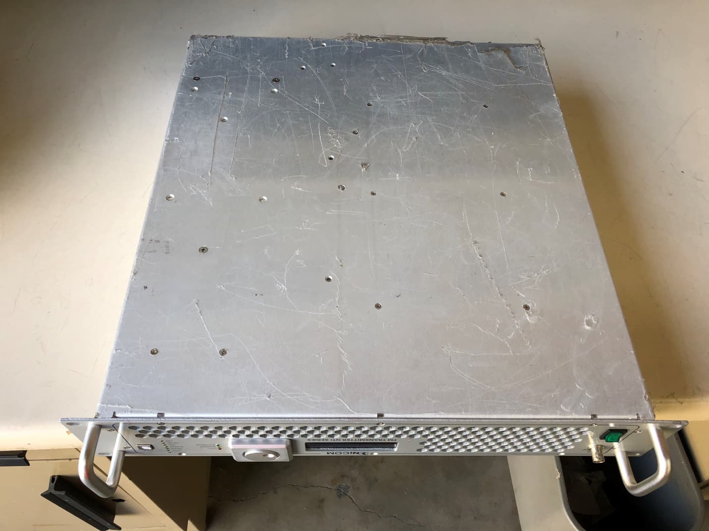
RMYNTI600
Mar 12, 2020FM BROADCAST TRANSMITTER
Equipment Class
TBC - Licensed Broadcast Station Transmitter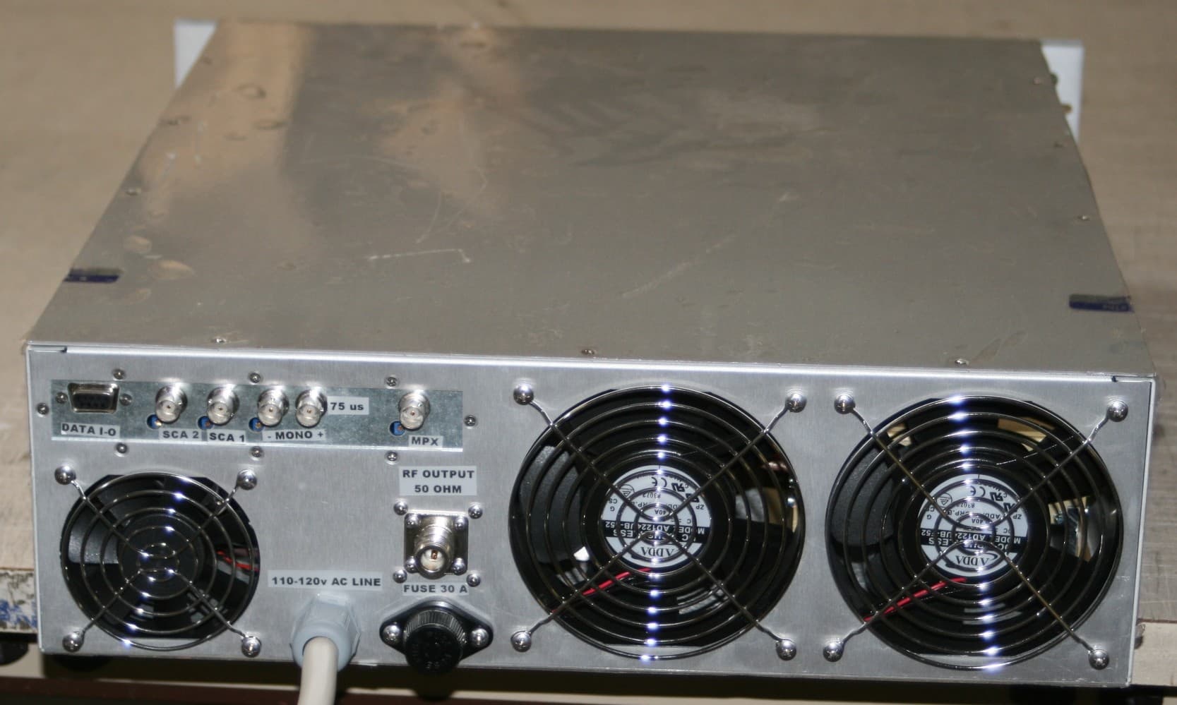
RMYNT500FP09
Nov 30, 2011FM TRANSMITTER
Equipment Class
TBC - Licensed Broadcast Station Transmitter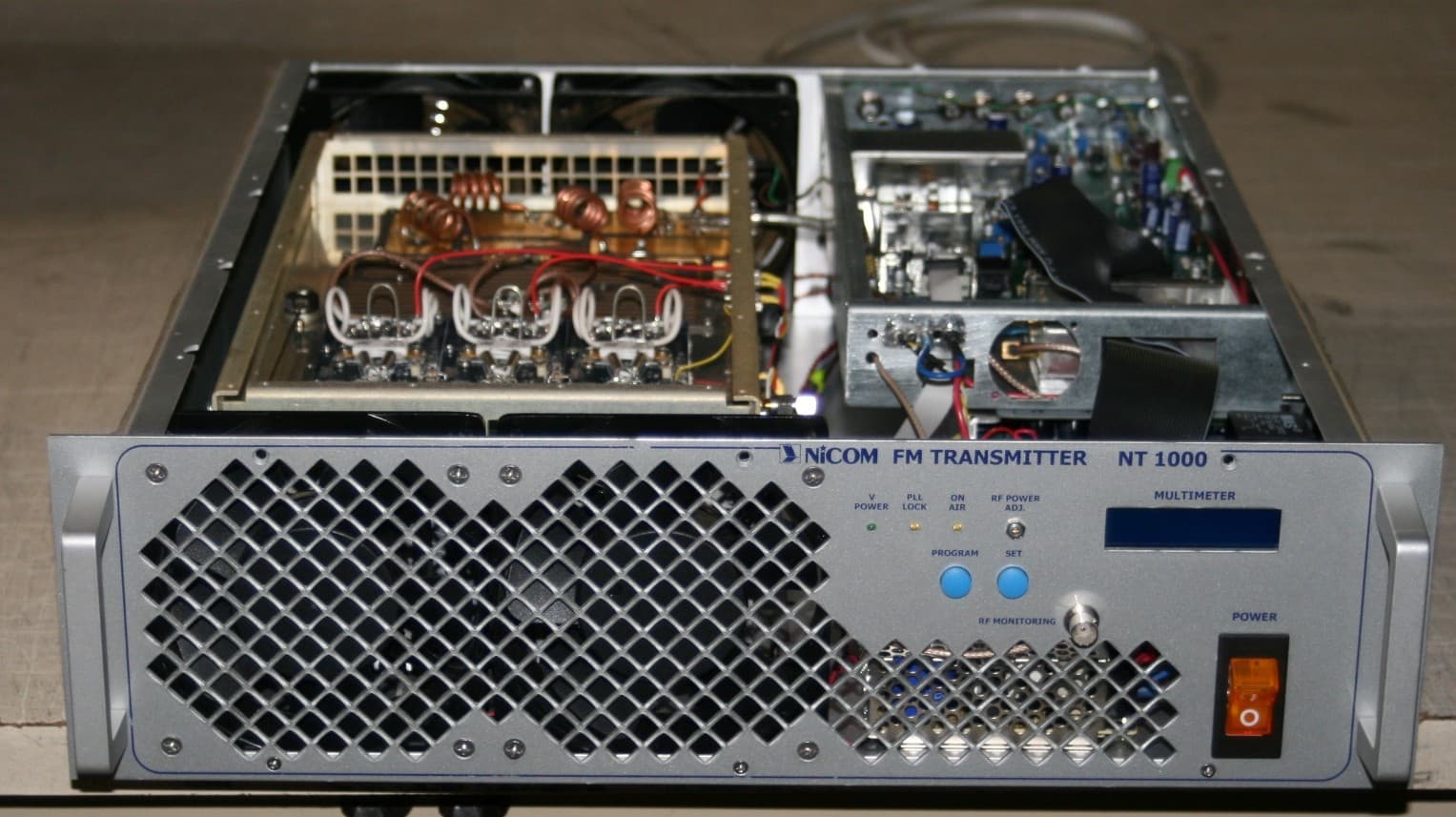
RMYNT1000FP09
Nov 30, 2011FM TRANSMITTER
Equipment Class
TBC - Licensed Broadcast Station Transmitter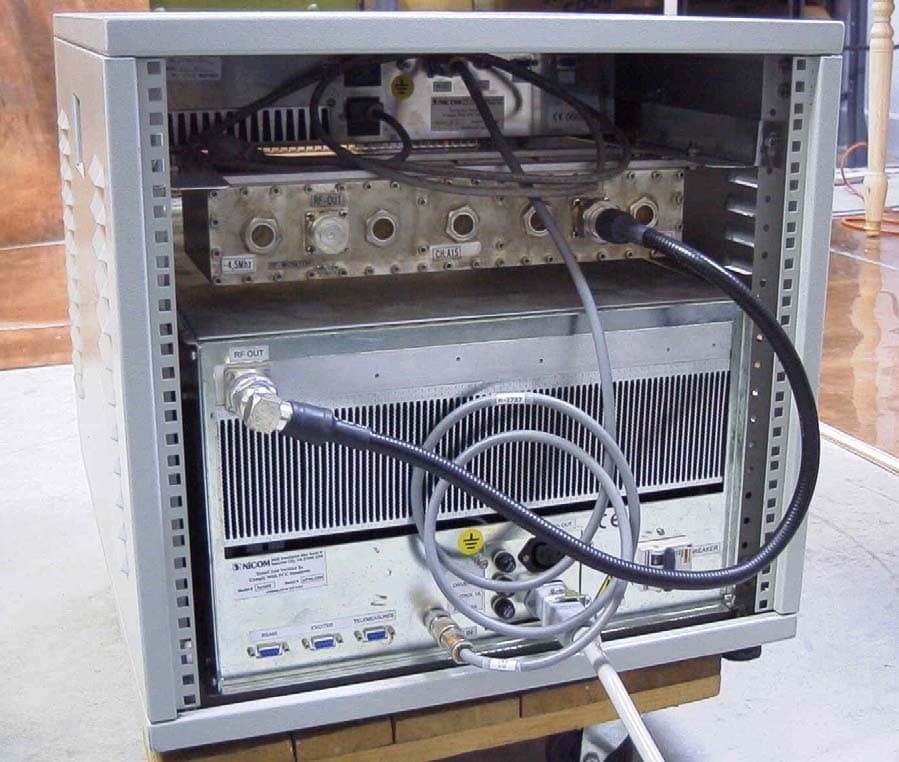
RMYAP1000FP06
Jul 30, 2007UHF TV AMPLIFIER
Equipment Class
TBC - Licensed Broadcast Station Transmitter