RMYNT500FP09FM TRANSMITTER
NiCOM USA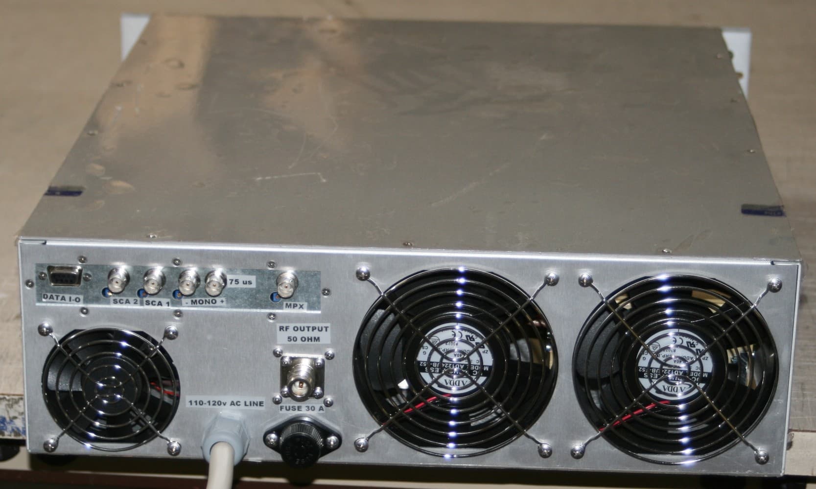
Click to zoom
Application Details
- Equipment Class
- TBC - Licensed Broadcast Station Transmitter
- Date of Grant
- Nov 30, 2011
- Application Purpose
- Original Equipment
- Date of Application
- Nov 30, 2011
- Equipment Note
- FM TRANSMITTER
- Frequency Range
- 88.00000000 - 108.00000000
- Company
- NiCOM USA
- Country
- United States
Documents & Files
Document Text
Text extracted from the exhibit documents filed with the FCC. Open a document above to read the original.
Block Diagram
VCO AUDIO INPUT RF DRIVER RF AMPLIFIER PLL LIMITER TCXO 12.8 MHz LPF DIRECTIONAL COUPLER POWER SUPPLY SIGNAL INTERFACE MICROCONTROLLER DISPLAY NICOM MPX MONO SCA ADJ RS232 VDCVAC RF OUTPUT MHz 98.000 Mod. NT 500 1.0 FUNCTIONAL SCHEMATIC B 11Friday, October 24, 2003 Title Size Document Number Rev Date:Sheetof N COM
External Photos
APPLICANT: NICOM USA INC. FCC ID: RMYNT500FP09 IC: 4788A-NT500 MODEL: NT500
Internal Photos
APPLICANT: NICOM USA INC. FCC ID: RMYNT500FP09 IC: 4788A-NT500 MODEL: NT500 AMP 600 BOARD AMP 600 BOARD – REAR VIEW MOTHER BOARD – TOP VIEW – WITH SHIELDS MOTHER BOARD – TOP VIEW – SHIELDS REMOVED MOTHER BOARD- REAR VIEW FRONT PUSH BUTTON – TOP VIEW FRONT PUSH BUTTON – REAR VIEW LOW PASS FILTER – FRONT VIEW LOW FILTER PASS – REAR VIEW LP500 – TOP VIEW LP500 – BOTTOM VIEW RF PALLET TOP VIEW OPEN TOP CHASSIS VIEW CHASSIS VIEW
Operational Description
NT-500 FM TRANSMITTER CIRCUIT DESCRIPTION The NT500 is a solid state FM transmitter using MOSFET power devices as the active radio frequeney elements. The equipment is composed by 1 RF amplifier modules mod. AMP600 which is matched for input/output impedance of 50 ohm. A drive power of 5W is required at the input to delivery nominal output power by the ESVA mother board. The signal is fed to a low-pass filter in order to reduce the unwanted harmonics to a insignificant level. The output of the filter includes directional coupler with the sensor mounted in a printed circuit. This sensor measures the incident and reflected RF power level and it is flat in the whole band within 5 % tolerance. The equipment features a circuits based upon a microprocessor which monitors the operation of the RF circuits so as to maximize operational lífe and minimize down-time and operator intervention. A front panel LCD shows in real time the essential operation parameters: RF OUTPUT POWER RF REFLECTED POWER OPERATING FREQUENCY MODULATION All data are available to a DB9 connector placed on the rear panel in order to remote control the transmitter. A particular fold-back circuit ensures the output power is reduced in relation to the reflected power from the load, in order to keep the active elements Mos-Fet type to a safe level. Also a temperature sensor is present in the RF power module in order to avoid overheating. This sensor is connected to the interlock in order to shut down the RF in case of high temperature. The RF modules' power supply circuit employs one very high efficiency 115-240 VAC AC/DC. The power supply is protected against accidental short circuits and, importantly, features a rapid power shut-down system which can save the delicate MOSFET devices from damage which they would otherwise incur even after short periods of overload.
Parts List/Tune Up Info
NICOM Rif.ValueRemarksDescriptionCode C122MF16VSMD Aluminium Electrolytic Capacitor C222MF16VSMD Aluminium Electrolytic Capacitor C31nFSMD Multilayer Ceramic Capacitor C41nFSMD Multilayer Ceramic Capacitor C51nFSMD Multilayer Ceramic Capacitor C61nFSMD Multilayer Ceramic Capacitor C71nFSMD Multilayer Ceramic Capacitor C81nFSMD Multilayer Ceramic Capacitor C91nFSMD Multilayer Ceramic Capacitor C101nFSMD Multilayer Ceramic Capacitor C111nFSMD Multilayer Ceramic Capacitor C121nFSMD Multilayer Ceramic Capacitor C131nFSMD Multilayer Ceramic Capacitor C141nFSMD Multilayer Ceramic Capacitor C1510MF35VSMD Aluminium Electrolytic Capacitor C1639pFSMD Multilayer Ceramic Capacitor C1739pFSMD Multilayer Ceramic Capacitor C181nFSMD Multilayer Ceramic Capacitor C191nFSMD Multilayer Ceramic Capacitor C2039pFSMD Multilayer Ceramic Capacitor C2139pFSMD Multilayer Ceramic Capacitor C221nFSMD Multilayer Ceramic Capacitor C231nFSMD Multilayer Ceramic Capacitor C241nFSMD Multilayer Ceramic Capacitor C251nFSMD Multilayer Ceramic Capacitor C2660pFTrimmer Polyethylene Film Capacitor C2710pFSMD Multilayer Ceramic Capacitor C2822pFSMD Multilayer Ceramic Capacitor C29270pFSMD Multilayer Ceramic Capacitor C30100MF16VSMD Aluminium Electrolytic Capacitor C311000MF25VAluminium Electrolytic Capacitor C32270pFSMD Multilayer Ceramic Capacitor C33270pFSMD Multilayer Ceramic Capacitor C3410MF35VAluminium Electrolytic Capacitor C35470MF35VAluminium Electrolytic Capacitor C36470MF35VAluminium Electrolytic Capacitor C372.2MF50VSMD Aluminium Electrolytic Capacitor C3810MF35VSMD Aluminium Electrolytic Capacitor C3910pFSMD Multilayer Ceramic Capacitor C404.7nFPolyester Capacitor C41100MF25VSMD Aluminium Electrolytic Capacitor C426.8nFPolyester Capacitor C43100MF25VSMD Aluminium Electrolytic Capacitor C4447pFSMD Multilayer Ceramic Capacitor C4547pFSMD Multilayer Ceramic Capacitor C4610MF35VSMD Aluminium Electrolytic Capacitor C470.1MFSMD Multilayer Ceramic Capacitor C4833pFSMD Multilayer Ceramic Capacitor C4933pFSMD Multilayer Ceramic Capacitor Part List Schematic : ESVA-1D NICOM Rif.ValueRemarksDescriptionCode C5022MF16VSMD Aluminium Electrolytic Capacitor C51100MF25VSMD Aluminium Electrolytic Capacitor C520.1MFSMD Multilayer Ceramic Capacitor C530.1MFSMD Multilayer Ceramic Capacitor C541MF / 16VSMD Aluminium Electrolytic Capacitor C550.1MFSMD Multilayer Ceramic Capacitor C561MF16VSMD Aluminium Electrolytic Capacitor C571MF16VSMD Aluminium Electrolytic Capacitor C581MF16VSMD Aluminium Electrolytic Capacitor C591MF16VSMD Aluminium Electrolytic Capacitor C601000MF35VAluminium Electrolytic Capacitor C6110MF35VSMD Aluminium Electrolytic Capacitor C6210MF35VSMD Aluminium Electrolytic Capacitor C631000MF16VAluminium Electrolytic Capacitor C6447MF16VSMD Aluminium Electrolytic Capacitor C6547MF16VSMD Aluminium Electrolytic Capacitor C660.1MFSMD Multilayer Ceramic Capacitor C670.1MFSMD Multilayer Ceramic Capacitor C680.1MFSMD Multilayer Ceramic Capacitor C690.1MFSMD Multilayer Ceramic Capacitor C7022MF16VSMD Aluminium Electrolytic Capacitor C710.1MFSMD Multilayer Ceramic Capacitor C720.1MFSMD Multilayer Ceramic Capacitor C7322MF16VSMD Aluminium Electrolytic Capacitor C740.1MFSMD Multilayer Ceramic Capacitor C750.1MFSMD Multilayer Ceramic Capacitor C7647MF35VAluminium Electrolytic Capacitor C770.1MFSMD Multilayer Ceramic Capacitor C7810nFSMD Multilayer Ceramic Capacitor C79220MF35VAluminium Electrolytic Capacitor C80220MF35VAluminium Electrolytic Capacitor C8147MF16VSMD Aluminium Electrolytic Capacitor C820.1MFSMD Multilayer Ceramic Capacitor C830.1MFSMD Multilayer Ceramic Capacitor C8447MF16VSMD Aluminium Electrolytic Capacitor C850.1MFSMD Multilayer Ceramic Capacitor C8622MF16VSMD Aluminium Electrolytic Capacitor C870.1MFSMD Multilayer Ceramic Capacitor C880.1MFSMD Multilayer Ceramic Capacitor C8922MF16VSMD Aluminium Electrolytic Capacitor C900.1MFSMD Multilayer Ceramic Capacitor C9110MF 35VSMD Aluminium Electrolytic Capacitor C920.1MFSMD Multilayer Ceramic Capacitor C93100MF25VAluminium Electrolytic Capacitor C9410MF 35VAluminium Electrolytic Capacitor C950.1MFSMD Multilayer Ceramic Capacitor C962.2MF 50VSMD Aluminium Electrolytic Capacitor C972.2MF 50VSMD Aluminium Electrolytic Capacitor C982.2MF 50VSMD Aluminium Electrolytic Capacitor C994.7MF35VSMD Aluminium Electrolytic Capacitor C1002.2MF 50VSMD Aluminium Electrolytic Capacitor C1010.1MFSMD Multilayer Ceramic Capacitor NICOM Rif.ValueRemarksDescriptionCode C10210MF 35VSMD Aluminium Electrolytic Capacitor C1032.2MF 50VSMD Aluminium Electrolytic Capacitor C10410MF 35VSMD Aluminium Electrolytic Capacitor C1050.1MFSMD Multilayer Ceramic Capacitor C1061000MF16VAluminium Electrolytic Capacitor C1072.2MF 50VSMD Aluminium Electrolytic Capacitor C1082.2MF 50VSMD Aluminium Electrolytic Capacitor C1091000MF16VAluminium Electrolytic Capacitor C1100.1MFSMD Multilayer Ceramic Capacitor C11110MF 35VSMD Aluminium Electrolytic Capacitor C1120.1MFSMD Multilayer Ceramic Capacitor C1130.1MFSMD Multilayer Ceramic Capacitor C11410MF 35VSMD Aluminium Electrolytic Capacitor C1150.1MFSMD Multilayer Ceramic Capacitor C116100pFSMD Multilayer Ceramic Capacitor C1173.3pFSMD Multilayer Ceramic Capacitor C1182.2MF 50VSMD Aluminium Electrolytic Capacitor C1193.3pFSMD Multilayer Ceramic Capacitor C120100pFSMD Multilayer Ceramic Capacitor C12147MF16VSMD Aluminium Electrolytic Capacitor C122100pFSMD Multilayer Ceramic Capacitor C12322pFSMD Multilayer Ceramic Capacitor C12410MF 35VSMD Multilayer Ceramic Capacitor C12522MF16VSMD Aluminium Electrolytic Capacitor C1260.1MFSMD Multilayer Ceramic Capacitor C1270.1MFSMD Multilayer Ceramic Capacitor C12822MF16VSMD Aluminium Electrolytic Capacitor C1291nFSMD Multilayer Ceramic Capacitor C1302.2MF 50VSMD Aluminium Electrolytic Capacitor C131470MF16VAluminium Electrolytic Capacitor C13222MF16VSMD Aluminium Electrolytic Capacitor C1330.1MFSMD Multilayer Ceramic Capacitor C134470MF16VAluminium Electrolytic Capacitor C1351000MF16VAluminium Electrolytic Capacitor C13647MF16VSMD Al…
Text truncated - open the document above for the full version.
Parts List/Tune Up Info
NT 500 PROGRAMMING Connect a 50 ohm load or 50 ohm antenna to the RF output, connect the equipment into a mains supply (120 or 240 VAC). The equipment is factory pre-set to 50 W. Switch ON the power and the yellow V POWER LED will light. The Display will show: SETTING PROGRAM WAIT After 3 seconds the green PLL LOCK led will light and the Display will show an increasing bar. After a further 5 seconds the green ENABLE will light and there will be output power. At this point the Display will show the next parameter: • Level Modulation (MOD > • Forward Power (FRW 50.0W); • Reflected Power (RFL 0.4W). SETTING PROGRAM MOD > PW 50W PR 0.4W The default frequency is 98.000 MHz. To display the frequency push the SETTING key. In order to display the parameter push the SELECT key. Display Password The Password mode is factory set to enable, and is not possible change this setting. The default password is 1 2 3 . The way for changing the password is the following: 5 • Press the PROGRAM key for 3 seconds; • Press the PROGRAM key to move the underscore character position at the required digit, and press the SETTING key to confirm the digit. Repeat the same for the two remaining digits. • If the password is correct press the SETTING key to confirm, otherwise press the PROGRAM key to select again. If the password is not correct an error is displayed: After a few seconds the display will show the parameters again. PASSWORD 0 1 2 3 4 5 6 7 8 9 PROGRAM SETTING * PROGRAM PASSWORD 0 1 2 3 4 5 6 7 8 9 SETTING * * * PROGRAM PASSWORD 0 1 2 3 4 5 6 7 8 9 SETTING PROGRAM CONFIRM (Y/N) ? N=SEL. Y=SET. SETTING PROGRAM ERROR PASSWORD SETTING 6 When the password is correct, the display will show: PROGRAM NEW PASS . = SET. NEW FREQ . = PRG . SETTING To change the password press the SETTING key. To change the frequency press the PROGRAM key. • For changing the password proceed with the same method for the required password: The confirmation password will be required. If the password is correct the display will show: If the confirmation password is wrong the display will show: NEW PASSWORD 0 1 2 3 4 5 6 7 8 9 PROGRAM SETTING CONFIRMATION 0 1 2 3 4 5 6 7 8 9 PROGRAM SETTING STORED NEW PASSWORD PROGRAM SETTING PROGRAM ERROR CONFIRMATION SETTING 7 IMPORTANT NOTE ! BE CAREFUL ! Once the password is set, it must be remembered, otherwise neither the frequency nor the password can be reset and the unit will have to be returned to Nicom for resetting. Display Change of Frequency. • Press the PROGRAM key for 3 seconds and enter the correct password. At this point press again the SELECT key: • Press the PROGRAM key to change the desired digit and press the SETTING key to confirm it. NEW PASS . = SET. NEW FREQ . = PRG . PROGRAM SETTING FREQUENCY ? MHz 1 03.900 PROGRAM SETTING The underscore character indicates which digit can be change. To move the underscore character hit the PROGRAM key. When the new frequency is chosen, then press the SETTING key confirm it. After a “WAIT CYCLE”, the display will show the parameters: MOD > PW 1000W PR 0.4W PROGRAM SETTING After 7 minutes the display light will switch off and the display will show: NICOM MHz 103.900 PROGRAM 8 SETTING
Schematics
TX GND RX Mod. ESVA-1D 1.0 Mather Board ESVA-1D C 11Tuesday, October 12, 2004 Title SizeDocument NumberRev Date:Sheet of NCOM RF DRIVER RF INPUT RF OUTPUT GND RF OUTPUT GND RF INPUT +15V GND DRIVER OFF V-ADJ Microcontroller VU Meter ENABLE RX RS232 TX RS232 PLL LOCK SW2 DATA RF ON/OFF GND CLOCK Temperature Reflected PW SW1 Forward PW +5V Protection & Meter +5V +15V GND -15V FORWARD POWER REFLECT POWER V. GATE RF FWD METER RF RFL METER ADJ-A ADJ-B ADJ-C VADJ LED RF DB9_FWD_PW DB9_RFL_PW Interlock +24V DRIVER OFF VCO +15V GND V-VCO BF IN RF OUT GND RF OUT GND BF IN RF PLL GND RF PLL PLL +15V GND V-VCO +5V ENABLE GND DATA DATA CLOCK GND RF IN LED LOCK RF IN PLL LOCK Power Supply GND +15V +24V -15V VB VD +5V VA VC -5V Audio BF OUT VC VB GND VA VD GND BF OUT VU METER MONO + GND MONO MONO - SCA 1 GND SCA 1 SCA 2 SCA 3 MPX GND SCA 2 GND SCA 3 GND MPX +15V -15V -5V INTERLOCK LOCK LOCK CLOCK CLOCK ENABLE TEMP. TEMP. DATA DATA ENABLE INTERLOCK -5V GND ADJ-C GND LED PW LED LOCK LED LOCK SW2 LED RF ADJ-B ADJ-A SW1 SW2 SW1 LED LOCK SW1 SW2 DB9_RFL DB9_RFL INTERLOCK +24V ADJ-A +24V LED RF +5V FWD PWV-ADJ -5V IN FWD PW +24 V ADJ-C ADJ-B +5V ADJ-A DB9_FWD IN RFL PW IN FWD PW ADJ-C +24V DB9_FWD V-GATE FWD PW V-ADJ RFL PW V-GATE +5V +5V ADJ-B LED RF +5V INTERLOCK IN RFL PW RFL PW +5V +5V +5V VD VC +15V +15 V VU METER VU METER -15V -15V VC GND VD GND VB +15 V VA +15 V VA +15V VB GND -15V GND GND GND GND ADJ-A ADJ-B ADJ-C GND LED RF GND LED LOCK LED PW SW2 SW1 GND V-ADJ +15V LED PW +15 V J5 STEREO_CODER 1 2 3 L9 22uH J11 XLR 21 3 4 + C1 22MF / 16V C20 39pF C17 39pF C21 39pF J2 SMB D1 LL4148 J19 PUSH 1 2 3 C19 1nF C4 1nF L1 22uH TERM7 GND C3 1nF L822uH C13 1nF C14 1nF L6 22uH C18 1nF 1 10 J3 DJ2x5 TERM6 V-ADJ C9 1nF 1 10 J13 DB9 C10 1nF J20 RJ45 4 5 6 7 8 3 2 1 R192 1K5 J33 N + C2 22MF / 16V + C15 10MF / 35V C16 39pF C5 1nF C6 1nF J31E C8 1nF C7 1nF TERM2 -5V TERM1 +5V L1022uH C22 1nF L3 22uH L2 22uH R410K C23 1nF J12 DB9_AUX 1 2 3 R3 10K D2LL4148 J4 BNC 1 2 R2 2K2 1 J7 DJ3 R1 2K2 TERM3 FWD PWR TERM4 RFL PWR TERM5 V. GATE R193 2K2 SW1 DB9 MONITOR 1 2 3 4 8 7 6 5 L7 22uH C12 1nF C11 1nF L5 22uH J6 BNC 1 2 L4 22uH J8 BNC 1 2 J9 BNC 1 2 J34 15V C24 1nF C25 1nF L1122uH J10 BNC 1 2 J1 POWER J32A CMRR LIMITER STEREO 75uS 50uS MONO MODULATION Mod. ESVA-1D 1.0 Audio Output C 11Tuesday, October 12, 2004 Title SizeDocument NumberRev Date:Sheet of NCOM VC VD VA VB +15V +15V-15V VA VC VB VD -15V +15V -15V R18 1K2 R19 3K9 R38 100 J14 DJ3 + C30 100MF / 25V R30 560K + C37 2.2MF / 50V R179 20K R40 1K2 D6 3V3 R32 100K + - U2B LM358 5 6 7 R39 10K R48 10K + C41 100MF / 25V + C43 100MF / 25V R37 4K7 R47 4K7 R5 27K R51 4K7 + - U3A LF353 3 2 1 8 4 R41 1K2 R52 10K R7 12K C45 47pF R25 220K R26 100K + C34 10MF / 35V R24 33 R12 1K R8 47K R44 10K R22 1K R27 1K C42 6.8nF J15 DJ3 C40 4.7nF + C31 1000MF / 25V C26 60pF R20 1K FILT1 FILTER 19KHz 123456 78 R17 3K9 R15 1K2 D4 BAT43 R46 3K9 D3 BAT43 + - U3B LF353 5 6 7 R45 3K9 R36 10K R9 5K R42 10K D5 LL4148 R35 560K R6 47K R49 2K2 C44 47pF + - U1A OP275 3 2 1 + - U1B OP275 5 6 7 8 4 R50 10K R16 200 R43 5K C27 10pF R10 27K R21 12K R14 12K R28 4K7 R23 12K C29 270pF C33 270pF C32 270pF + C35 470MF / 25V R29 10K + C36 470MF / 25V R34 NC D7 LL4148 D8 LL4148 + C38 10MF / 35V R31 100K R13 10K C28 22pF R11 47K C39 10pF + - U2A LM358 3 2 1 8 4 R33 33 BF OUT VC VB GND VA VD GND BF OUT VU METER MONO + GND MONO MONO - SCA 1 GND SCA 1 SCA 2 SCA 3 MPX GND SCA 2 GND SCA 3 GND MPX +15V -15V Mod. ESVA-1D 1.0 Microcontroller B 11Tuesday, October 12, 2004 Title SizeDocument NumberRev Date:Sheetof NCOM PLL_DTA CH3 PLL_EN EN RW ADC_EN RX SW1 TXD RXD SW1 RW TXD CH0 RS SW1RXD PLL_LOCK PLL_CLK SDTA SETUP RS EN CH2 PLL_EN RF_ONOFF PLL_LOCK SCLK ADC_EN SETUP SDTA CH1 PROG. TX RF_ONOFF SCLK LAMP D1 LAMP D4 D3D1 D5 D0D6D2D4 D7 D[0:7] D2D3D6 D1 D7D5D0 D2 SW2 D0 D7 SW2 D4 D3 D5 D6 SW2 PLL_CLK PLL_DTA +5V +5V +5V +5V +5V +5V +5V LCD1DISPLAY V20350 12345678910111213141516171819202122232425262728293031323334 GNDVCCV0RSRWENDB0DB1DB2DB3DB4DB5DB6DB7LED -LED +NC_GND_VCC_V0_RS_RW_EN_DB0_DB1_DB2_DB3_DB4_DB5_DB6_DB7_LED-_LED+_NC JP1 J16 DJ2 Q1 BC327 + C50 22MF / 16V U6T89C51RD2 2 3 4 5 6 7 8 9 10 11 13 14 15 16 17 18 19 20 21 24 25 26 27 28 29 30 31 32 33 36 37 38 39 40 41 42 43 35 22 231 12 34 44 P1.0 P1.1 P1.2 P1.3 P1.4 P1.5 P1.6 P1.7 RST RxD TxD INT0 INT1 T0 T1 WR RT XTAL2 XTAL1 P2.0 P2.1 P2.2 P2.3 P2.4 P2.5 P2.6 P2.7 PSEN ALE P0.7 P0.6 P0.5 P0.4 P0.3 P0.2 P0.1 P0.0 EA GND CA B D VCC U7MAX232 1 2 3 4 56 7 8 16 15 14 1312 11 10 9 C1+ V+ C1- C2+ C2-V- T2 OUT R2 IN VCC GND T1 OUT R1 INR1 OUT T1 IN T2 IN R2 OUT U4ADC0834 3 4 5 6 1 9 8 7 11 2 12 13 10 14 CH0 CH1 CH2 CH3 Vref OUT Vref IN AGND DGND SARS CS CLK DI DO VCC C R53 10K 1 23456789 C49 33pF C48 33pF Y1 11.0592MHz R60 NC C52 0.1MF R59 NC R62 10K C55 0.1MF C47 0.1MF + C46 10MF / 35V J17 DJ2 + C51 100MF / 25V R64 10K + C591MF / 16V R5510K R65 1K2 R61 NC R5810K R5610K R5710K + C54 1MF / 16V C53 0.1MF + C561MF / 16V + C581MF / 16V + C571MF / 16V R66 6k8 R72 6k8 R70 6k8 R69 6k8 R68 6k8 R67 6k8 R71 6k8 R63 1K5 R54 1K D9LL4148 U5 MAX810L 1 2 3 GND RST VCC VU Meter ENABLE RX RS232 TX RS232 PLL LOCK SW2 DATA RF ON/OFF GND CLOCK Temperature Reflected PW SW1 Forward PW +5V Mod. ESVA-1D 1.0 Power Supply A3 11Tuesday, October 12, 2004 Title SizeDocument NumberRev Date:Sheetof NCOM + C81 47MF / 16V U8LM78S15/TO 1 2 3 IN GND OUT Q14 TIP41C + C64 47MF / 16V Q15 TIP42C U11MC79M05CDT 2 1 3 IN GND OUT + C80 220MF / 35V + C61 10MF / 35V C69 0.1MF + C65 47MF / 16V C68 0.1MF C74 0.1MF C75 0.1MF + C73 22MF / 16V R76 33 R73 1K2 + C89 22MF / 16V C90 0.1MF C88 0.1MF R79 33 U20E 40106 1110 U20D 40106 98 U20C 40106 56 U20B 40106 34 C85 0.1MF + C86 22MF / 16V C87 0.1MF R78 33 D10 LED D12 MRA4007 D13 MRA4007 C71 0.1MF R75 33 D15 LED + C70 22MF / 16V R80 1K2 C72 0.1MF D33 MRA4007 U10LM7915 2 1 3 IN GND OUT + C161 47MF / 35V + C60 1000MF / 35V D34 MRA4007 + C162 47MF / 35V + C163 47MF / 35V + C62 10MF / 35V C67 0.1MF + C164 47MF / 35V + C76 47MF / 35V C165 0.1MF C66 0.1MF U9MC78M05CDT 1 2 3 IN GND OUT + C79 …
Text truncated - open the document above for the full version.
Test Report
FCC PART 73.801 AND IC BETS-6 LOW POWER FM BROADCAST STATIONS (LPFM) TEST REPORT APPLICANT NiCOM USA, INC. 1690 CACTUS ROAD SAN DIEGO, CA 92154 FCC ID RMYNT500FP09 IC CERTIFICATION 4788A-NT500 MODEL NUMBER NT500 PRODUCT DESCRIPTION 500 W FM TRANSMITTER DATE SAMPLE RECEIVED 10/3/11 DATE TESTED 10/3/11 TESTED BY Joe Scoglio APPROVED BY Mario de Aranzeta TIMCO REPORT NO. 2296AT11TestReport.doc TEST RESULTS PASS FAIL THE ATTACHED REPORT SHALL NOT BE REPRODUCED EXCEPT IN FULL WITHOUT THE WRITTEN APPROVAL OF TIMCO ENGINEERING, INC. 849 NW STATE ROAD 45 NEWBERRY, FL 32669 USA PH: 888.472.2424 OR 352.472.5500 FAX: 352.472.2030 EMAIL: [email protected] HTTP: //WWW.TIMCOENGR.COM Certificate # 0955-01 Applicant: NICOM USA, INC. FCC ID: RMYNT500FP09 IC: 4788A-NT500 MODEL #: NT500 Report: Z:\N\Nicom\2296AT11\Extra2296AT11\2296AT11TestReport.doc Page 2 of 19 TABLE OF CONTENTS GENERAL REMARKS ................................................................................................. 3 GENERAL INFORMATION .......................................................................................... 4 EQUIPMENT LIST ...................................................................................................... 5 TEST PROCEDURE ................................................................................................... 6 RF POWER OUTPUT .................................................................................................. 7 MODULATION CHARACTERISTICS ............................................................................ 8 OTHER MODULATION CHARACTERISTICS ............................................................. 10 OCCUPIED BANDWIDTH ......................................................................................... 11 SPURIOUS EMISSIONS AT ANTENNA TERMINALS (CONDUCTED) ........................... 15 FIELD STRENGTH OF SPURIOUS EMISSIONS ......................................................... 17 FREQUENCY STABILITY .......................................................................................... 19 Applicant: NICOM USA, INC. FCC ID: RMYNT500FP09 IC: 4788A-NT500 MODEL #: NT500 Report: Z:\N\Nicom\2296AT11\Extra2296AT11\2296AT11TestReport.doc Page 3 of 19 GENERAL REMARKS The attached report shall not be reproduced except in full without the written permission of Timco Engineering Inc. Summary The device under test does: fulfill the general approval requirements as identified in this test report not fulfill the general approval requirements as identified in this test report Attestations This equipment has been tested in accordance with the standards identified in this test report. To the best of my knowledge and belief, these tests were performed using the measurement procedures described in this report. All instrumentation and accessories used to test products for compliance to the indicated standards are calibrated regularly in accordance with ISO 17025 requirements. Testing Certificate # 0955-01 I attest that the necessary measurements were made, under my supervision, at: Timco Engineering Inc. 849 NW State Road 45 Newberry, Fl 32669 Authorized Signatory Name: Mario de Aranzeta C.E.T. Compliance Engineer/ Lab. Supervisor Date: 10/3/11 Applicant: NICOM USA, INC. FCC ID: RMYNT500FP09 IC: 4788A-NT500 MODEL #: NT500 Report: Z:\N\Nicom\2296AT11\Extra2296AT11\2296AT11TestReport.doc Page 4 of 19 GENERAL INFORMATION DUT Specification DUT Description 500W FM TRANSMITTER FCC ID RMYNT500FP09 Model Number NT500 Operating Frequency 88.1 to 107.9 MHz Type of Emission 200K0F3E Modulation FM Output power 500 Watts DUT Power Source 110–120Vac/50– 60Hz DC Power 12V Battery Operated Exclusively Test Item Prototype Pre-Production Production Type of Equipment Fixed Mobile Portable Test Conditions temperature 26ºC relative humidity 50%. Modification to the DUT None Test Exercise The DUT was placed in continuous transmit mode. Applicable Standards ANSI/TIA 603-C:2004, FCC CFR 47 Part 73 BETS-6 Test Facility Timco Engineering Inc. at 849 NW State Road 45 Newberry, FL 32669 USA. Applicant: NICOM USA, INC. FCC ID: RMYNT500FP09 IC: 4788A-NT500 MODEL #: NT500 Report: Z:\N\Nicom\2296AT11\Extra2296AT11\2296AT11TestReport.doc Page 5 of 19 EQUIPMENT LIST Device Manufacturer Model Serial Number Cal/Char Date Due Date 3-Meter Semi- Anechoic Chamber Panashield N/A N/A Listed 5/10/10 5/10/12 AC Voltmeter HP 400FL 2213A14499 CAL 6/12/11 6/12/13 Antenna: Active Loop ETS-Lindgren 6502 00062529 CAL 9/23/10 9/23/12 Antenna: Passive Loop EMC Test Systems EMCO 6512 9706-1211 CAL. 10/1/09 10/2/11 Frequency Counter HP 5385A 2730A03025 CAL 8/17/11 8/17/13 Hygro- Thermometer Extech 445703 0602 CAL 6/15/11 6/15/13 Modulation Analyzer HP 8901A 3435A06868 CAL 7/18/11 7/18/13 Digital Multimeter Fluke FLUKE-77 35053830 CAL 9/9/11 9/9/13 Analyzer Tan Tower Preamplifier HP 8449B-H02 3008A00372 CAL 11/21/09 11/21/11 Analyzer Tan Tower Quasi- Peak Adapter HP 85650A 3303A01690 CAL 11/22/09 11/22/11 Analyzer Tan Tower RF Preselector HP 85685A 3221A01400 CAL 11/21/09 11/21/11 Analyzer Tan Tower Spectrum Analyzer HP 8566B Opt 462 3138A07786 3144A20661 CAL 11/24/09 11/24/11 Temperature Chamber Tenney Engineering TTRC 11717-7 CHAR 4/25/10 4/25/12 Antenna ETS 3117 41534 9/22/2010 9/22/2012 Antenna Electro metrics LPA-25 1122 5/04/2011 5/04/2013 Antenna Electro metrics BIA-25 1171 1/15/2010 1/15/2012 Applicant: NICOM USA, INC. FCC ID: RMYNT500FP09 IC: 4788A-NT500 MODEL #: NT500 Report: Z:\N\Nicom\2296AT11\Extra2296AT11\2296AT11TestReport.doc Page 6 of 19 TEST PROCEDURE Power Line Conducted Interference: The procedure used was ANSI/TIA 603-C:2004, using a 50uH LISN. Both lines were observed with the UUT transmitting. The bandwidth of the spectrum analyzer was 10 kHz with an appropriate sweep speed. Bandwidth 20 dB: The measurements were made with the spectrum analyzer's resolution bandwidth (RBW) = 1 MHz and the video bandwidth (VBW) = 3 MHz and the span set as shown on plot. Power Output: The RF power output was mea…
Text truncated - open the document above for the full version.
Test Setup Photos
APPLICANT: NICOM USA INC. FCC ID: RMYNT500FP09 IC: 4788A-NT500 MODEL: NT500 TEST SET UP PHOTOS
Contact Information
Applicant
Dario Piagentini(Vice President)
Test Firm
Timco Engineering, Inc.Bruno Clavier
Technical Specifications
| # | Rule Parts | Frequency Range | Power Output | Emission | Tolerance |
|---|---|---|---|---|---|
| 1 | 73 | 88 MHz - 108 MHz | 500 W | 200KF3E | 1.7300000000 ppm |
Other Applications from NiCOM USA
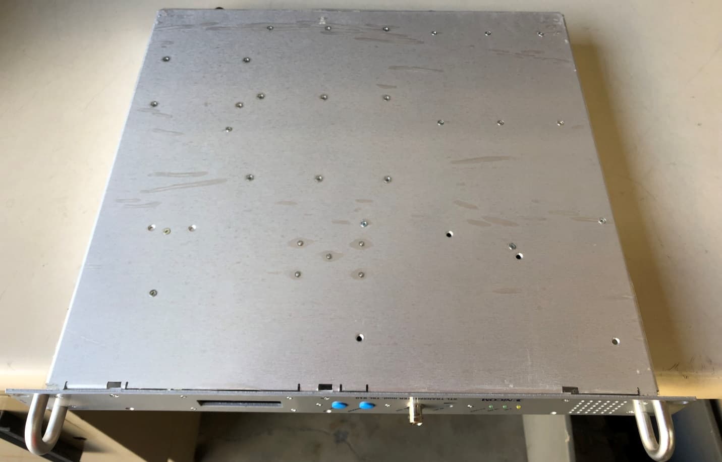
RMYTSL910
Mar 15, 2020STL TRANSMITTER
Equipment Class
TBC - Licensed Broadcast Station Transmitter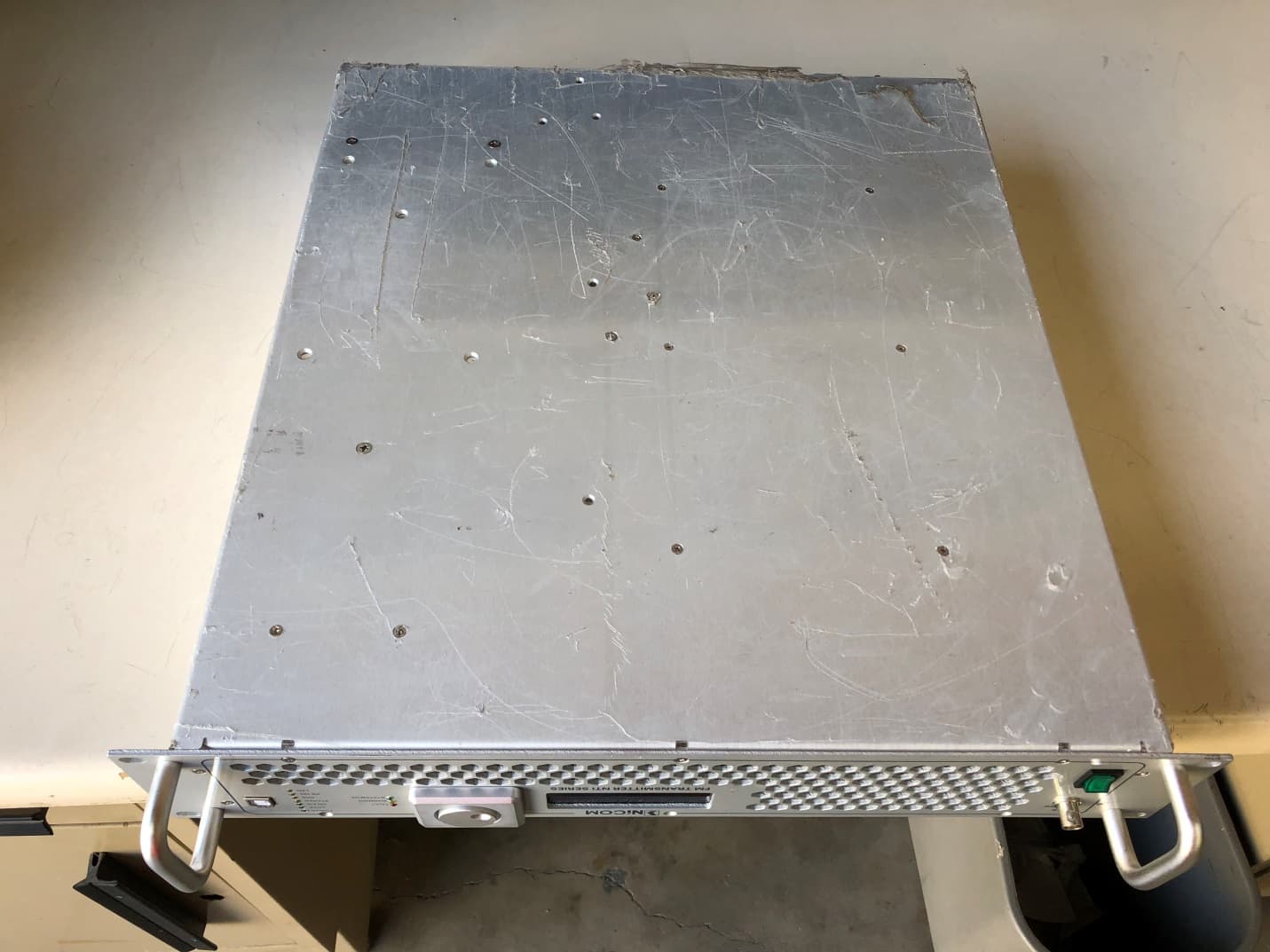
RMYNTI600
Mar 12, 2020FM BROADCAST TRANSMITTER
Equipment Class
TBC - Licensed Broadcast Station Transmitter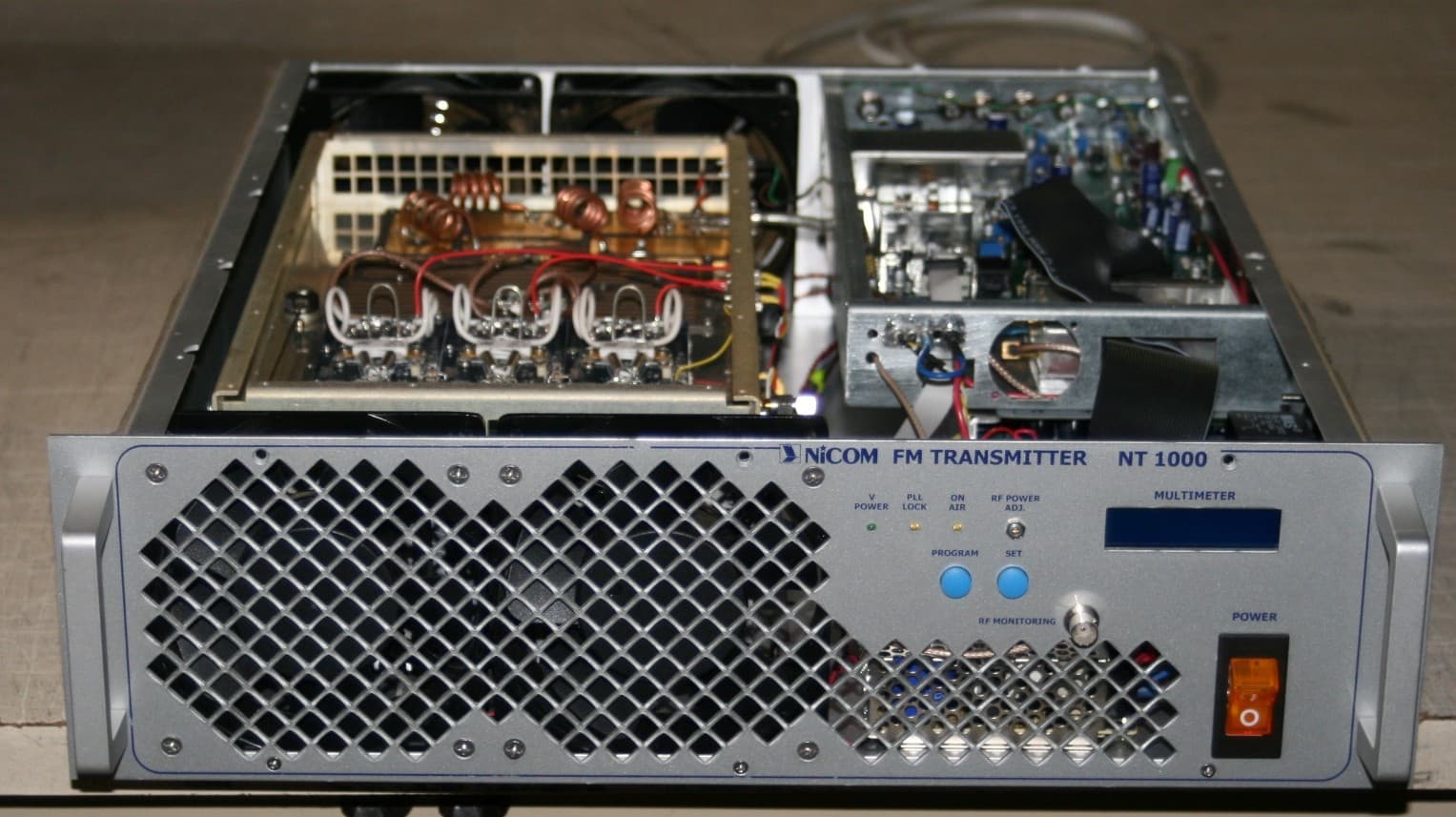
RMYNT1000FP09
Nov 30, 2011FM TRANSMITTER
Equipment Class
TBC - Licensed Broadcast Station Transmitter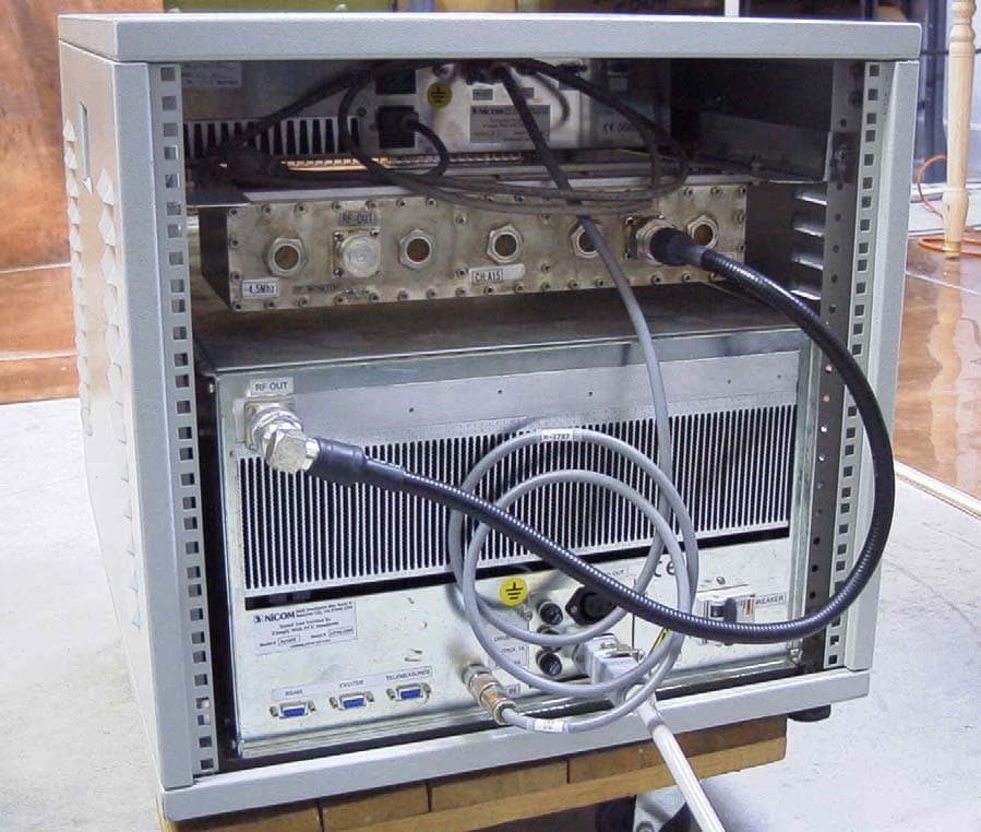
RMYAP1000FP06
Jul 30, 2007UHF TV AMPLIFIER
Equipment Class
TBC - Licensed Broadcast Station Transmitter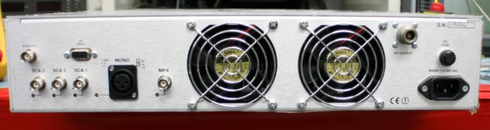
RMYNT350FP07
Jul 26, 2007350W TRANSMITTER
Equipment Class
TBC - Licensed Broadcast Station Transmitter