RO5IWAPINTERFACEAccess Point System
InnerWireless, Inc.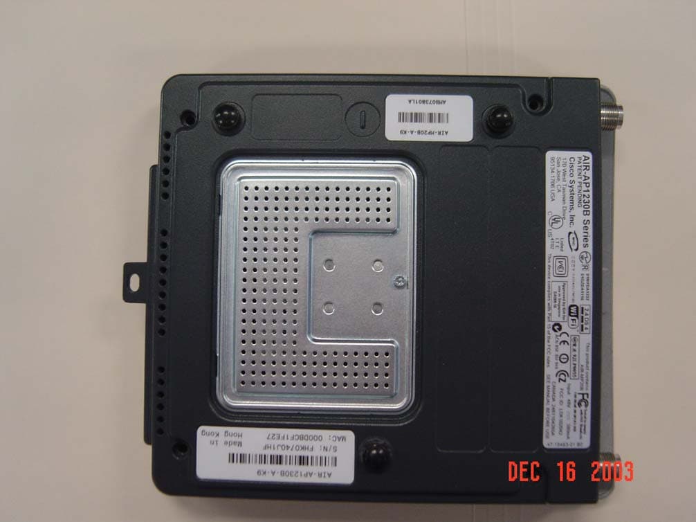
Click to zoom
Application Details
- Equipment Class
- DTS - Digital Transmission System
- Date of Grant
- Feb 29, 2004
- Application Purpose
- Original Equipment
- Date of Application
- Feb 29, 2004
- Equipment Note
- Access Point System
- Frequency Range
- 2412.00000000 - 2462.00000000
- Company
- InnerWireless, Inc.
- Country
- United States
Documents & Files
Document Text
Text extracted from the exhibit documents filed with the FCC. Open a document above to read the original.
Users Manual
InnerWireless, Inc. Richardson, Texas InnerWireless Access Point Interface COPYRIGHT© 2003 InnerWireless ALL RIGHTS RESERVED All information set forth in this document and all rights in and to intellectual property disclosed herein are the exclusive property of InnerWireless. No disclosure of this document and/or the information contained herein shall be made to any other person or organization without the prior written consent of InnerWireless. Table of Contents Table of Contents........................................................................................................- 2 - 1 FRONT CHAPTER...............................................................................................- 3 - 1.1 POLICY FOR INNERMOBILE ® SYSTEM WARRANTY AND SUPPORT SERVICES..............................................................................................................- 3 - 1.2 TO RETURN EQUIPMENT FOR REPAIR:...................................................- 4 - 1.3 CONVENTIONS............................................................................................- 4 - 1.4 RF EXPOSURE COMPLIANCE....................................................................- 4 - 1.5 PRECAUTIONS............................................................................................- 5 - 2 PURPOSE AND SCOPE.....................................................................................- 5 - 3 802.11 ACCESS POINT CONNECTION TO WDS SYSTEM..............................- 6 - - 2 - 1 FRONT CHAPTER 1.1 POLICY for InnerMobile ® System Warranty and Support Services 1.1.1 INNERMOBILE ® SYSTEM STANDARD WARRANTY InnerWireless, Inc. warrants, for a period of one (1) year beginning upon the sign off of the InnerWireless Acceptance Test Procedure (ATP) for the identified InnerMobile ® System provided herein, to be free from defects in materials and workmanship, and will operate and conform according to the product specifications. Warranty provided does not assure uninterrupted operation of the equipment, nor does it include any repairs necessitated by Customer’s, or third party’s, improper or unauthorized use or modification of the System. Customer accepts all responsibility for the physical security of the System. Warranty includes all parts and materials, with exceptions (see below), to meet the engineered specification contained in the contract. Customer will approve the engineered specifications per the InnerWireless acceptance and signoff procedure. InnerMobile ® Equipment included in warranty: In the event that service is disabled or degraded from it’s original design, InnerWireless warrants all original equipment installed as part of the InnerMobile ® System. The original equipment as it relates to the specific installation may include the following. • Coax cable required to deliver the RF signal through out each floor of the building • Jumper cables and connectors required to assemble the InnerMobile ® System • Access Point Interface (API) utilized as part of the InnerMobile ® System • Any antenna required to radiate the RF signal to the intended areas InnerWireless, Inc., at its sole discretion, will repair or replace any components of the InnerMobile ® System that are found to be faulty. Any replacements will be shipped from InnerWireless Inc. via next day delivery from the time the parts are available. InnerWireless will not maintain, or allow for the storage of spare components at the customer site. All warranty work shall be performed after notification by Customer that the system, or portion of the system, is inoperative, and Customer has followed the published procedures to troubleshoot and repair the failure without success. This warranty is expressly in lieu of any other warranties, express or implied, including any implied warranty of merchantability or warranty of fitness for a particular purpose, and of any other obligation or liability on the part of InnerWireless: InnerWireless neither assumes nor authorizes any other person to assume for it any liability in connection with its products. In no event shall InnerWireless be liable for any indirect, incidental, special or consequential damages arising out of the sale, manufacture or use of any of its products. In any event, the total liability of InnerWireless arising from any cause of action or claim whatsoever, whether (1) in contract, (2) in tort (including negligence, whether sole, joint, contributory, concurrent or otherwise), (3) under strict liability, (4) under any environmental or antipollution law or regulation, (5) connected with any toxic or hazardous substance or constituent, (6) arising out of any representation or instruction, or under any warranty, (7) or otherwise, arising out of, connected with, or resulting from the design, manufacture, sale, resale, delivery, repair, replacement or use of products or the furnishing of any service shall in no event exceed the price allocable to and paid to - 3 - InnerWireless for the individual unit of products or service or part thereof which gives rise to the cause of action or claim. 1.2 TO RETURN EQUIPMENT FOR REPAIR: • Be able to communicate to InnerWireless the nature of the problem with the equipment • Provide to InnerWireless your specific company name, ship to address, contact name and phone number. • Call the customer service center to set up appropriate return address, per the component being returned for repair. • InnerWireless return address: InnerWireless, Inc. Repair Services 1155 Kas Drive, Suite 200 Richardson, TX, 75081 1-866-472-9898 1.3 CONVENTIONS In this manual the following special formats are used: ! Warning WARNINGS CONTAIN INFORMATION REGARDING DANGEROUS FUNCTIONS. 1.4 RF EXPOSURE COMPLIANCE ! Warning TO COMPLY WITH FCC RF EXPOSURE COMPLIANCE REQUIREMENTS, ANTENNAS USED FOR THIS PRODUCT MUST BE FIXED MOUNTED ON INDOOR PERMANENT STRUCTURES, PROVIDING A SEPARATION DISTANCE OF AT LEAST 20 CM FROM ALL PERSONS DURING NORMAL OPERATION. - 4 - 1.5 PRECAUTIO…
Text truncated - open the document above for the full version.
Users Manual
360 Herndon Parkway Suite 1400 Herndon, VA 20170 http://www.rheintech.com Certification Report For: Cisco System Page 40 Document Number: 2001041 Revision 3 23 MANUAL C-1 Cisco Aironet AIR-MPI352 OL-XXXX-0X APPENDIXC Declarations of Conformity and Regulatory Information This appendix provides declarations of conformity and regulatory information for the Cisco Aironet AIR-MPI352. The following topics are covered in this section: •Manufacturers Federal Communication Commission Declaration of Conformity Statement, page C-2 •Industry of Canada Spectrum Management, page C-3 •Safety Information for the AIR-MPI352, page C-4 •European Community, Switzerland, Norway, Iceland, and Liechtenstein, page C-6 •Declaration of Conformity for RF Exposure, page C-8 Appendix C Declarations of Conformity and Regulatory Information Manufacturers Federal Communication Commission Declaration of Conformity Statement C-2 Cisco Aironet AIR-MPI352 OL-XXXX-0X Manufacturers Federal Communication Commission Declaration of Conformity Statement Models:AIR-MPI352 FCC Certification Number:LDK102042 Manufacturer:Cisco Systems, Inc. 170 West Tasman Drive San Jose, CA 95134-1706 USA This device complies with Part 15 rules. Operation is subject to the following two conditions: 1.This device may not cause harmful interference, and 2.This device must accept any interference received, including interference that may cause undesired operation. This equipment has been tested and found to comply with the limits of a Class B digital device, pursuant to Part 15 of the FCC Rules. These limits are designed to provide reasonable protection against harmful interference when the equipment is operated in a residential environment. This equipment generates, uses, and radiates radio frequency energy, and if not installed and used in accordance with the instructions, may cause harmful interference. However, there is no guarantee that interference will not occur. If this equipment does cause interference to radio or television reception, which can be determined by turning the equipment off and on, the user is encouraged to correct the interference by one of the following measures: •Reorient or relocate the receiving antenna. •Increase separation between the equipment and receiver. Tested To Comply With FCC Standards FOR HOME OR OFFICE USE C-3 Cisco Aironet AIR-MPI352 OL-XXXX-0X Appendix C Declarations of Conformity and Regulatory Information Industry of Canada Spectrum Management •Connect the equipment to an outlet on a circuit different from which the receiver is connected. •Consult the dealer or an experienced radio/TV technician. CautionThe Part 15 radio device operates on a non-interference basis with other devices operating at this frequency. Any changes or modification to said product not expressly approved by Cisco could void the user’s authority to operate this device. NoteThe following label must be affixed to the OEM product containing the Cisco Aironet AIR-MPI352 product: This device contains: FCC ID: LDK102042 CANADA: 246 1103 XXXXX Industry of Canada Spectrum Management Canadian Compliance Statement This Class B Digital apparatus meets all the requirements of the Canadian Interference-Causing Equipment Regulations. Cet appareil numerique de la classe B respecte les exigences du Reglement sur le material broilleur du Canada. This device complies with Class B Limits of Industry Canada. Operation is subject to the following two conditions: 1.This device may not cause harmful interference, and 2.This device must accept any interference received, including interference that may cause undesired operation. Appendix C Declarations of Conformity and Regulatory Information Safety Information for the AIR-MPI352 C-4 Cisco Aironet AIR-MPI352 OL-XXXX-0X The device is certified to the requirements of RSS-210 for 2.4-GHz spread spectrum devices. The use of this device in a system operating either partially or completely outdoors may require the user to obtain a license for the system according to the Canadian regulations. For further information, contact your local Industry Canada office. Safety Information for the AIR-MPI352 The Federal Communications Commission (FCC) with its action in ET Docket 96-8 has adopted a safety standard for human exposure to RF electromagnetic energy emitted by FCC certified equipment. Cisco Aironet Mini PCI product meets the uncontrolled environmental limits found in OET-65 and ANSI C95.1, 1991. Proper operation of this radio according to the instructions found in this manual and the hardware and software guides on the Cisco Aironet Series Wireless LAN Adapters CD will result in user exposure that is substantially below the FCC recommended limits. •Do not touch or move the antenna(s) while the unit is transmitting or receiving. •Do not hold any component containing a radio such that the antenna is very close to or touching any exposed parts of the body, especially the face or eyes, while transmitting. •Do not operate the radio or attempt to transmit data unless the antenna is connected; otherwise, the radio may be damaged. •Use in specific environments: –Do not operate a portable transmitter near unshielded blasting caps or in an explosive environment unless it is a type especially qualified for such use. –The use of wireless devices in hazardous locations is limited to the constraints posed by the safety directors of such environments. –The use of wireless devices on airplanes is governed by the Federal Aviation Administration (FAA). –The use of wireless devices in hospitals is restricted to the limits set forth by each hospital. C-5 Cisco Aironet AIR-MPI352 OL-XXXX-0X Appendix C Declarations of Conformity and Regulatory Information Safety Information for the AIR-MPI352 –In order to comply with FCC RF exposure limits, high gain antennas should be located at a minimum distance of 7.9 inches (20 cm) or more from the body of all persons when used in a mobile or fixed type application. WarningIn order to comply with RF …
Text truncated - open the document above for the full version.
Cover Letter(s)
Cisco Systems, Inc. 4125 Highlander Parkway Richfield, Ohio 44286 Phone: 330 523-2094 Fax: 330 523-2002 http://www.cisco.com Phone: (330) 523-2094 Fax: (330) 523-2002 E-Mail: [email protected] February 23, 2004 Federal Communications Commission Equipment Authorization Division, Application Processing Branch 7435 Oakland Mills Road Columbia, MD 21046 Re: FCC ID: RO5IWAPINTERFACE To Whom It May Concern: The following information is to be held confidential pursuant to 47 CFR Part 0 §0.457 and Section 552(b)(4) of the Freedom of Information Act, because the information provided is proprietary and contains trade secrets. If made public, the information might be used to the disadvantage of the Cisco Systems, Inc. in the market place. Block Diagram Schematic Diagrams Technical Description Best Regards, Jim Nicholson EMC Compliance Engineer
Cover Letter(s)
LETTER STATING The device, FCC ID: RO5IWAPINTERFACE, will only be sold as part of a complete system in the configurations that were tested and authorized. The complete system will include the following devices: • Access Point: Cisco System, Model Number: CISCO 1200, FCC ID: LDK102042 • Access Point Interface: InnerWireless, Inc., Model Number: 11001Q002, FCC ID: RO5IWAPINTERFACE • Reverse polarity TNC Male to standard N Male jumper cable: Access Point to Access Point Interface cable, minimum length: 4 feet (Attenuation: 0.045 dB/ft.), (ex: Pasternack Enterprises, LLC. Model Number: PE-35249-48) • Maximum antenna gain: 7.1 dBi (ex: PCB LPA: InnerWireless, Inc., Model Number: 00702L001) Yiuman Leung VP Product Management InnerWireless, Inc. Tel: 972-201-2533 Mobile: 972-333-1004 Fax: 972-479-9625 E-mail: [email protected] Company web-site: www.innerwireless.com
External Photos
External Photos PCB LPA Antenna, external view: Discone Antenna, external view Standard LPA Antenna, external view: Access Point Interface, external view, top view: Access Point Interface, external view, side view: Access Point Interface, external view, bottom view: CISCO AIRONET 1200 series, Wireless Access Point, external view, main unit, top view: CISCO AIRONET 1200 series, Wireless Access Point, external view, main unit, bottom view: CISCO AIRONET 1200 series, Wireless Access Point, external view, main unit, interface ports:
External Photos
360 Herndon Parkway Suite 1400 Herndon, VA 20170 http://www.rheintech.com Certification Report For: Cisco System Page 46 Document Number: 2001041 Revision 3 26 EXTERNAL PHOTOGRAPHS 360 Herndon Parkway Suite 1400 Herndon, VA 20170 http://www.rheintech.com Certification Report For: Cisco System Page 47 Document Number: 2001041 Revision 3 27 ANTENNA PHOTOGRAPHS Antenna Antenna port
ID Label/Location Info
FCC ID Label Format and Location InnerWireless, Inc. Model Number: 11001Q002 FCC ID.: RO5IWAPINTERFACE This device complies with Part 15 of the FCC rules subject to the following two conditions: 1. This device may not cause harmful interference. 2. This device must accept all interference received, including interference that may cause undesired operation Label on bottom of unit LabelDimensions:Approximately1.75in.x2.75in.
ID Label/Location Info
360 Herndon Parkway Suite 1400 Herndon, VA 20170 http://www.rheintech.com Certification Report For: Cisco System Page 38 Document Number: 2001041 Revision 3 21 LABEL INFORMATION Location Please see information on the following pages
Internal Photos
Internal Photos PCB LPA Antenna, internal view: Discone Antenna, internal view: Standard LPA antenna, internal view: Access Point Interface, internal view, top side: Access Point Interface, internal view, side view: CISCO AIRONET 1200 series, Wireless Access Point, internal view, main circuit, top view: CISCO AIRONET 1200 series, Wireless Access Point, internal view, main circuit, bottom view: CISCO AIRONET 1200 series, Wireless Access Point, internal view, radio circuit card, top view: CISCO AIRONET 1200 series, Wireless Access Point, internal view, radio circuit card, bottom view:
Internal Photos
360 Herndon Parkway Suite 1400 Herndon, VA 20170 http://www.rheintech.com Certification Report For: Cisco System Page 84 Document Number: 2001041 Revision 4 APPENDIX J: ANTENNA PHOTOGRAPHS PHOTOGRAPH 10: DIPOLE CISCO ANTENNA PHOTOGRAPH 11: : DIPOLE CISCO ANTENNA PORT 360 Herndon Parkway Suite 1400 Herndon, VA 20170 http://www.rheintech.com Certification Report For: Cisco System Page 85 Document Number: 2001041 Revision 4 PHOTOGRAPH 12: DELL INVERTED F ANTENNA Inverted F antenna PCB from antenna 360 Herndon Parkway Suite 1400 Herndon, VA 20170 http://www.rheintech.com Certification Report For: Cisco System Page 86 Document Number: 2001041 Revision 4 PHOTOGRAPH 13: DELL DIPOLE ANTENNA Dipole antenna PCB from Dipole Diversity antenna 360 Herndon Parkway Suite 1400 Herndon, VA 20170 http://www.rheintech.com Certification Report For: Cisco System Page 87 Document Number: 2001041 Revision 4 PHOTOGRAPH 14: TOSHIBA CHIP ANTENNA Chip antenna 360 Herndon Parkway Suite 1400 Herndon, VA 20170 http://www.rheintech.com Certification Report For: Cisco System Page 88 Document Number: 2001041 Revision 4 PHOTOGRAPH 15: TOSHIBA INVERTED F ANTENNA Inverted F
Parts List/Tune Up Info
Parts List Bill of Material: Component Manufacturer Part Number Quantity LPA Antenna InnerWireless, Inc. 00701C001 1 PCB LPA Antenna InnerWireless, Inc. 00702L001 1 Discone Antenna InnerWireless, Inc. 00702A001 1 ½” plenum radiating cable Trilogy AQ012J50 10 foot 4M semiflex jumper assembly NM-NM Spinner BN203763 1 50 ohm terminator - Male Meca 401-1F3 1 ½” N-type Male connectors Trilogy NMP01250 2 N-type Female/Female bullet coupler InnerWireless, Inc. 10401N001 1 Diplexer (Access Point Interface) InnerWireless, Inc. 11001Q002 1 Access Point Cisco 1200 Cisco Systems, inc. AIR-AP1230B-A- K9 1 Reverse Polarity TNC Male to N Male Pasternack Enterprise PE35249-48 1
RF Exposure Info
360 Herndon Parkway Suite 1400 Herndon, VA 20170 http://www.rheintech.com Certification Report For: Cisco System Page 71 Document Number: 2001041 Revision 4 APPENDIX A: RF EXPOSURE CALCULATIONS FOR HIGH GAIN ANTENNAS From FCC 1.1310 table 1A, the maximum permissible RF exposure for an uncontrolled environment is 1mW/cm 2. The Electric field generated for a 1mW/cm 2 exposure (S) is calculated as follows: S = E 2 /Z where: S = Power density E = Electric field Z = Impedance. E = √S x Z 1mW/cm 2 = 10 W/m 2 The impedance of free space is 337 ohms, where E and H fields are perpendicular. Thus: E = √10 x 377 = 61.4 V/m which is equivalent to 1mW/cm 2 Using the relationship between Electric field E, Power in watts P, and distance in meters d, the corresponding Antenna numeric gain G and the transmitter output power and solving for d, d = √ P eak x 30 x G E Example using the Stub Omni-directional antenna 1. The Numeric gain G of antenna with a gain specified in dB is determined by: G = Log –1 (dB gain/10) G = Log –1 0.22 = 1.66 The table below identifies the distances where the 1mW/cm 2 exposure limits may be exceeded during continuous transmission using the external antenna 360 Herndon Parkway Suite 1400 Herndon, VA 20170 http://www.rheintech.com Certification Report For: Cisco System Page 72 Document Number: 2001041 Revision 4 TABLE 24: CISCO DIPOLE ANTENNA Antenna Type Gain (dBi) Gain Numeric Peak output EIRP Power (mW) Calculated RF Exposure Separation Distance (cm) Minimum RF Exposure Separation Distance (cm) External 2.2 1.66 177.8 4.8 20 TABLE 25: DELL DIPOLE ANTENNA Antenna Type Gain (dBi) Gain Numeric Peak output EIRP Power (mW) Calculated RF Exposure Separation Distance (cm) Minimum RF Exposure Separation Distance (cm) External -5.6 0.27 30.0 1.5 20 TABLE 26: DELL INVERTED F ANTENNA Antenna Type Gain (dBi) Gain Numeric Peak output EIRP Power (mW) Calculated RF Exposure Separation Distance (cm) Minimum RF Exposure Separation Distance (cm) External -5.6. 0.27 30.0 1.5 20 TABLE 27: TOSHIBA CHIP ANTENNA Antenna Type Gain (dBi) Gain Numeric Peak output EIRP Power (mW) Calculated RF Exposure Separation Distance (cm) Minimum RF Exposure Separation Distance (cm) External 2.1 1.6 176.8 3.7 20 TABLE 28: TOSHIBA INVERTED F ANTENNA Antenna Type Gain (dBi) Gain Numeric Peak output EIRP Power (mW) Calculated RF Exposure Separation Distance (cm) Minimum RF Exposure Separation Distance (cm) External 1.0 1.25 137.2 3.6 20
RF Exposure Info
Prediction of MPE limit at a given distance Equation from page 18 of OET Bulletin 65, Edition 97-01 where:S = power density P = power input to the antenna G = power gain of the antenna in the direction of interest relative to an isotropic radiator R = distance to the center of radiation of the antenna Maximum peak output power at antenna input terminal:20.00(dBm) Maximum peak output power at antenna input terminal:100(mW) Antenna gain(typical):7.1(dBi) Maximum antenna gain:5.12861384(numeric) Time Averaging:100(%) Prediction distance:20(cm) Prediction frequency:2400(MHz) MPE limit for uncontrolled exposure at prediction frequency:1(mW/cm^2) Power density at prediction frequency:0.102031(mW/cm^2) Margin of compliance:-9.9(dB) 2 4R PG S π =
RF Exposure Info
Prediction of MPE limit at a given distance Equation from page 18 of OET Bulletin 65, Edition 97-01 where:S = power density P = power input to the antenna G = power gain of the antenna in the direction of interest relative to an isotropic radiator R = distance to the center of radiation of the antenna Maximum peak output power at antenna input terminal:27.10(dBm) Maximum peak output power at antenna input terminal:512.861384(mW) Antenna gain(typical):7.1(dBi) Maximum antenna gain:5.12861384(numeric) Time Averaging:100(%) Prediction distance:20(cm) Prediction frequency:824(MHz) MPE limit for uncontrolled exposure at prediction frequency:0.533333333(mW/cm^2) Power density at prediction frequency:0.523275(mW/cm^2) Margin of compliance:-0.1(dB) 2 4R PG S ? ?
Test Report
Nemko Test Report: 3L0515RUS1 Applicant: Innerwireless 1155 Kas Drive #200 Richardson, TX 75081 Equipment Under Test: Access Point Interface Model Number: 11001Q002 (E.U.T.) with Innerwireless Discone, PCB LPA, and LPA antennas FCC ID: RO5IWAPINTERFACE In Accordance With: FCC Part 15, Subpart C, 15.247 Direct Sequence Spread Spectrum Transmitters Tested By: Nemko Dallas Inc. 802 N. Kealy Lewisville, Texas 75057-3136 Authorized By: Tom Tidwell, Frontline Manager Date: 12/17/03 Nemko Dallas FCC PART 15, SUBPART C DIRECT SEQUENCE SPREAD SPECTRUM TRANSMITTER EQUIPMENT: Model Number: 11001Q002 TEST REPORT NO.: 3L0515RUS1 Page 2 of 18 Table of Contents Section 1. Summary of Test Results.........................................................3 Section 2. Equipment Under Test (E.U.T.)................................................5 Section 3. Spurious Emissions (radiated)..................................................7 Section 4. Test Equipment List.................................................................14 ANNEX A - TEST DETAILS.......................................................................15 ANNEX B - TEST DIAGRAMS...................................................................17 Nemko Dallas FCC PART 15, SUBPART C DIRECT SEQUENCE SPREAD SPECTRUM TRANSMITTER EQUIPMENT: Model Number: 11001Q002 TEST REPORT NO.: 3L0515RUS1 Page 3 of 18 Section 1. Summary of Test Results Manufacturer: Innerwireless Model No.: Discone: P/N. 00702A001 Rev. C, S/N. AWO 2003-0486 PCB LPA: P/N. 00701L001, S/N. 0101 LPA: 00701C001, S/N. 0216 General: All measurements are traceable to national standards. These tests were conducted on a sample of the equipment for the purpose of demonstrating compliance with Part 15, Subpart C, Paragraph 15.247 for Direct Sequence Spread Spectrum devices. Radiated tests were conducted is accordance with ANSI C63.4-1992. Radiated emissions are made on an open area test site. A description of the test facility is on file with the FCC. New Submission Production Unit Class II Permissive Change Pre-Production Unit THIS TEST REPORT RELATES ONLY TO THE ITEM(S) TESTED. THE FOLLOWING DEVIATIONS FROM, ADDITIONS TO, OR EXCLUSIONS FROM THE TEST SPECIFICATIONS HAVE BEEN MADE. See “ Summary of Test Data”. NVLAP LAB CODE: 100426-0 Nemko Dallas Inc. authorizes the above named company to reproduce this report provided it is reproduced in its entirety and for use by the company’s employees only. Any use which a third party makes of this report, or any reliance on or decisions to be made based on it, are the responsibility of such third parties. Nemko Dallas Inc. accepts no responsibility for damages, if any, suffered by any third party as a result of decisions made or actions based on this report. This report applies only to the items tested. Nemko Dallas FCC PART 15, SUBPART C DIRECT SEQUENCE SPREAD SPECTRUM TRANSMITTER EQUIPMENT: Model Number: 11001Q002 TEST REPORT NO.: 3L0515RUS1 Page 4 of 18 Summary Of Test Data NAME OF TEST PARA. NO. SPEC. RESULT Powerline Conducted Emissions 15.207(a) 48 dBμV NA* Minimum 6 dB Bandwidth 15.247(a)(2) >500 kHz NA* Maximum Peak Power Output 15.247(b)(1) <1 Watt NA* Spurious Emissions (Antenna Conducted) 15.247(c) -20 dBc/100kHz NA* Spurious Emissions (Restricted Bands) 15.247(c) < 74 dBuV/m Peak < 54 dBuV/m Avg Complies Peak Power Spectral Density 15.247(d) +8 dBm/3kHz NA* Footnotes: *These tests were not performed. The Cisco Access Point is already approved under FCC ID: LDK102042 When the Access Point was previously tested it was determined that worst-case emission levels are found with the access point operating at a data rate of 11 Mbps. Therefore spurious emissions were tested in this configuration only. All emissions were measured including emission levels on the upper band edge. Please refer to supporting documentation. Nemko Dallas FCC PART 15, SUBPART C DIRECT SEQUENCE SPREAD SPECTRUM TRANSMITTER EQUIPMENT: Model Number: 11001Q002 TEST REPORT NO.: 3L0515RUS1 Page 5 of 18 Section 2. Equipment Under Test (E.U.T.) General Equipment Information Frequency Band: 902 – 928 MHz 2400 – 2483.5 MHz 5725 – 5850 MHz Operating Range: 2412 – 2462 MHz (channels 1 – 11) User Frequency Adjustment: Software controlled Nemko Dallas FCC PART 15, SUBPART C DIRECT SEQUENCE SPREAD SPECTRUM TRANSMITTER EQUIPMENT: Model Number: 11001Q002 TEST REPORT NO.: 3L0515RUS1 Page 6 of 18 Theory of Operation This is an access point system that provides WLAN access for an area System Diagram Load Nemko Dallas FCC PART 15, SUBPART C DIRECT SEQUENCE SPREAD SPECTRUM TRANSMITTER EQUIPMENT: Model Number: 11001Q002 TEST REPORT NO.: 3L0515RUS1 Page 7 of 18 Section 3. Spurious Emissions (radiated) NAME OF TEST: Spurious Emissions PARA. NO.: 15.247 (c) TESTED BY: David Light DATE: 12/13/03 Test Results: Complies. Measurement Data: See attached table. Measurement Uncertainty: +/-3.6dB Nemko Dallas FCC PART 15, SUBPART C DIRECT SEQUENCE SPREAD SPECTRUM TRANSMITTER EQUIPMENT: Model Number: 11001Q002 TEST REPORT NO.: 3L0515RUS1 Page 8 of 18 Test Data – Radiated Emissions (Restricted Bands) Nemko Dallas FCC PART 15, SUBPART C DIRECT SEQUENCE SPREAD SPECTRUM TRANSMITTER EQUIPMENT: Model Number: 11001Q002 TEST REPORT NO.: 3L0515RUS1 Page 9 of 18 Test Data – Radiated Emissions (Restricted Bands) Nemko Dallas FCC PART 15, SUBPART C DIRECT SEQUENCE SPREAD SPECTRUM TRANSMITTER EQUIPMENT: Model Number: 11001Q002 TEST REPORT NO.: 3L0515RUS1 Page 10 of 18 Test Data – Radiated Emissions (Restricted Bands) Nemko Dallas FCC PART 15, SUBPART C DIRECT SEQUENCE SPREAD SPECTRUM TRANSMITTER EQUIPMENT: Model Number: 11001Q002 TEST REPORT NO.: 3L0515RUS1 Page 11 of 18 Test Setup Photos (Discone Antenna) Nemko Dallas FCC PART 15, SUBPART C DIRECT SEQUENCE SPREAD SPECTRUM TRANSMITTER EQUIPMENT: Model Number: 11001Q002 TEST REPORT NO.: 3L0515RUS1 Page 12 of 18 Test Setup Photos (PCB LPA Antenna) Nemko Dallas FCC PART 15, SUBPART C DIRECT SEQUENCE SPREAD SPECTRUM TRANSMITTER EQUIPMENT: Model Number: 11001Q002 TE…
Text truncated - open the document above for the full version.
Test Report
Engineering and Testing for EMC and Safety Compliance 360 Herndon Parkway, Suite 1400 Herndon, VA 20170 Phone: 703-689-0368; Fax: 703-689-2056; Metro: 703-471-6441 APPLICATION FOR FCC CERTIFICATION DIRECT SEQUENCE SPREAD SPECTRUM TRANSMITTER Part 15 Unlicensed Modular Transmitter Approval (DA00-1407 June 26, 2000) CISCO Systems, Inc. 3875 Embassy Parkway Suite 350 Akron, OH 44333 330-664-7362 (Jim Nicholson) Model: AIR-MPI352 FCC ID:LDK102042 February 28, 2001 S TANDARDS R EFERENCED FOR THIS R EPORT P ART 2: 1999 F REQUENCY A LLOCATIONS AND R ADIO T REATY M ATTERS ; G ENERAL R ULES AND R EGULATIONS P ART 15: 1999 R ADIO F REQUENCY D EVICES FCC 97-114 G UIDANCE ON M EASUREMENTS FOR D IRECT S EQUENCE S PREAD S PECTRUM S YSTEMS ANSI C63.4-1992 S TANDARD F ORMAT M EASUREMENT /T ECHNICAL R EPORT P ERSONAL C OMPUTER AND P ERIPHERALS RSS-210, Issue 3: 2000 L OW P OWER L ICENCE -E XEMPT R ADIOCOMMUNICATION D EVICES (A LL F REQUENCY B ANDS ) RSS-102, Issue 1: 1999 E VALUATION P ROCEDURE FOR M OBILE AND P ORTABLE R ADIO T RANSMITTERS FCC Rules Parts Frequency Range Output Power (W) Freq. Tolerance Emission Designator Part 15.247 2412 to 2462 MHz 0.109 Canadian Sections Frequency Range Output Power (W) Freq. Tolerance Emission Designator 6.2.2 (o) 2412 to 2462 MHz 0.109 This report concerns (check one): Original Grant: X Class II Change: Equipment Type : PCI Board Deferred grant requested per 47 CFR 0.457 (d) (1) (ii) Yes: No : X If yes, defer until: Company name agrees to notify the Commission by: (date) of the intended date of announcement of the product so that the grant can be issued on that date. Transition Rules Request per 15.37? Yes: No: X If no, assumed Part 15, subpart B for unintentional radiators - the new 47 CFR. [10-1-90 Edition] provision. REPORT PREPARED BY: EMC Engineer: Rachid Sehb Signature: Supervising Engineer: Desmond A. Fraser Signature: Document Number:2001041 No part of this report may be reproduced without the full written approval of Rhein Tech Laboratories, Inc. 360 Herndon Parkway Suite 1400 Herndon, VA 20170 http://www.rheintech.com Certification Report For: Cisco System Page 2 Document Number: 2001041 Revision 4 TABLE OF CONTENTS 1 INTRODUCTION...............................................................................................................................…
Text truncated - open the document above for the full version.
Contact Information
Applicant
James W. McCoy(Sr. Vice President & Chief Technical Officer)
Technical Contact
Nemko Dallas, Inc.David Light
[email protected]972-436-9600
802 N. Kealy · Lewisville, Texas · United States
Non-Technical Contact
Nemko Dallas, Inc.Tom Tidwell
[email protected]9792-436-9600
Test Firm
Nemko Dallas, Inc.Michael Cantwell
Technical Specifications
| # | Rule Parts | Frequency Range | Power Output |
|---|---|---|---|
| 1 | 15C | 2.41 GHz - 2.46 GHz | 100.00 mW |
Other Applications from InnerWireless, Inc.
RO540009A001
Aug 02, 2007Spot Radio Freq. Location System - Mini Asset Tag
Equipment Class
DSS - Part 15 Spread Spectrum Transmitter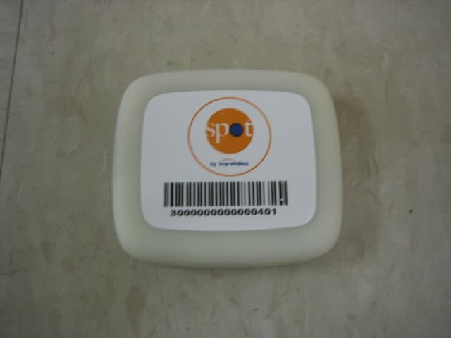
RO540002A001
Dec 05, 2006Spot Radio Frequency Location System - Asset Tag
Equipment Class
DSS - Part 15 Spread Spectrum Transmitter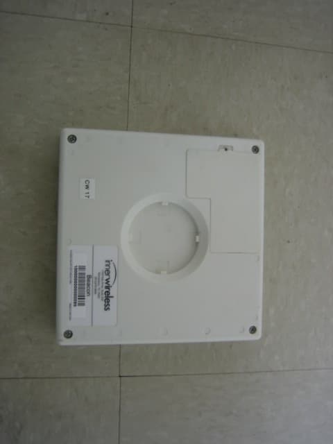
RO540001A001
Dec 05, 2006Spot Radio Frequency Location System - Beacon
Equipment Class
DSS - Part 15 Spread Spectrum Transmitter
RO540004A001
Dec 05, 2006Spot Radio Frequency Location System -Master Radio
Equipment Class
DSS - Part 15 Spread Spectrum Transmitter
RO5IWAPINTERFACEG
May 23, 2004Access Point System
Equipment Class
DTS - Digital Transmission System