RO5IWAPINTERFACEGAccess Point System
InnerWireless, Inc.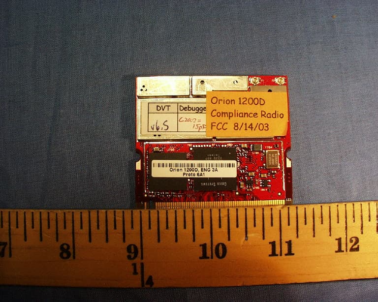
Click to zoom
Application Details
- Equipment Class
- DTS - Digital Transmission System
- Date of Grant
- May 23, 2004
- Application Purpose
- Original Equipment
- Date of Application
- May 23, 2004
- Equipment Note
- Access Point System
- Frequency Range
- 2412.00000000 - 2462.00000000
- Company
- InnerWireless, Inc.
- Country
- United States
Documents & Files
Document Text
Text extracted from the exhibit documents filed with the FCC. Open a document above to read the original.
Users Manual
CHAPTER First Draft - CISCO CONFIDENTIAL 7-1 Cisco Aironet 1200 Series Access Point Hardware Installation Guide OL-4310-02 7 2.4-GHz Radio Upgrade This chapter provides upgrade instructions for the 2.4-GHz (IEEE 802.11b-compliant or IEEE 802.11g-compliant) radio card and includes the following sections: •Upgrade Overview, page 7-2 •Opening the Access Cover, page 7-3 •Removing a Blank Spacer Card, page 7-4 •Removing a 2.4-GHz Radio, page 7-5 •Installing a 2.4-GHz Radio, page 7-7 First Draft - CISCO CONFIDENTIAL 7-2 Cisco Aironet 1200 Series Access Point Hardware Installation Guide OL-4310-02 Chapter 7 2.4-GHz Radio Upgrade Upgrade Overview Upgrade Overview This section provides instructions for upgrading the access point 2.4-GHz radio. The following operations summarize the upgrade procedure: 1.Remove all cables and power connections from the access point. 2.Follow standard electrostatic discharge (ESD) procedures. 3.Place the access point on an ESD-protected work surface. 4.Open the access point’s 2.4-GHz radio access cover. 5.For an access point without a 2.4-GHz radio feature, remove the blank spacer card. 6.For an access point with a 2.4-GHz radio feature, remove the existing 2.4-GHz radio card. 7.Install the new 2.4-GHz radio card. 8.Close the access point 2.4-GHz radio access cover. CautionESD can damage the Cisco Aironet radio and the internal components of the access point. It is recommended that the 2.4-GHz radio upgrade procedures be performed by an ESD-trained service technician at an ESD-protected workstation. NoteAfter you install the new radio, all configurable radio settings will be at default values. Refer to the Cisco IOS Software Configuration Guide for Cisco Aironet Access Points for complete instructions on configuring the new radio. Unpacking the Radio Each 2.4-GHz radio is shipped with the following items: •Quick start guide •A product registration card •A T-10 tamper-resistant Torx L-wrench •A 2.4-GHz radio compliance label If anything is missing or damaged, contact your Cisco representative for support. First Draft - CISCO CONFIDENTIAL 7-3 Cisco Aironet 1200 Series Access Point Hardware Installation Guide OL-4310-02 Chapter 7 2.4-GHz Radio Upgrade Opening the Access Cover Opening the Access Cover To open the 2.4-GHz radio access cover, follow these steps: Step 1Remove all cables and power connections from the access point. Step 2Remove all static-generating items from the work area, such as plastic material, styrofoam cups, and other similar items. Step 3Place the access point and the new 2.4-GHz radio (in its antistatic bag) on an antistatic work surface. Step 4Discharge any static buildup on your body by touching a grounded surface (antistatic work surface) before proceeding. Step 5Position the access point so that the bottom cover is facing up. CautionThe internal access point components and the 2.4-GHz radio can be damaged by ESD from improper handling. Step 6Remove the bottom access cover using the T-10 tamper-resistant Torx L-wrench provided with your Cisco radio card (see Figure 7-1). Figure 7-1Location of 2.4-GHz Radio Access Cover Screw If your access point was not configured with a 2.4-GHz radio, go to the “Removing a Blank Spacer Card” section. If you are replacing an existing 2.4-GHz radio, go to the “Removing a 2.4-GHz Radio” section. 1Access Cover Screw 1 74458 First Draft - CISCO CONFIDENTIAL 7-4 Cisco Aironet 1200 Series Access Point Hardware Installation Guide OL-4310-02 Chapter 7 2.4-GHz Radio Upgrade Removing a Blank Spacer Card Removing a Blank Spacer Card When your access point is not factory-configured with a 2.4-GHz radio, it contains a blank spacer card in the internal mini-PCI connector. You must remove the blank spacer card prior to installing a new 2.4-GHz radio card. CautionHandle all components carefully and observe all ESD precautions. The internal access point components and the 2.4-GHz radio can be damaged by ESD from improper handling. To remove the blank spacer card from the mini-PCI connector, following these steps: Step 1Push the card-retaining clips (on each side of card) away from the card (see Figure 7-2). When released, the board springs up. Figure 7-2Location of Retaining Clips on Blank Spacer Card Step 2 Carefully bend the card near the slots in opposite directions to provide enough clearance to remove the antenna wires. 1Card-retaining clips3Antenna connector (black wire) 2Antenna connector (white wire) 74248 1312 First Draft - CISCO CONFIDENTIAL 7-5 Cisco Aironet 1200 Series Access Point Hardware Installation Guide OL-4310-02 Chapter 7 2.4-GHz Radio Upgrade Removing a 2.4-GHz Radio Step 3Remove the antenna wires from the blank spacer card. CautionTo avoid damaging the antenna wire assemblies, handle them by their connectors. Step 4Remove the blank spacer card from the mini-PCI connector. For instructions on installing the radio card, go to the “Installing a 2.4-GHz Radio” section. Removing a 2.4-GHz Radio To remove a 2.4-GHz radio card from your access point, follow these steps: CautionThe internal access point components and the 2.4-GHz radio can be damaged by ESD from improper handling. Step 1Use your fingers to carefully remove the antenna wire connectors from the 2.4-GHz radio card. CautionThe antenna connectors can be damaged by using a pair of long-nose pliers during the removal process. CautionTo avoid damaging the antenna wire assemblies, handle them by their connectors. First Draft - CISCO CONFIDENTIAL 7-6 Cisco Aironet 1200 Series Access Point Hardware Installation Guide OL-4310-02 Chapter 7 2.4-GHz Radio Upgrade Removing a 2.4-GHz Radio Step 2Remove the 2.4-GHz radio card from the mini-PCI connector by performing the following operations: a.Push the card-retaining clips (on each side of card) away from the card (see Figure 7-3). When released, the radio card springs up (see Figure 7-4). Figure 7-3Location of Retaining Clips on 2.4-GHz Radio Card b. Grasp the radio card only on the edges, being careful not to to…
Text truncated - open the document above for the full version.
Users Manual
First Draft - CISCO CONFIDENTIAL Corporate Headquarters Cisco Systems, Inc. 170 West Tasman Drive San Jose, CA 95134-1706 USA http://www.cisco.com Tel: 408 526-4000 800 553-NETS (6387) Fax: 408 526-4100 Cisco Aironet 1200 Series Access Point Hardware Installation Guide Cisco IOS Release 12.2(13)JA October 2003 Customer Order Number: Text Part Number: OL-4310-02 First Draft - CISCO CONFIDENTIAL THE SPECIFICATIONS AND INFORMATION REGARDING THE PRODUCTS IN THIS MANUAL ARE SUBJECT TO CHANGE WITHOUT NOTICE. ALL STATEMENTS, INFORMATION, AND RECOMMENDATIONS IN THIS MANUAL ARE BELIEVED TO BE ACCURATE BUT ARE PRESENTED WITHOUT WARRANTY OF ANY KIND, EXPRESS OR IMPLIED. USERS MUST TAKE FULL RESPONSIBILITY FOR THEIR APPLICATION OF ANY PRODUCTS. THE SOFTWARE LICENSE AND LIMITED WARRANTY FOR THE ACCOMPANYING PRODUCT ARE SET FORTH IN THE INFORMATION PACKET THAT SHIPPED WITH THE PRODUCT AND ARE INCORPORATED HEREIN BY THIS REFERENCE. IF YOU ARE UNABLE TO LOCATE THE SOFTWARE LICENSE OR LIMITED WARRANTY, CONTACT YOUR CISCO REPRESENTATIVE FOR A COPY. The following information is for FCC compliance of Class A devices: This equipment has been tested and found to comply with the limits for a Class A digital device, pursuant to part 15 of the FCC rules. These limits are designed to provide reasonable protection against harmful interference when the equipment is operated in a commercial environment. This equipment generates, uses, and can radiate radio-frequency energy and, if not installed and used in accordance with the instruction manual, may cause harmful interference to radio communications. Operation of this equipment in a residential area is likely to cause harmful interference, in which case users will be required to correct the interference at their own expense. The following information is for FCC compliance of Class B devices: The equipment described in this manual generates and may radiate radio-frequency energy. If it is not installed in accordance with Cisco’s installation instructions, it may cause interference with radio and television reception. This equipment has been tested and found to comply with the limits for a Class B digital device in accordance with the specifications in part 15 of the FCC rules. These specifications are designed to provide reasonable protection against such interference in a residential installation. However, there is no guarantee that interference will not occur in a particular installation. Modifying the equipment without Cisco’s written authorization may result in the equipment no longer complying with FCC requirements for Class A or Class B digital devices. In that event, your right to use the equipment may be limited by FCC regulations, and you may be required to correct any interference to radio or television communications at your own expense. You can determine whether your equipment is causing interference by turning it off. If the interference stops, it was probably caused by the Cisco equipment or one of its peripheral devices. If the equipment causes interference to radio or television reception, try to correct the interference by using one or more of the following measures: • Turn the television or radio antenna until the interference stops. • Move the equipment to one side or the other of the television or radio. • Move the equipment farther away from the television or radio. • Plug the equipment into an outlet that is on a different circuit from the television or radio. (That is, make certain the equipment and the television or radio are on circuits controlled by different circuit breakers or fuses.) Modifications to this product not authorized by Cisco Systems, Inc. could void the FCC approval and negate your authority to operate the product. The Cisco implementation of TCP header compression is an adaptation of a program developed by the University of California, Berkeley (UCB) as part of UCB’s public domain version of the UNIX operating system. All rights reserved. Copyright © 1981, Regents of the University of California. NOTWITHSTANDING ANY OTHER WARRANTY HEREIN, ALL DOCUMENT FILES AND SOFTWARE OF THESE SUPPLIERS ARE PROVIDED “AS IS” WITH ALL FAULTS. CISCO AND THE ABOVE-NAMED SUPPLIERS DISCLAIM ALL WARRANTIES, EXPRESSED OR IMPLIED, INCLUDING, WITHOUT LIMITATION, THOSE OF MERCHANTABILITY, FITNESS FOR A PARTICULAR PURPOSE AND NONINFRINGEMENT OR ARISING FROM A COURSE OF DEALING, USAGE, OR TRADE PRACTICE. IN NO EVENT SHALL CISCO OR ITS SUPPLIERS BE LIABLE FOR ANY INDIRECT, SPECIAL, CONSEQUENTIAL, OR INCIDENTAL DAMAGES, INCLUDING, WITHOUT LIMITATION, LOST PROFITS OR LOSS OR DAMAGE TO DATA ARISING OUT OF THE USE OR INABILITY TO USE THIS MANUAL, EVEN IF CISCO OR ITS SUPPLIERS HAVE BEEN ADVISED OF THE POSSIBILITY OF SUCH DAMAGES. Cisco Aironet 1200 Series Access Point Hardware Installation Guide Copyright © 2003 Cisco Systems, Inc. All rights reserved. CCIP, CCSP, the Cisco Arrow logo, the Cisco Powered Network mark, Cisco Unity, Follow Me Browsing, FormShare, and StackWise are trademarks of Cisco Systems, Inc.; Changing the Way We Work, Live, Play, and Learn, and iQuick Study are service marks of Cisco Systems, Inc.; and Aironet, ASIST, BPX, Catalyst, CCDA, CCDP, CCIE, CCNA, CCNP, Cisco, the Cisco Certified Internetwork Expert logo, Cisco IOS, the Cisco IOS logo, Cisco Press, Cisco Systems, Cisco Systems Capital, the Cisco Systems logo, Empowering the Internet Generation, Enterprise/Solver, EtherChannel, EtherSwitch, Fast Step, GigaStack, Internet Quotient, IOS, IP/TV, iQ Expertise, the iQ logo, iQ Net Readiness Scorecard, LightStream, MGX, MICA, the Networkers logo, Networking Academy, Network Registrar, Pa cke t, PIX, Post-Routing, Pre-Routing, RateMUX, Registrar, ScriptShare, SlideCast, SMARTnet, StrataView Plus, Stratm, SwitchProbe, TeleRouter, The Fastest Way to Increase Your Internet Quotient, TransPath, and VCO are registered trademarks of Cisco Systems, Inc. and/or its affiliates in the U.S. and certain other countries. All other trademarks mentione…
Text truncated - open the document above for the full version.
Users Manual
InnerWireless, Inc. Richardson, Texas InnerWireless Access Point Interface COPYRIGHT© 2003 InnerWireless ALL RIGHTS RESERVED All information set forth in this document and all rights in and to intellectual property disclosed herein are the exclusive property of InnerWireless. No disclosure of this document and/or the information contained herein shall be made to any other person or organization without the prior written consent of InnerWireless. Table of Contents Table of Contents........................................................................................................- 2 - 1 FRONT CHAPTER...............................................................................................- 3 - 1.1 POLICY FOR INNERMOBILE ® SYSTEM WARRANTY AND SUPPORT SERVICES..............................................................................................................- 3 - 1.2 TO RETURN EQUIPMENT FOR REPAIR:...................................................- 4 - 1.3 CONVENTIONS............................................................................................- 4 - 1.4 RF EXPOSURE COMPLIANCE....................................................................- 4 - 1.5 PRECAUTIONS............................................................................................- 5 - 2 PURPOSE AND SCOPE.....................................................................................- 5 - 3 802.11 ACCESS POINT CONNECTION TO WDS SYSTEM..............................- 6 - - 2 - 1 FRONT CHAPTER 1.1 POLICY for InnerMobile ® System Warranty and Support Services 1.1.1 INNERMOBILE ® SYSTEM STANDARD WARRANTY InnerWireless, Inc. warrants, for a period of one (1) year beginning upon the sign off of the InnerWireless Acceptance Test Procedure (ATP) for the identified InnerMobile ® System provided herein, to be free from defects in materials and workmanship, and will operate and conform according to the product specifications. Warranty provided does not assure uninterrupted operation of the equipment, nor does it include any repairs necessitated by Customer’s, or third party’s, improper or unauthorized use or modification of the System. Customer accepts all responsibility for the physical security of the System. Warranty includes all parts and materials, with exceptions (see below), to meet the engineered specification contained in the contract. Customer will approve the engineered specifications per the InnerWireless acceptance and signoff procedure. InnerMobile ® Equipment included in warranty: In the event that service is disabled or degraded from it’s original design, InnerWireless warrants all original equipment installed as part of the InnerMobile ® System. The original equipment as it relates to the specific installation may include the following. • Coax cable required to deliver the RF signal through out each floor of the building • Jumper cables and connectors required to assemble the InnerMobile ® System • Access Point Interface (API) utilized as part of the InnerMobile ® System • Any antenna required to radiate the RF signal to the intended areas InnerWireless, Inc., at its sole discretion, will repair or replace any components of the InnerMobile ® System that are found to be faulty. Any replacements will be shipped from InnerWireless Inc. via next day delivery from the time the parts are available. InnerWireless will not maintain, or allow for the storage of spare components at the customer site. All warranty work shall be performed after notification by Customer that the system, or portion of the system, is inoperative, and Customer has followed the published procedures to troubleshoot and repair the failure without success. This warranty is expressly in lieu of any other warranties, express or implied, including any implied warranty of merchantability or warranty of fitness for a particular purpose, and of any other obligation or liability on the part of InnerWireless: InnerWireless neither assumes nor authorizes any other person to assume for it any liability in connection with its products. In no event shall InnerWireless be liable for any indirect, incidental, special or consequential damages arising out of the sale, manufacture or use of any of its products. In any event, the total liability of InnerWireless arising from any cause of action or claim whatsoever, whether (1) in contract, (2) in tort (including negligence, whether sole, joint, contributory, concurrent or otherwise), (3) under strict liability, (4) under any environmental or antipollution law or regulation, (5) connected with any toxic or hazardous substance or constituent, (6) arising out of any representation or instruction, or under any warranty, (7) or otherwise, arising out of, connected with, or resulting from the design, manufacture, sale, resale, delivery, repair, replacement or use of products or the furnishing of any service shall in no event exceed the price allocable to and paid to - 3 - InnerWireless for the individual unit of products or service or part thereof which gives rise to the cause of action or claim. 1.2 TO RETURN EQUIPMENT FOR REPAIR: • Be able to communicate to InnerWireless the nature of the problem with the equipment • Provide to InnerWireless your specific company name, ship to address, contact name and phone number. • Call the customer service center to set up appropriate return address, per the component being returned for repair. • InnerWireless return address: InnerWireless, Inc. Repair Services 1155 Kas Drive, Suite 200 Richardson, TX, 75081 1-866-472-9898 1.3 CONVENTIONS In this manual the following special formats are used: ! Warning WARNINGS CONTAIN INFORMATION REGARDING DANGEROUS FUNCTIONS. 1.4 RF EXPOSURE COMPLIANCE ! Warning TO COMPLY WITH FCC RF EXPOSURE COMPLIANCE REQUIREMENTS, ANTENNAS USED FOR THIS PRODUCT MUST BE FIXED MOUNTED ON INDOOR PERMANENT STRUCTURES, PROVIDING A SEPARATION DISTANCE OF AT LEAST 20 CM FROM ALL PERSONS DURING NORMAL OPERATION. - 4 - 1.5 PRECAUTIO…
Text truncated - open the document above for the full version.
Block Diagram
Block Dia g ram Output fr equency r a nge 400 – 24 85 M H z Eth e rn et 11 0V A C P.S . C i sco 120 0 Access Point P/N AI R - AP1230B- A - K 9 Oper ating band 2412 – 2 462 M H z Coax Cable RP-T NC to N ( ( P /N PE 35249- 48 ) Discone Antenna ( P /N 00702A001) ½” Radiating cable, N to N 10 ft. ( P /N AQ012J50) 50 Oh m T e rm . ( P /N 401- 1F3) Access Poin t Interface ( P /N 1100 1Q 00 2) Output fr equency r a nge 400 – 24 85 M H z Coax Cable RP-T NC to N ( P /N PE 35249- 48) Eth e rn et 11 0V A C P.S . C i sco 120 0 Access Point P/N AI R - AP1230B- A - K 9 Oper ating fr equency 2412 – 2 462 M H z ju m p e r cable , 4 m e ters ( P /N BN203763) Access Poin t Interface ( P /N 11 001 Q00 2 ) 50 Oh m T e rm . ( P /N 401- 1F3) LPA Antenna ( P /N 00701C00 1) Output fr equency r a nge 400 – 24 85 M H z Coax Cable RP-T NC to N ( P /N PE 35249- 48) Eth e rn et 11 0V A C P.S . C i sco 120 0 Access Point P/N AI R - AP1230B- A - K 9 Oper ating fr equency 2412 – 2 462 M H z Access Poin t Interface ( P /N 11 001 Q00 2 ) 50 Oh m T e rm . ( P /N 401- 1F3) ju m p e r cable , 4 m e ters ( P /N BN203763) PCB LPA Antenna ( P /N 00702L 001)
Cover Letter(s)
The Cisco AIR-MP21G-A-K9 module may be used with the following antennas: Antenna Type Model NumberGain dBi MPE cm Mode of Operation YagiAIR-ANT2410Y-R1012.5Point to Multipoint PatchAIR-ANT35498.510.5Point to Multipoint PatchAIR-ANT20126.58.4Point to Multipoint PatchAIR-ANT17296.07.9Point to Multipoint OmniAIR-ANT250657.0Omnidirectional OmniAIR-ANT321357.0Omnidirectional OmniAIR-ANT172857.0Omnidirectional OmniMaxrad MUF2400557.0Omnidirectional OmniMaxrad MAXC24005 57.0Omnidirectional PatchAIR-ANT319535.6Point to Multipoint DipoleAIR-ANT49412.25.1Omnidirectional Two Dipoles (Diversity Operation) Two AIR-ANT49412.25.1Omnidirectional OmniAIR-ANT35512.25.1Omnidirectional OmniAIR-ANT59592.05.0Omnidirectional
Cover Letter(s)
Jim Nicholson EMC Compliance Engineer Cisco Systems, Inc. 4125 Highlander Parkway Richfield, OH 44286 Phone: (330) 523-2094 Fax: (330) 523-2002 E-Mail: [email protected] September 2, 2003 Federal Communications Commission Equipment Authorization branch 7435 Oakland Mills Road Columbia, MD 21046 Re: FCC ID LDK102049: Request for Modular Transmitter Approval To Whom It May Concern: Cisco Systems, Inc. hereby requests Modular Transmitter Approval for the above listed FCC submittal. In support of this request, please note the declarations listed below. 1. The modular transmitter has its own RF shielding and does not rely upon the shielding provided by the device into which it is installed in order to comply with Part 15 limits. 2. The modular transmitter has buffered modulation/data inputs and will comply with Part 15 requirements under conditions of excessive data rates or over-modulation. 3. The modular transmitter has its own power supply regulation, and will comply with Part 15 requirements regardless of the design of the power supplying circuitry in the device into which the module is installed. 4. The modular transmitter complies with the antenna requirements of Section 15.203 and 15.204(c). The modular transmitter employs a “unique” antenna coupler, and all antennas used with the module are being approved with the module. 5. The modular transmitter was tested in a stand-alone configuration, and is capable of complying with Part 15 emission limits regardless of the device into which it is eventually installed. 6. The modular transmitter will be labeled with its own FCC ID number, and the outside of the device into which the module is installed will also display a label referring to the enclosed module. 7. The modular transmitter complies with the rules and operating requirements defined by Part 15.247. 8. The modular transmitter complies with all applicable RF exposure requirements. Jim Nicholson EMC Compliance Engineer Cisco Systems, Inc. 4125 Highlander Parkway Richfield, OH 44286 Phone: (330) 523-2094 Fax: (330) 523-2002 E-Mail: [email protected] Best Regards, Jim Nicholson EMC Compliance Engineer Cisco Systems, Inc.
Cover Letter(s)
Jim Nicholson EMC Compliance Engineer Cisco Systems, Inc. 4125 Highlander Parkway Richfield, OH 44286 Phone: (330) 523-2094 Fax: (330) 523-2002 E-Mail: [email protected] August 19, 2003 Federal Communications Commission Equipment Authorization branch 7435 Oakland Mills Road Columbia, MD 21046 Re: Request for Confidentiality To Whom It May Concern: The following information is to be held confidential pursuant to 47 CFR Part 0 §0.457 and Section 552(b)(4) of the Freedom of Information Act, because the information provided is proprietary and contains trade secrets. If made public, the information might be used to the disadvantage of the Cisco Systems, Inc. in the market place. Block Diagram Schematic Diagrams Technical Description Best Regards, Jim Nicholson EMC Compliance Engineer Cisco Systems, Inc.
Cover Letter(s)
Mike Kuo From: Claire Hoque Sent: September22 2003 Monday 4:49 PM To: Mike Kuo Cc: Michael Heckrotte Subject: RE: question#3 of TCB questions for Cisco FCC ID:LDK102049, AN03T3231(03U2181) Importance: High 9/24/2003 -----Original Message----- From: Michael Heckrotte Sent: Thursday, September 18, 2003 1:57 PM To: Mike Kuo; Claire Hoque Cc: Barbara Judge; Jim Nicholson (E-mail) Subject: RE: question#3 of TCB questions for FCC ID:LDK102049, AN03T3231(03U2181) Mike, The Cisco AIR-MP21G-A-K9 module may be used with the following antennas: Thanks, Mike -----Original Message----- From: Mike Kuo Sent: Thursday, September 18, 2003 9:43 AM To: Claire Hoque Cc: Michael Heckrotte Subject: RE: question#3 of TCB questions for FCC ID:LDK102049, AN03T3231(03U2181) Hi Clarie : Since some of antennas listed in the user manual are not necessary applicable to this device. Please provide an antenna list that will be used with this radio. Best Regards Antenna Type Model Number Gain dBi MPE cm Mode of Operation Yagi AIR-ANT2410Y-R 10 12.5 Point to Multipoint Patch AIR-ANT3549 8.5 10.5 Point to Multipoint Patch AIR-ANT2012 6.5 8.4 Point to Multipoint Patch AIR-ANT1729 6.0 7.9 Point to Multipoint Omni AIR-ANT2506 5 7.0 Omnidirectional Omni AIR-ANT3213 5 7.0 Omnidirectional Omni AIR-ANT1728 5 7.0 Omnidirectional Omni Maxrad MUF24005 5 7.0 Omnidirectional Omni Maxrad MAXC24005 5 7.0 Omnidirectional Patch AIR-ANT3195 3 5.6 Point to Multipoint Dipole AIR-ANT4941 2.2 5.1 Omnidirectional Two Dipoles (Diversity Operation) Two AIR-ANT4941 2.2 5.1 Omnidirectional Omni AIR-ANT3551 2.2 5.1 Omnidirectional Omni AIR-ANT5959 2.0 5.0 Omnidirectional Mike Kuo -----Original Message----- From: Claire Hoque Sent: Thursday, September 18, 2003 9:52 AM To: Mike Kuo Cc: Michael Heckrotte Subject: question#3 of TCB questions for FCC ID:LDK102049, AN03T3231(03U2181) Importance: High Hi Mike, Pls kindly read Jim's updated reply regarding question#3, and let us know if you could accept his explanation. If there are no further questions, pls issue the grant ASAP. Thanks, Claire Hoque -----Original Message----- From: Jim Nicholson [mailto:[email protected]] Sent: Thursday, September 18, 2003 7:47 AM To: 'Claire Hoque' Subject: RE: TCB questions for FCC ID:LDK102049, AN03T3231(03U2181) Claire, Regarding my response below for Question #3, the Orion radio for which we are applying for approval is an 802.11g radio. In the manual on the page you describe, I notice the 802.11g column does not reference an antenna with gain higher than 10 dBi. That being the case, I don't think a change is required to this section. The prior transmitter I referenced is covered under the 802.11b column. Let me know if this will fly. Thanks, jim -----Original Message----- From: Jim Nicholson [mailto:[email protected]] Sent: Wednesday, September 17, 2003 7:29 AM To: 'Claire Hoque' Subject: RE: TCB questions for FCC ID:LDK102049, AN03T3231(03U2181) Claire, Please see my comments in line below. Thanks, Jim -----Original Message----- From: Claire Hoque [mailto:[email protected]] Sent: Tuesday, September 16, 2003 7:46 PM To: '[email protected]' Subject: TCB questions for FCC ID:LDK102049, AN03T3231(03U2181) Hi Jim, Here are TCB questions for FCC ID:LDK102049, AN03T3231(03U2181). Michael Heckrotte has helped to give us some explanation(as attached). ____________________________________________________________________________ 9/24/2003 ____________________ Question #1: Based upon the antenna information given in Appendix B of user manual, Part No:AIR-ANT2012 is Spatial diversity antenna type with 6.5dBi gain. There is no test data for this type of antenna. Please provide your justification why this antenna is excluded from investigation. [JN] AIR-ANT2012 is a spatial diversity antenna in that there are two patch antennas in one package for diversity purposes. This 6.5 dBi patch antenna is covered by the testing of AIR-ANT3549 8.5 dBi patch antenna. Question #2: Part No:AIR-ANT3195 is listed in Appendix B but the test report did not list this antenna. Please confirm will this antenna be used with this transmitter. [JN] AIR-ANT3195 is not planned to be used with this transmitter, though there is no harm in including it in the approval. Question #3: Appendix B-6 of user manual mentioned three of antennas shall be installed to provide 2 meter separation distance to all users. One of antenna ( AIR-ANT1949 ) was not tested during final compliance tests. Per the antenna list in Appendix B-3, AIR-ANT1949 is yagi antenna with 13.5 dBi gain which is higher than AIR-ANT2410Y-R yagi-directional with 10dBi gain. Please provide your justification to state the reason that AIR-ANT1949 was not selected during final compliance tests. [JN] We will modify the Appendix B-6 and B-3. This manual covers a prior transmitter for this platform as well, and the higher gain antennas apply to the prior transmitter only. The transmitter being approved under LDK102049 does not support antennas with gain higher than 10 dBi. Question #4: Please confirm AIR-ANT24120, AIR-ANT4121 and AIR-ANT1949 antennas will require professional installation. [JN] AIR-ANT24120, AIR-ANT4121, and AIR-ANT1949 will not be used with the transmitter being approved under LDK102049 (see response to #3 above). Question #5: B-4 of user manual, please delete 2.1093 reference information from RF exposure compliance statement. This module can only be used as mobile device per section 2.1091 of FCC rules. 2.1093 is designed for portable device which is not applicable to this device. [JN] We will make this change. Question #6: Please confirm that this radio wit 2.2dBi antenna gain will be co-located with 5GHz Radio module ( FCC ID:LDK102045 ). No other 2.4GHz radio antenna will be co-located with 5GHz radio. [JN] Only the 2.2 dBi antenna will be located within 20 cm of the 5 GHz antennas. All other 2.4 GHz antennas will be located at least 20 dm away from the 5 GHz antennas. Question #7: Please confirm that this 2.4GHz radio will only …
Text truncated - open the document above for the full version.
Cover Letter(s)
Cisco Systems, Inc. 4125 Highlander Parkway Richfield, Ohio 44286 Phone: 330 523-2094 Fax: 330 523-2002 http://www.cisco.com Phone: (330) 523-2094 Fax: (330) 523-2002 E-Mail: [email protected] May 24, 2004 Federal Communications Commission Equipment Authorization Division, Application Processing Branch 7435 Oakland Mills Road Columbia, MD 21046 Re: FCC ID: RO5IWAPINTERFACEG To Whom It May Concern: The following information is to be held confidential pursuant to 47 CFR Part 0 §0.457 and Section 552(b)(4) of the Freedom of Information Act, because the information provided is proprietary and contains trade secrets. If made public, the information might be used to the disadvantage of the Cisco Systems, Inc. in the market place. Block Diagram Schematic Diagrams Technical Description Best Regards, Jim Nicholson EMC Compliance Engineer
Cover Letter(s)
From: [email protected] Sent: Friday, May 14, 2004 7:34 AM To: [email protected] Subject: Additional Documents The only change to this device was the Cisco card. All the documentation from the first submission not related to Cisco can be used as it has not changed. The documents from Cisco will have the updated information.
Cover Letter(s)
LET…
Text truncated - open the document above for the full version.
Contact Information
Applicant
James W. McCoy(Sr. Vice President & Chief Technical Officer)
Technical Contact
Nemko Dallas, Inc.David Light
[email protected]972-436-9600
802 N. Kealy · Lewisville, Texas · United States
Non-Technical Contact
Nemko Dallas, Inc.Tom Tidwell
[email protected]972-436-9600
Test Firm
Nemko USA, Inc.Tom Tidwell
Technical Specifications
| # | Rule Parts | Frequency Range | Power Output |
|---|---|---|---|
| 1 | 15C | 2.41 GHz - 2.46 GHz | 100.00 mW |
Other Applications from InnerWireless, Inc.
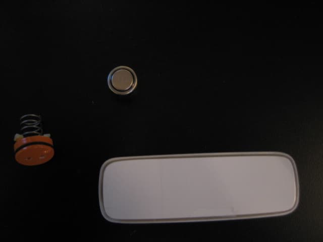
RO540009A001
Aug 02, 2007Spot Radio Freq. Location System - Mini Asset Tag
Equipment Class
DSS - Part 15 Spread Spectrum Transmitter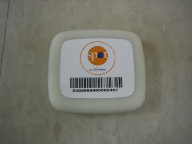
RO540002A001
Dec 05, 2006Spot Radio Frequency Location System - Asset Tag
Equipment Class
DSS - Part 15 Spread Spectrum Transmitter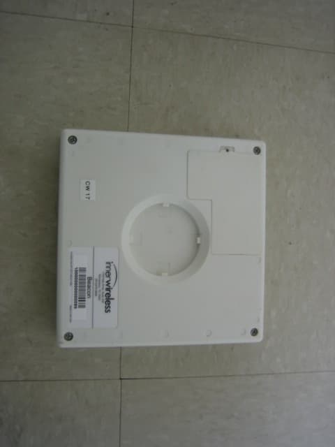
RO540001A001
Dec 05, 2006Spot Radio Frequency Location System - Beacon
Equipment Class
DSS - Part 15 Spread Spectrum Transmitter
RO540004A001
Dec 05, 2006Spot Radio Frequency Location System -Master Radio
Equipment Class
DSS - Part 15 Spread Spectrum Transmitter
RO5IWAPINTERFACE
Feb 29, 2004Access Point System
Equipment Class
DTS - Digital Transmission System