ROV-1MWR9165Focus StatSignal
Landis + Gyr, Inc.
Click to zoom
Application Details
- Equipment Class
- DXX - Part 15 Low Power Communication Device Transmitter
- Date of Grant
- Feb 23, 2004
- Application Purpose
- Original Equipment
- Date of Application
- Dec 30, 2003
- Equipment Note
- Focus StatSignal
- Frequency Range
- 916.50000000 - 916.50000000
- Company
- Landis + Gyr, Inc.
- Country
- United States
Documents & Files
Document Text
Text extracted from the exhibit documents filed with the FCC. Open a document above to read the original.
Users Manual
FOCUS kWh Solid-State Meter Technical Manual i Information in this document is subject to change without notice. No part of this document may be reproduced or transmitted in any form or by any means, electronic or mechanical, for any purpose without the express written permission of Landis+Gyr, Inc.. 2003 Landis+Gyr, Inc. All rights reserved. For further information, contact: Landis+Gyr, Inc. Meter Division 2800 Duncan Road Lafayette, IN 47904-5012 USA Tel. 765-742-1001 Document History Title: FOCUS Solid State Meter Technical Manual Document Number: Bulletin #??? Revision Date Description Level Issued Original 12/03 Initial Issue ii TABLE OF CONTENTS Purpose .................................................................................................................. ii Target Group.......................................................................................................... ii Conditions .............................................................................................................. ii Safety Warnings .................................................................................................... ii 1. Introduction to the FOCUS..........................................................................1 1.1. METER ASSEMBLY ....................................................................................... 1 1.2. BASEPLATE ASSEMBLY ................................................................................ 2 1.3. ELECTRONIC HOUSING ASSEMBLY............................................................... 2 2. The FOCUS Meter Family .............................................................................3 2.1. REGISTER TYPES......................................................................................... 3 3. Meter Assembly ...........................................................................................4 3.1. REMOVAL OF THE ELECTRONICS HOUSING FROM THE BASEPLATE .............. 4 3.2. INSTALLATION OF THE ELECTRONICS HOUSING ONTO THE BASEPLATE ...... 4 3.3. SEALING THE METER................................................................................... 4 4. Application Information ..............................................................................5 4.1. AVAILABLE METER FORMS........................................................................... 5 4.1.1. S-BASE ............................................................................................ 5 4.1.2. K-BASE ............................................................................................ 5 4.2. METER FORM SCHEMATIC DIAGRAMS.......................................................... 6 4.3. INSTALLATION PROCEDURES ...................................................................... 8 4.3.1. SOCKET BASE .................................................................................. 8 4.3.2. K-BASE ............................................................................................ 8 iii TABLE OF CONTENTS 5. Overview of Electronic Hardware................................................................9 5.1.1. LCD DISPLAY ................................................................................... 9 5.1.2. DISPLAY SCROLL SEQUENCE: ........................................................... 9 5.1.3. DISPLAY FORMAT .......................................................................... 10 5.1.4. DIGITAL POWER INDICATOR.......................................................... 10 5.1.5. POWER UP DISPLAY SEQUENCE...................................................... 10 5.2. DIAGNOSTICS ........................................................................................... 10 5.2.1. DIAGNOSTIC ERROR ...................................................................... 10 5.2.2. DIAGNOSTIC ERROR MAPPING ....................................................... 11 5.2.3. DIAGNOSTICS ERROR DISPLAY, POWER OUTAGE COUNTER, AND USER ACCESS ........................................................ 11 6. Configuring the Meter ...............................................................................12 6.1. CONFIGURATION PORT.................................................................. 12 6.1. 1 INITIAL POWER-UP AND OPERATION ............................................... 12 6.1.2 BILLING DATA RESET/PRESET ........................................................ 12 6.1.3 DISPLAY MULTIPLIER ..................................................................... 12 7. Meter Calibration.......................................................................................12 7.1. CALIBRATION LED..................................................................................... 12 7.1.1. FACTORY CALIBRATION ................................................................. 13 7.1.2. CUSTOMER CALIBRATION ADJUSTMENT........................................ 13 7.2. DATA RETENTION ..................................................................................... 13 8. Pulse Outputs ............................................................................................13 8.1. PULSE INITIATOR OUTPUT........................................................................ 13 8.2. COMMUNICATIONS ................................................................................... 13 iv Purpose This technical manual contains the following information: • Installation instructions, construction, characteristics and maintenance information • Performance and technical data Target Group The contents of this technical manual are intended for technically qualified personnel of energy supply companies responsible for the system planning, installation, commissioning, operation, maintenance, decommissioning and disposal of the meters. Conditions This technical manual is for personnel who are qualified and have received instructions in basic electrical principles, including safety procedures for installation of energy meters. Safety Warnings …
Text truncated - open the document above for the full version.
Block Diagram
System Block Diagram FCC ID: ROV-1MWR9165 Power Line Voltage Serial Comm. DC power Power Line Current Pulse_IN1 Pulse-IN2 RESET RELAY#1 PRODUCTION OPTICAL SERIAL INTERFACE Power Line connection FOCUS Meter Power Supply Measurement Data Processing & Communications AMR Modules StatSignal Radio KYZ RELAY Serial Comm. MUX
Cover Letter(s)
Authorized Agent: Radiometrics Midwest Corporation (815) 293-0772 – [email protected] Authorization Letter FCC ID: ROV-1MWR9165
External Photos
Authorized Agent: Radiometrics Midwest Corporation (815) 293-0772 – [email protected] External EUT Photographs FCC ID: ROV-1MWR9165 Front of EUT Rear of EUT
ID Label/Location Info
Authorized Agent: Radiometrics Midwest Corporation (815) 293-0772 – [email protected] ID Label/Location FCC ID: ROV-1MWR9165 • Material to be plastic • Text to be black letters on white background. • Text is guaranteed not to fade due to sunlight • Label is to be incorporated onto the meter’s faceplate. • Size to be 3 x 1.875 inches • Drawing of label Photograph of EUT showing Label Placement Radiometrics Midwest Corporation (815) 293-0772 – [email protected]
Internal Photos
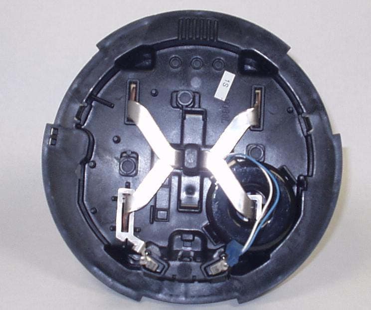
Authorized Agent: Radiometrics Midwest Corporation (815) 293-0772 – [email protected] Internal EUT Photographs FCC ID: ROV-1MWR9165 Photograph of EUT Front Cover Removed Photograph of Inside Front Cover Authorized Agent: Radiometrics Midwest Corporation (815) 293-0772 – [email protected] Photograph of Inside Front Cover (circuit board removed) Circuit Board: Component Side Authorized Agent: Radiometrics Midwest Corporation (815) 293-0772 – [email protected] Circuit Board: Foil Side
Operational Description
Copyright © 2003 Statsignal Systems, Inc. This document is company confidential. It must not be copied in whole or in part or released to any third party without the prior written consent of Statsignal Systems, Inc. FOCUS AMR Board Design Document Version 1.0 (Preliminary) October 13, 2003 Confidential 385760.DOC Statsignal Systems, Inc. Preliminary Confidential Page 1 Author: Ashok Mahadevan [email protected] Contributor(s): David Aldoretta [email protected] Revision History Date Revision done by Revision Comments October 9, 2003 Ashok Mahadevan 1.0 Initial version based on the S4 document Confidential 385760.DOC Statsignal Systems, Inc. Preliminary Confidential Page 2 Table of Contents 1. Introduction__________________________________________________________________________ 3 2. Power supply _________________________________________________________________________ 4 3. RF Transceiver _______________________________________________________________________ 6 4. RSSI monitoring ______________________________________________________________________ 7 5. Serial I/O and interfacing _______________________________________________________________ 8 5.1 Serial/RS232 level translation ___________________________________________________________ 9 6. Microcontroller ______________________________________________________________________ 10 7. PCB Layout Recommendations _________________________________________________________ 12 8. Firmware ___________________________________________________________________________ 13 8.1 Metrology Processing_________________________________________________________________ 14 8.2 Serial Processing ____________________________________________________________________ 15 8.3 Power supply/system monitoring _______________________________________________________ 15 8.4 RF processing _______________________________________________________________________ 16 Confidential 385760.DOC Statsignal Systems, Inc. Preliminary Confidential Page 3 1. Introduction This note attempts to document the design of the hardware for the Statsignal FOCUS AMR section. The AMR section is intended to be integrated in a Landis+GYR FOCUS electric meter, in all of its meter forms. The FOCUS AMR section will allow remote data acquisition from the FOCUS meter and enable the FOCUS meter to be a part of the Statsignal RF network. The FOCUS AMR board uses the RFM radio transceiver part with OOK mode of operation. The FOCUS AMR section is qualified for operation between a temperature range of –40C to +85C at all humidities, from 0 to 100% relative humidity and condensing. A block diagram of the FOCUS AMR board is shown along with the major signal paths. The FOCUS AMR board consists of the following major functional blocks: 1) Power supply 2) Microcontroller 3) RF Transceiver 4) RSSI measurement 5) Serial I/O and interfacing In addition to the major blocks mentioned, there are some smaller connections used as test/debug points, for tilt detection and JTAG programming of the microcontroller. MSP430F135 (Microcontroller) Focus AMR connector SS5494 (RF transceiver) RSSI Meas. RSSIOUT RSSIPWR CNTL1 BBOUT CNTL0 RFTXRFRX Power supply VHEAD VREF CHA RGE VCAPEN VCAP LP2951 (3V Reg.) 3V ERROR MAX3231 (RS232) Focus serial interface TXA MR RXA MR Focus serial connector SYSRST Confidential 385760.DOC Statsignal Systems, Inc. Preliminary Confidential Page 4 2. Power supply The power supply circuit provides the regulated 3VDC (Vcc) required to power the different sections of the FOCUS AMR board. The power supply circuit performs three major functions: voltage monitoring and sensing, supplying backup power using a Supercapacitor, and voltage regulation. Confidential 385760.DOC Statsignal Systems, Inc. Preliminary Confidential Page 5 The primary source of power is the unregulated DC voltage (VUNREG) coming from the FOCUS metrology section. During normal operation, the raw DC voltage is fed through Schottky diode D900 to the LP2951ACM-3.0 regulator U903. The 3VDC output of this regulator (Vcc) is used to power the FOCUS AMR section. The raw DC voltage is also used to charge the Supercapacitor C900 through a current limiting circuit comprised of Q900, Q901 and R929, with resistor R929 setting the charging current. R903, Q902 and R902 allow the microcontroller to turn ON/OFF the charging of the Supercapacitor by controlling the state of the CHARGE pin. The zener diode D902 is used to protect the Supercapacitor from being overcharged in case there is a firmware malfunction that leaves the charging circuit on permanently. R904, Q904A and Q903 form an analog switch that is controlled by the state of the VCAPEN pin from the microcontroller. When VCAPEN is asserted, Q904A and Q903 turn on and the voltage present on the Supercapacitor is available on the drain pin of Q903. Resistors R905 and R906 form a voltage divider that scales this voltage down and allows the microcontroller to read the Supercapacitor voltage on the VCAP pin. Note that the analog switch will not turn on until the voltage across the Supercapacitor reaches the minimum turn-on threshold (Vgs) of P-Channel MOSFET Q903. Thus, the Supercapacitor voltage cannot be monitored below about 2 VDC. The microcontroller can periodically monitor the voltage on the Supercapacitor, and if it falls below a preset firmware threshold, it can turn on the charging circuit. Once the voltage on the Supercapacitor rises above another preset firmware threshold, the microcontroller can then turn off the charging circuit. In this way, the voltage on the Supercapacitor can be continuously topped off by the microcontroller. Resistors R901 and R902 form a voltage divider that scales down the raw input VUNREG voltage. This scaled down voltage, available on the VREF pin, allows the microcontroller to monitor the VUNREG voltage and detect AC mains power outage condition. The zener diode D903 is used as protection if VUNREG should rise too high. When there is an AC mains voltag…
Text truncated - open the document above for the full version.
Test Report
Radiometrics Midwest Corporation Page 1 of 12 Electromagnetic Compatibility Test Report Tests Performed on a Landis+Gyr Electricity Meter w/StatSignal, Model Focus Radiometrics Document RP-5154A Product Detail: FCC ID: ROV-1MWR9165 Equipment type: Low Power 916 MHz Transmitter Test Standards: US CFR Title 47, Chapter I, FCC Part 15 Subpart C FCC Part 15 CFR Title 47: 2002 Industry Canada RSS-210, Issue 5 as required for Category I Equipment This report concerns: Original Grant for Certification FCC Part 15.249 RSS 210 Section 6.2.2 (m2) Tests Performed For: Test Facility: Landis+Gyr, Inc. 2800 Duncan Rd. Lafayette, IN 47904 Radiometrics Midwest Corporation 12 East Devonwood Romeoville, IL 60446 Phone: (815) 293-0772 e-mail: [email protected] Test Date(s): (Month-Day-Year) October 29 and 31, 2003 Document RP-5154A Revisions: Rev. Issue Date Affected Pages Revised By Authorized Signature for Revision 0 12/30/2003 RADIOMETRICS MIDWEST CORPORATION - EMC Test Report Equipment Tested (Company, Model, Product Name): Document No.: Page: Landis+Gyr, Focus, Electricity Meter w/StatSignal RP-5154A Rev. 0 2 of 12 Table of Contents 1 ADMINISTRATIVE DATA ................................................................................................................... 3 2 TEST SUMMARY AND RESULTS .....................................................................................................3 2.1 RF Exposure Compliance Requirements ..................................................................................... 3 3 EQUIPMENT UNDER TEST (EUT) DETAILS .................................................................................... 4 3.1 EUT Description ........................................................................................................................... 4 3.1.1 FCC Section 15.203 & RSS-210 Section 5.5 Antenna Requirements ................................... 4 3.2 Related Submittals ....................................................................................................................... 4 4 TESTED SYSTEM DETAILS .............................................................................................................. 4 4.1 Tested System Configuration ....................................................................................................... 4 4.2 Special Accessories ..................................................................................................................... 4 4.3 Equipment Modifications .............................................................................................................. 5 5 TEST SPECIFICATIONS AND RELATED DOCUMENTS.................................................................. 5 6 RADIOMETRICS’ TEST FACILITIES .................................................................................................5 7 DEVIATIONS AND EXCLUSIONS FROM THE TEST SPECIFICATIONS......................................... 6 8 CERTIFICATION ................................................................................................................................ 6 9 TEST EQUIPMENT TABLE ................................................................................................................ 6 10 TEST SECTIONS ............................................................................................................................. 7 10.1 AC Conducted Emissions; Section 15.207................................................................................. 7 10.1.1 Conducted Emissions Test Results ..................................................................................... 7 Figure 1. Conducted Emissions Test Setup.................................................................................... 8 10.2 Occupied Bandwidth (20 dB)...................................................................................................... 8 10.3 Radiated Emissions.................................................................................................................... 9 10.3.1 Radiated Emissions Field Strength Sample Calculation.................................................... 10 Figure 2. Drawing of Radiated Emissions Setup .......................................................................... 11 10.3.2 Radiated Emissions Test Results ...................................................................................... 12 Notice: This report must not be reproduced (except in full) without the written approval of Radiometrics Midwest Corporation. RADIOMETRICS MIDWEST CORPORATION - EMC Test Report Equipment Tested (Company, Model, Product Name): Document No.: Page: Landis+Gyr, Focus, Electricity Meter w/StatSignal RP-5154A Rev. 0 3 of 12 1 ADMINISTRATIVE DATA Equipment Under Test: A Landis+Gyr, Electricity Meter w/StatSignal Model: Focus Serial Number: 86 080 716 This will be referred to as the EUT in this Report Date EUT Received at Radiometrics: (Month-Day-Year) Test Date(s): (Month-Day-Year) 10/29/03 October 29 and 31, 2003 Test Report Written By: Test Witnessed By: Joseph Strzelecki Senior EMC Engineer Saieb Alrawi Senior Product Engineer Landis+Gyr Radiometrics’ Personnel Responsible for Test: Test Report Approved By Joseph Strzelecki Senior EMC Engineer NARTE EMC-000877-NE Chris W. Carlson Director of Engineering NARTE EMC-000921-NE 2 TEST SUMMARY AND RESULTS The EUT (Equipment Under Test) is an Electricity Meter w/StatSignal, Model Focus, manufactured by Landis+Gyr. The detailed test results are presented in a separate section. The following is a summary of the test results. Emissions Tests Results Environmental Phenomena Frequency Range Basic Standard Test Result RF Radiated Emissions 30-9300 MHz RSS-210 & FCC Part 15 Pass Conducted Emissions, AC Mains 0.15 - 30 MHz RSS-210 & FCC Part 15 Pass Occupied Bandwidth Test Fundamental Freq. RSS-210 & FCC Part 15 Pass 2.1 RF Exposure Compliance Requirements Since the EIRP is less than 1 mW, the EUT meets the FCC requirement fo…
Text truncated - open the document above for the full version.
Test Setup Photos
Authorized Agent: Radiometrics Midwest Corporation (815) 293-0772 – [email protected] Test Setup Photographs FCC ID: ROV-1MWR9165 Radiated Emissions: Authorized Agent: Radiometrics Midwest Corporation (815) 293-0772 – [email protected] Conducted Emissions:
Contact Information
Applicant
Saieb AlRawi(Sr. Product Engineer)
Technical Contact
Radiometrics Midwest CorporationJoseph R Strzelecki
[email protected]815-293-0772
12 East Devonwood Av. · Romeoville, Illinois · United States
Non-Technical Contact
Radiometrics Midwest CorporationJoan E Strzelecki
[email protected]815-293-0772
Test Firm
Radiometrics Midwest CorporationJoseph Strzelecki
815-293-0772Fax: 815-293-0820
Technical Specifications
| # | Rule Parts | Frequency Range | Power Output |
|---|---|---|---|
| 1 | 15C | 916.5 MHz - 916.5 MHz | - |
Other Applications from Landis + Gyr, Inc.
ROV-CLTR900M
Nov 10, 2004Digital transmission transmitter
Equipment Class
DTS - Digital Transmission System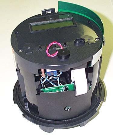
ROV-UTTR900M
Aug 04, 2004Meter with Utilinet transmitter
Equipment Class
DSS - Part 15 Spread Spectrum Transmitter