ROV-UTTR900MMeter with Utilinet transmitter
Landis + Gyr, Inc.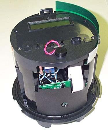
Click to zoom
Application Details
- Equipment Class
- DSS - Part 15 Spread Spectrum Transmitter
- Date of Grant
- Aug 04, 2004
- Application Purpose
- Original Equipment
- Date of Application
- Aug 04, 2004
- Equipment Note
- Meter with Utilinet transmitter
- Frequency Range
- 903.00000000 - 927.00000000
- Company
- Landis + Gyr, Inc.
- Country
- United States
Documents & Files
Document Text
Text extracted from the exhibit documents filed with the FCC. Open a document above to read the original.
Users Manual
Landis+Gyr Bulletin Number: 20031201 Rev A S4e-UtiliNet User Manual Page 1 of 13 S4e UtiliNet User Manual Bulletin Revision A Information in this document is subject to change without notice. No part of this document may be reproduced or transmitted in any form or by any means, electronic or mechanical, for any purpose without the express written permission of Landis+Gyr Inc. © 2003, Landis+Gyr Inc All rights reserved. For further information, contact: Landis+Gyr Inc 2800 Duncan Road Lafayette, IN 47904 USA Tel. 800-777-2774 Fax 765-742-0936 DOCUMENT HISTORY Bulletin: Revision Date Description Level Issued A Landis+Gyr Bulletin Number: 20031201 S4E-UtiliNet User Manual Page 2 of 13 SAFETY WARNINGS........................................................................................................... 3 FCC INFORMATION............................................................................................................ 4 INTRODUCTION.................................................................................................................. 4 SYSTEM OVERVIEW........................................................................................................... 5 S4E METER OVERVIEW...................................................................................................... 6 UTILINET MODULE OVERVIEW....................................................................................... 6 CONFIGURATION OF THE UTILINET MODULE............................................................. 7 METER SETUP...................................................................................................................... 7 METER INSTALLATION...................................................................................................... 9 TROUBLE SHOOTING GUIDE.......................................................................................... 10 USE OF EXTERNAL ANTENNAS....................................................................................... 10 TECHNICAL FEATURES OF THE S4E UTILINET........................................................... 12 Landis+Gyr Bulletin Number: 20031201 Rev A S4e-UtiliNet User Manual Page 3 of 13 Safety Warnings The following safety precautions must be observed during all phases of operation, service, and repair of this device. Failure to comply with these precautions or with specific warnings elsewhere in these instructions violates safety standards of design, manufacture, and the intended use of the metering instrument. Landis+Gyr Inc assumes no liability for the customer's failure to comply with these requirements. • Warning: Any work on, or near, energized meters, meter sockets, or other metering equipment can present a danger of electrical shock. All work on this product should be performed only by qualified electricians and metering specialists in accordance with local utility safety practices, utility requirements and procedures outlined in Chapter 14 of The Handbook for Electricity Metering (9th edition). The information contained within this manual is intended to be an aid to qualified metering personnel. It is not intended to replace the extensive training necessary to handle metering equipment in a safe manner. • Remove the meter from service prior to installing the antenna isolation kit and/or remote external antennas. • Be aware that dangerous voltages exist at several points within the meter when this product is installed on a meter socket. • Always disconnect power before meter disassembly, soldering, or replacing components. The S4e meter is connected directly to line potential. Due to the possibility of the potential lines being reversed, points accessible with the cover off may be at line voltage. LINE POTENTIAL IS PRESENT ON THE INCOMING CONNECTORS ON THE MEASUREMENT BOARD INCLUDING THE BATTERY CONNECTOR. The connectors have full-length insulators crimped onto each connector, which are shielded by the housing. However, pulling the connector loose will expose the battery terminals, which may be at line potential. The option board is connected directly to the main board and may be at a high potential. A Mylar shield prevents touching the option board. Removing the Mylar shield exposes line voltage. The above warning label affixed to the meter frame identifies hazards in the meter. Failure to follow all instructions may result in an unsafe product that could cause injury or death CAUTION: DO NOT OPERATE METER WITHOUT ANTENNA ATTACHED. OPERATION WITHOUT ANTENNA MAY CAUSE PERMANENT DAMAGE TO THE UTILINET MODULE. Landis+Gyr FCC Information This device complies with part 15 of the FCC rules. Operation is subject to the following two conditions: (1) This device may not cause harmful interference, and (2) This device must accept any interference received, including interference that may cause undesired operation. Changes or modifications not expressly approved by Landis+Gyr could void the user’s authority to operate the equipment. Note: This equipment has been tested and found to comply with the limits for a class B digital device, pursuant to part 15 of the FCC Rules. These limits are designed to provide reasonable protection against harmful interference in a residential installation. This equipment uses and can radiate radio frequency energy and, if not installed and used in accordance with the instructions, may cause harmful interference to radio communications. However, there is no guarantee that interference will not occur in a particular installation. If this equipment does cause harmful interference to radio or television reception, which can be determined by turning the equipment off and on, the user is encouraged to try to correct the interference by one or more of the following measures: - Reorient or relocate the receiving antenna. - Increase the separation between the equipment and receiver. - Connect the equipment into an outlet on a circuit different from that to which the receiver is connected. - …
Text truncated - open the document above for the full version.
Attestation Statements
Authorized Agent: Radiometrics Midwest Corporation (815) 293-0772 – [email protected] Authorization Letter FCC ID: ROV-UTTR900M
Attestation Statements
Authorized Agent: Radiometrics Midwest Corporation (815) 293-0772 – [email protected] Confidentiality Letter FCC ID: ROV-UTTR900M
External Photos
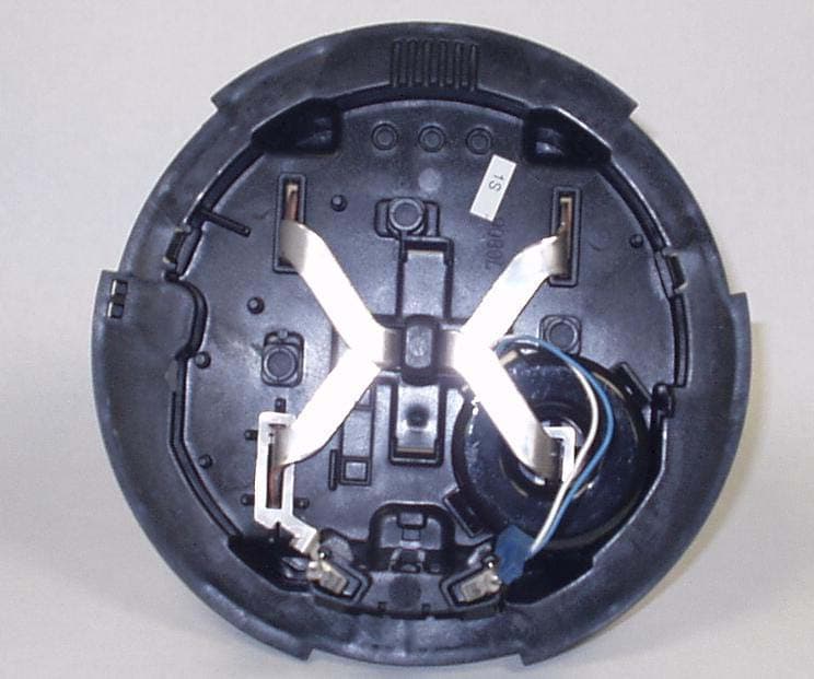
Authorized Agent: Radiometrics Midwest Corporation (815) 293-0772 – [email protected] External EUT Photographs FCC ID: ROV-UTTR900M Electricity meter Meter with mounting device Authorized Agent: Radiometrics Midwest Corporation (815) 293-0772 – [email protected] Meter without plastic cover These photos also show the antenna placement.
ID Label/Location Info
Authorized Agent: Radiometrics Midwest Corporation (815) 293-0772 – [email protected] ID Label/Location FCC ID: ROV-UTTR900M • The material is Gloss White polyester, 0.002 inches thick • The adhesive used is acrylic pressure-sensitive, tested for temperature range -40 C to +85 C. • Text to be Black on a white background • The size 11.8 x 5.5 cm • The label is mounted directly on the faceplate of the meter Photograph of label Radiometrics Midwest Corporation (815) 293-0772 – [email protected] This shows the location of the label on the EUT. The actual label is shown on the first page.
Internal Photos
Authorized Agent: Radiometrics Midwest Corporation (815) 293-0772 – [email protected] Internal EUT Photographs FCC ID: ROV-UTTR900M Transceiver PCB; Component side Authorized Agent: Radiometrics Midwest Corporation (815) 293-0772 – [email protected] Transceiver PCB; Foil side Transceiver PCB with RF shields removed. This shows the circuitry under the metal shield. Authorized Agent: Radiometrics Midwest Corporation (815) 293-0772 – [email protected] Transceiver Installed in meter Antenna Authorized Agent: Radiometrics Midwest Corporation (815) 293-0772 – [email protected] Electricity meter PCB; component side Foil side Interface board Foil Component side Authorized Agent: Radiometrics Midwest Corporation (815) 293-0772 – [email protected] EUT partially disassembled
RF Exposure Info
Authorized Agent: Radiometrics Midwest Corporation (815) 293-0772 – [email protected] RF exposure FCC ID: ROV-UTTR900M The output power of the EUT is 200 mW and the gain of the antenna is 2dBi The following information provides the minimum separation distance for the EUT, as calculated from FCC OET 65 Appendix B, Table 1B “Guidelines for General Population/Uncontrolled Exposure” This calculation is based on the highest EIRP possible from the EUT considering maximum power and antenna gain. The formulas were used: GP limit is = 0.62 mW/cm^2 for 928 MHz (from F/1500) Pwatts*Ggain or ERP = 10^(PdBm-30+GdBi)/10) =0.316 Watts 0.316 Watts = 25 dBm S= E^2/3770 mW/cm^2 E or V/m = (ERP*30)^0.5/d, (d in meters) d = ((ERP*30)/3770*S))^0.5 SMaximum AntennaMSD Freq.GP limitRF power GainERPEd MHzmW/cm^2 dBmdBiwattsV/mmeters 9030.6022320.31647.60.065 9270.6182320.31648.30.064 GP is the limit for general Population/Uncontrolled Exposure MSD is the minimum Seperation Distance NOTE: For mobile or fixed location transmitters, minimum separation distance is 20 cm, even if calculations indicate MPE distance is less
Test Report
Radiometrics Midwest Corporation (815) 293-0772 – www.radiomet.com Page 1 of 31 Electromagnetic Compatibility Test Report Tests Performed on a Landis + Gyr, Inc. Meter with Utilinet, Model S4e Form 16S Radiometrics Document RP-5294 Product Detail: FCC ID: ROV-UTTR900M Equipment type: 903 to 927 MHz Frequency Hopping Transmitter Test Standards: US CFR Title 47, Chapter I, FCC Part 15 Subpart C FCC Part 15 CFR Title 47: 2002 This report concerns: Original Grant for Certification FCC Part 15.247 Tests Performed For: Test Facility: Landis + Gyr, Inc. 2800 Duncan Rd. Lafayette, IN 47904-5012 Radiometrics Midwest Corporation 12 East Devonwood Romeoville, IL 60446 Phone: (815) 293-0772 e-mail: [email protected] Test Date(s): (Month-Day-Year) June 22 thru 23, 2004 Document RP-5294 Revisions: Rev. Issue Date Affected Pages Revised By Authorized Signature for Revision 0 July 12, 2004 RADIOMETRICS MIDWEST CORPORATION - EMC Test Report Testing of the Landis + Gyr, Inc., Model S4e Form 16S, Meter with Utilinet RP-5294 Rev. 0 Page 2 of 31 Table of Contents 1 ADMINISTRATIVE DATA ................................................................................................................... 3 2 TEST SUMMARY AND RESULTS .....................................................................................................3 2.1 RF Exposure Compliance Requirements ..................................................................................... 4 3 EQUIPMENT UNDER TEST (EUT) DETAILS .................................................................................... 4 3.1 EUT Description ........................................................................................................................... 4 3.1.1 FCC Section 15.203 & RSS-210 Section 5.5 Antenna Requirements ................................... 4 3.2 Related Submittals ....................................................................................................................... 4 4 TESTED SYSTEM DETAILS .............................................................................................................. 4 4.1 Tested System Configuration ....................................................................................................... 4 4.2 Special Accessories ..................................................................................................................... 5 4.3 Equipment Modifications .............................................................................................................. 5 5 TEST SPECIFICATIONS AND RELATED DOCUMENTS.................................................................. 5 6 RADIOMETRICS’ TEST FACILITIES .................................................................................................5 7 DEVIATIONS AND EXCLUSIONS FROM THE TEST SPECIFICATIONS......................................... 6 8 CERTIFICATION ................................................................................................................................ 6 9 TEST EQUIPMENT TABLE ................................................................................................................ 6 10 TEST SECTIONS ............................................................................................................................. 7 10.1 AC Conducted Emissions; Section 15.207................................................................................. 7 Figure 1. Conducted Emissions Test Setup.................................................................................... 8 10.2 Carrier Frequency Separation .................................................................................................... 8 10.3 Number of Hopping Frequencies .............................................................................................10 10.4 Time of Occupancy (Dwell Time) .............................................................................................13 10.5 Occupied Bandwidth (20 dB).................................................................................................... 13 10.6 Peak Output Power .................................................................................................................. 15 10.7 Band-edge Compliance of RF Conducted Emissions .............................................................. 16 10.8 Spurious RF Conducted Emissions.......................................................................................... 17 10.9 Spurious Radiated Emissions .................................................................................................. 25 10.9.1 Radiated Emissions Field Strength Sample Calculation.................................................... 26 Figure 2. Drawing of Radiated Emissions Setup .......................................................................... 27 10.9.2 Spurious Radiated Emissions Test Results (Restricted Band) ..................................... 27-31 Notice: This report must not be reproduced (except in full) without the written approval of Radiometrics Midwest Corporation. RADIOMETRICS MIDWEST CORPORATION - EMC Test Report Testing of the Landis + Gyr, Inc., Model S4e Form 16S, Meter with Utilinet RP-5294 Rev. 0 Page 3 of 31 1 ADMINISTRATIVE DATA Equipment Under Test: A Landis + Gyr, Inc., Meter with Utilinet Model: S4e Form 16S, Serial Number: 86 473 892 This will be referred to as the EUT in this Report Date EUT Received at Radiometrics: (Month-Day-Year) Test Date(s): (Month-Day-Year) June 22, 2004 June 22 thru 23, 2004 Test Report Written By: Test Witnessed By: Joseph Strzelecki Senior EMC Engineer NARTE EMC-000877-NE Saieb Alrawi Landis + Gyr, Inc. Radiometrics’ Personnel Responsible for Test: Test Report Approved By Joseph Strzelecki Senior EMC Engineer NARTE EMC-000877-NE Chris W. Carlson Director of Engineering NARTE EMC-000921-NE 2 TEST SUMMARY AND RESULTS The EUT (Equipment Under Test) is a Meter with Utilinet, Model S4e Form 16S, manufactured by La…
Text truncated - open the document above for the full version.
Test Setup Photos
Authorized Agent: Radiometrics Midwest Corporation (815) 293-0772 – [email protected] Test Setup Photographs FCC ID: ROV-UTTR900M Photograph of Radiated Emissions Test Setup (ANSI C63.4 Setup) Authorized Agent: Radiometrics Midwest Corporation (815) 293-0772 – [email protected] (ANSI C12.1 Setup) Photograph of Conducted Emissions Test Setup Authorized Agent: Radiometrics Midwest Corporation (815) 293-0772 – [email protected] Photograph of RF Conducted Tests
Contact Information
Applicant
Saieb AlRawi(Sr. Product Engineer)
Technical Contact
Radiometrics Midwest CorporationJoseph Strzelecki
[email protected]815-293-0772
12 East Devonwood Av. · Romeoville, Illinois · United States
Non-Technical Contact
Radiometrics Midwest CorporationJoan Strzelecki
[email protected]815-293-0772
Test Firm
Radiometrics Midwest Corp.Joseph Strzelecki
Technical Specifications
| # | Rule Parts | Frequency Range | Power Output |
|---|---|---|---|
| 1 | 15C | 903 MHz - 927 MHz | 200.00 mW |
Other Applications from Landis + Gyr, Inc.
ROV-CLTR900M
Nov 10, 2004Digital transmission transmitter
Equipment Class
DTS - Digital Transmission System
ROV-1MWR9165
Feb 23, 2004Focus StatSignal
Equipment Class
DXX - Part 15 Low Power Communication Device Transmitter