ROWCDT-XX5370WIFI Wireless Module
CHINA DRAGON TECHNOLOGY LIMITED
Click to zoom
Application Details
- Equipment Class
- DTS - Digital Transmission System
- Date of Grant
- Jan 29, 2013
- Application Purpose
- Original Equipment
- Date of Application
- Jan 29, 2013
- Equipment Note
- WIFI Wireless Module
- Frequency Range
- 2422.00000000 - 2452.00000000
- Country
- China
Documents & Files
Document Text
Text extracted from the exhibit documents filed with the FCC. Open a document above to read the original.
Users Manual
CHINADRAGON TECHNOLOGY LIMITED Version:V1.0 Date:2012.4.28 DESIGN:CHECK:APPROVAL: TheinformationcontainedhereinistheexclusivepropertyofCDT andshallnotbedistributed,reproducedordisclosedinwholeor noinpartwithoutpriorwrittenpermissionofCDT User Manual Productÿ CDT-XX5370-00~09 CHINA DRAGON TECHNOLOGYLIMITED DOCUMENT No : REG.DATE :2012.4.28 S P E C I F I C AT I O N REV.NO : 1.5 REV.DATE :2012.4.28 PAGE:2/15 ChangeHistoryofRevision ReversionDateContents of Revision ChangeRemark 1.02011.4.28 First release S.heng CHINA DRAGON TECHNOLOGYLIMITED DOCUMENT No : REG.DATE :2012.4.28 S P E C I F I C AT I O N REV.NO : 1. 5 REV.DATE :2012.4.28 PAGE :3/15 Table of Contents NoDescriptionPage 1Introduction -----------------------------------------------------4 2.Namingrule-----------------------------------------------------4 3.Features---------------------------------------------------------5 4.Ordering Information------------------------------------------5 5.Label marking--------------------------------------------------5 6.Block Diagram-------------------------------------------------6 7.Absolute Maximum Ratings--------------------------------6 8.Operating Conditions-----------------------------------------7 9.Standard Test Conditions------------------------------------7 10.Electrical Specifications--------------------------------------8 11.Environment Tests-------------------------------------------13 12.Pin Description-----------------------------------------------14 14.MechanicalDrawing&Mechanicalsize---------------15 CHINA DRAGON TECHNOLOGYLIMITED DOCUMENT No : REG.DATE :2012.4.28 S P E C I F I CAT I O N REV.NO : 1.5 REV.DATE :2012.4.28 PAGE:4/15 1.Introduction isanewgenerationofembeddedCDT-Wifiproductsmodule. CDT-WifiisbasedonCDTinterface,accordwithWifiwirelessnetworkstandardembedded module,thebuilt-inwirelessnetworkprotocolIEEE802.11protocolstack,andTCP/IPprotocol stack,saveelectricityintelligentcontrolprocedures Canrealize,theuserserialdatatothewirelessnetworkconversionbetween. ThroughtheCDT-Wifimodule,thetraditionalserialequipmentalsocaneasilyaccesswireless network. isinthefirsttwogenerationsofproductsbasedontop,andcarriesonthe comprehensivehardwareandsoftwareupgrades,functionmorepowerful,usemoresimple,lower powerconsumptionIntheoriginalfoundationabovetheintelligentcurrentcontrolprogram upgrade,thantheformertwogenerationproductprovinceelectricityabove40%. Intemperaturecompensation,theapplicationofthelatestsoftwareautomaticcontroltechnology, automatictemperatureadjustment,andwillnotaffectthedatatransmission,itsolvesthe traditionalproduct,becausethetemperaturetoohigh,causedataloss,frequentfallnets,etc 2.Namingrules: CDT - D 0 5370B A...C D E B FHJG I : 0:USB 1:MINIPCIE2:SDIO 8188E: Realtek8188CE 5572: Ralink5572 8188T: Realtek8188CTV 8188E: Realtek8188CE 5370B:Ralink5370B5931:MTK5931 CDT-XX5370-00~09 CDT-XX5370-00~09 CHINA DRAGON TECHNOLOGY LIMITED DOCUMENT No : REG.DATE :2012.4.28 S P E C I F I C ATI O N REV.NO : 1.5 REV.DATE :2012.4.28 PAGE :5/15 3. Features is the small size and low power module for IEEE 802.11b/g/n wireless LAN.is based on Ralink 5370B solution. IEEE 802.11Dual Band WLAN infrastructure Size : 25mm x 12mm x 0.6mm USB 2.0 Supports drivers for Windows Vista, 2000, XP, Linux Security : WPA,WPA2,AES(TKIP) • Application: DTV, DVR, HD DVDPlayer,Blue-rayDiskPlayer,STB 4. OrderingInformation ModelDescription C DT-D05370B-00Wi-Fi Module, 1T1R 5. Labelmarking ①CDT-D05370B-00 1111A0201④ ②: ③ 004TB5B00331 ①Model No④Product Lot No. : 1110A0401 ②MAC Address BAR Code-11 : Year- 02 : Date ③MAC Address No.- 11: Month- 01 : Manufactured - Revision No. : AProcess CDT-XX5370-00~09 CDT-XX5370-00~09 B/G/N CHINADRAGON TECHNOLOGY LIMITED DOCUMENT No : REG.DATE :2012.4.28 S P E C I F I C AT IO N REV.NO : 1.5 REV.DATE :2012.4.28 PAGE :6/15 6. Block Diagram 7.Absolute MaximumRatings Caution : The specifications in Table 1 define levels at which permanent damage to the device can occur. Function operation is not guaranteed under these conditions. Operating at absolute maximum conditions for extend periods can adversely affect the long-term reliability of the device. ParameterMinMaxUnit Storage Temperature-10 +80°C °C Storage Humidity (40°C)-90%% < Table 1 Absolute Maximum Ratings > . Other conditions 1) Do not use or store modules in the corrosive atmosphere, especially where chloride gas, sulfide gas, acid, alkali, salt or the like are contained. Also, avoid exposure to moisture. 2) Store the modules where the temperature and relative humidity do not exceed 5 to 40°Cand 20 to 60%. 3) Assemble the modules within 6 months. Check the soldering ability in case of 6 months over. CHINA DRAGON TECHNOLOGYLIMITED DOCUMENT No : REG.DATE :2012.4.28 S P E C I F I C AT I O N REV.NO : 1. 5 REV.DATE :2012.4.28 PAGE :7/15 8.OperatingConditions ParameterMinTypMax Unit OperatingTemperature0-+60 °C OperatingHumidity--85% SupplyVoltage2 VDD_3.3V2.73.34.0Vdc 9. Standard Test Conditions The Test for electrical specification shall be performed under the following condition unless otherwise specified. 1). Ambient condition Temperature :25°C± 5°C . Humidity:65%±5% R.H. 2). Power supply voltages 3.3V (±5%) input power at the Module 3). Current consumption over recommended range of supply voltage and operating conditions is like below. When it’s tested, it must be supplied more than 2 times of maximal current. CHINA DRAGON TECHNOLOGYLIMITED DOCUMENT No : REG.DATE :2012.4.28 S P E C I F I C AT I O N REV.NO : 1. 5 REV.DATE :2012.4.28 PAGE :8/15 10. ElectricalSpecifications 1) DC Characteristics CurrentConsumptionMin.Typ.Max.Unit TXMode(MCS7)-105-mA Idle and Associated state-50- Radio disabled state-10- 2) RF Characteristics for IEEE802.11b( 11Mbps mode unless otherwise specified) ItemsContents SpecificationIEEE802.11b ModeDSSS/CCK Channelfrequency2400 ~ 2483MHz Data rate 1,2,5.5,11Mbps TXCharacteristicsMin.Typ.Max.Unit PowerLevel12.51314dBm SpectrumMask 1 st side lobes(to fc ±11MHz)--43-30dBr 2 nd side lobes(to fc ±22MHz)--58-50dB…
Text truncated - open the document above for the full version.
Users Manual
CHINADRAGON TECHNOLOGY LIMITED Version:V1.0 Date:2012.4.28 DESIGN:CHECK:APPROVAL: TheinformationcontainedhereinistheexclusivepropertyofCDT andshallnotbedistributed,reproducedordisclosedinwholeor noinpartwithoutpriorwrittenpermissionofCDT User Manual Productÿ CDT-XX5370-00~09 CHINA DRAGON TECHNOLOGYLIMITED DOCUMENT No : REG.DATE :2012.4.28 S P E C I F I C AT I O N REV.NO : 1.5 REV.DATE :2012.4.28 PAGE:2/15 ChangeHistoryofRevision ReversionDateContents of Revision ChangeRemark 1.02011.4.28 First release S.heng CHINA DRAGON TECHNOLOGYLIMITED DOCUMENT No : REG.DATE :2012.4.28 S P E C I F I C AT I O N REV.NO : 1. 5 REV.DATE :2012.4.28 PAGE :3/15 Table of Contents NoDescriptionPage 1Introduction -----------------------------------------------------4 2.Namingrule-----------------------------------------------------4 3.Features---------------------------------------------------------5 4.Ordering Information------------------------------------------5 5.Label marking--------------------------------------------------5 6.Block Diagram-------------------------------------------------6 7.Absolute Maximum Ratings--------------------------------6 8.Operating Conditions-----------------------------------------7 9.Standard Test Conditions------------------------------------7 10.Electrical Specifications--------------------------------------8 11.Environment Tests-------------------------------------------13 12.Pin Description-----------------------------------------------14 14.MechanicalDrawing&Mechanicalsize---------------15 CHINA DRAGON TECHNOLOGYLIMITED DOCUMENT No : REG.DATE :2012.4.28 S P E C I F I CAT I O N REV.NO : 1.5 REV.DATE :2012.4.28 PAGE:4/15 1.Introduction isanewgenerationofembeddedCDT-Wifiproductsmodule. CDT-WifiisbasedonCDTinterface,accordwithWifiwirelessnetworkstandardembedded module,thebuilt-inwirelessnetworkprotocolIEEE802.11protocolstack,andTCP/IPprotocol stack,saveelectricityintelligentcontrolprocedures Canrealize,theuserserialdatatothewirelessnetworkconversionbetween. ThroughtheCDT-Wifimodule,thetraditionalserialequipmentalsocaneasilyaccesswireless network. isinthefirsttwogenerationsofproductsbasedontop,andcarriesonthe comprehensivehardwareandsoftwareupgrades,functionmorepowerful,usemoresimple,lower powerconsumptionIntheoriginalfoundationabovetheintelligentcurrentcontrolprogram upgrade,thantheformertwogenerationproductprovinceelectricityabove40%. Intemperaturecompensation,theapplicationofthelatestsoftwareautomaticcontroltechnology, automatictemperatureadjustment,andwillnotaffectthedatatransmission,itsolvesthe traditionalproduct,becausethetemperaturetoohigh,causedataloss,frequentfallnets,etc 2.Namingrules: CDT - D 0 5370B A...C D E B FHJG I : 0:USB 1:MINIPCIE2:SDIO 8188E: Realtek8188CE 5572: Ralink5572 8188T: Realtek8188CTV 8188E: Realtek8188CE 5370B:Ralink5370B5931:MTK5931 CDT-XX5370-00~09 CDT-XX5370-00~09 CHINA DRAGON TECHNOLOGY LIMITED DOCUMENT No : REG.DATE :2012.4.28 S P E C I F I C ATI O N REV.NO : 1.5 REV.DATE :2012.4.28 PAGE :5/15 3. Features is the small size and low power module for IEEE 802.11b/g/n wireless LAN.is based on Ralink 5370B solution. IEEE 802.11Dual Band WLAN infrastructure Size : 25mm x 12mm x 0.6mm USB 2.0 Supports drivers for Windows Vista, 2000, XP, Linux Security : WPA,WPA2,AES(TKIP) • Application: DTV, DVR, HD DVDPlayer,Blue-rayDiskPlayer,STB 4. OrderingInformation ModelDescription C DT-D05370B-00Wi-Fi Module, 1T1R 5. Labelmarking ①CDT-D05370B-00 1111A0201④ ②: ③ 004TB5B00331 ①Model No④Product Lot No. : 1110A0401 ②MAC Address BAR Code-11 : Year- 02 : Date ③MAC Address No.- 11: Month- 01 : Manufactured - Revision No. : AProcess CDT-XX5370-00~09 CDT-XX5370-00~09 B/G/N CHINADRAGON TECHNOLOGY LIMITED DOCUMENT No : REG.DATE :2012.4.28 S P E C I F I C AT IO N REV.NO : 1.5 REV.DATE :2012.4.28 PAGE :6/15 6. Block Diagram 7.Absolute MaximumRatings Caution : The specifications in Table 1 define levels at which permanent damage to the device can occur. Function operation is not guaranteed under these conditions. Operating at absolute maximum conditions for extend periods can adversely affect the long-term reliability of the device. ParameterMinMaxUnit Storage Temperature-10 +80°C °C Storage Humidity (40°C)-90%% < Table 1 Absolute Maximum Ratings > . Other conditions 1) Do not use or store modules in the corrosive atmosphere, especially where chloride gas, sulfide gas, acid, alkali, salt or the like are contained. Also, avoid exposure to moisture. 2) Store the modules where the temperature and relative humidity do not exceed 5 to 40°Cand 20 to 60%. 3) Assemble the modules within 6 months. Check the soldering ability in case of 6 months over. CHINA DRAGON TECHNOLOGYLIMITED DOCUMENT No : REG.DATE :2012.4.28 S P E C I F I C AT I O N REV.NO : 1. 5 REV.DATE :2012.4.28 PAGE :7/15 8.OperatingConditions ParameterMinTypMax Unit OperatingTemperature0-+60 °C OperatingHumidity--85% SupplyVoltage2 VDD_3.3V2.73.34.0Vdc 9. Standard Test Conditions The Test for electrical specification shall be performed under the following condition unless otherwise specified. 1). Ambient condition Temperature :25°C± 5°C . Humidity:65%±5% R.H. 2). Power supply voltages 3.3V (±5%) input power at the Module 3). Current consumption over recommended range of supply voltage and operating conditions is like below. When it’s tested, it must be supplied more than 2 times of maximal current. CHINA DRAGON TECHNOLOGYLIMITED DOCUMENT No : REG.DATE :2012.4.28 S P E C I F I C AT I O N REV.NO : 1. 5 REV.DATE :2012.4.28 PAGE :8/15 10. ElectricalSpecifications 1) DC Characteristics CurrentConsumptionMin.Typ.Max.Unit TXMode(MCS7)-105-mA Idle and Associated state-50- Radio disabled state-10- 2) RF Characteristics for IEEE802.11b( 11Mbps mode unless otherwise specified) ItemsContents SpecificationIEEE802.11b ModeDSSS/CCK Channelfrequency2400 ~ 2483MHz Data rate 1,2,5.5,11Mbps TXCharacteristicsMin.Typ.Max.Unit PowerLevel12.51314dBm SpectrumMask 1 st side lobes(to fc ±11MHz)--43-30dBr 2 nd side lobes(to fc ±22MHz)--58-50dB…
Text truncated - open the document above for the full version.
Block Diagram
USB Interface 3.3V 5V Interface Signals RT5370 Switch Regulator 1.5V SPI FLASH 2.4G TX0 / RX0 Diplexer Crystal 40MHz XTAL Antenna Serial EEPROM
Block Diagram
USB Interface 3.3V 5V Interface Signals RT5370 Switch Regulator 1.5V SPI FLASH 2.4G TX0 / RX0 Diplexer Crystal 40MHz XTAL Antenna Serial EEPROM
Cover Letter(s)
CHINA DRAGON TECHNOLOGY LIMITED Date: 2013/1/14 FCC ID: ROWCDT-XX5370 Subject: Ad Hoc Mode Function Declaration To Whom it may concern, This device is acting as slave and operating in the 2.4 GHz (2412 – 2462 MHz) band. Ad Hoc function is supported but not able to operate on non-US frequencies. Please contact the one signed below or the authorized agent for this filing. Thank you. Regards, Yours sincerely, Signatory Signature Name: Liu Xiaodong Title: Test Supervisor Tel: 15013625234 Fax: 0755-81449967
Cover Letter(s)
Authorization Letter We, (the approval holder) Company name China Dragon Technology Limited Addresss B4 Bidg, haosan No.1 lndustry Park, Shajing street, Bao’an Dist., City Shenzhen, Country China declare that the following representative (agent): Name (person) Bovey.yang Company name NTEK Testing Technology Co., Ltd. Addresss 1/F, Building E, Fenda Science Park Sanwei Community, Xixiang Street, Baoan District City Shenzhen Country China to act on our behalf on all matters concerning the application and documents submitted to PHOENIX TEST-LAB for product certification below Product Description CDT-XX5370-00~09 Type or Model(s) B0-9(5370), K0-9(5370), F0-9(5370), G0-9(5370), D0-9(5370), A0-9(5370) Tradename or Brand(s) N/A Attestation: City and Country: Date:Name: (this must be a person) Function:Signature: (or official company stamp) Shenzhen 2013/1/14 Liu Xiaodong Test Supervisor
Cover Letter(s)
FCC Confidentiality Request bTo the FCC and FCC TCB handling this application for certification Pursuant to 47 CFR Section 0.459(a) & (b), we, (the applicant / grantee) Company name China Dragon Technology Limited Addresss B4 Bidg, haosan No.1 lndustry Park, Shajing street, Bao’an Dist., City Shenzhen, Country china request non-disclosure and confidential treatment for our certification under: Grantee Code Product Number FCC ID: ROW CDT-XX5370 of the following materials submitted within this certification application: (please cross what is applicable, or add other documents) X Operational Description X Schematics Diagrams Above materials contain secrets, proprietary and technical information, which would customarily be guarded from competitors under 47 CFR, section 0.457(d)(2). Disclosure or publication or any portion of this company confidential material to other parties could cause substantial competitive harm and provide unjustified benefits for competitors. We understand that pursuant to 47 CFR section 0.457(d)(1)(ii) disclosure of the applicant and all accompanying documentation will not be made before the date of the grant. Attestation: City and Country: Date:Name: (this must be a person) Function:Signature: (or official company stamp) Shenzhen 2013/1/14 Liu Xiaodong Test Supervisor
Cover Letter(s)
To whom it may concern: (FCC ID: ROWCDT-XX5370) meets the requirements asset forth in DA 00-1407: 1. The modular transmitter must have its own RF shielding. This is intended to ensure that the module does not have to rely upon the shielding provided by the device into which it is installed in order for all modular transmitter emissions to comply with Part 15 limits. It is also intended to prevent coupling between the RF circuitry of the module and any wires or circuits in the device into which the module is installed. Such coupling may result in non-compliant operation. The moduar no shielded 2. The modular transmitter must have buffered modulation/data inputs (if such inputs are provided) to ensure that the module will comply with Part 15 requirements under conditions of excessive data rates or over-modulation. The EUT has buffered data inputs, it is integrated in chip RT5370 3. The modular transmitter must have its own power supply regulation. This is intended to ensure that the module will comply with Part 15 requirements regardless of the design of the power supplying circuitry in the device into which the module is installed. The module has a voltage regulator circuit as well as instructions as to the proper supply voltages required for operation. Please refer to operation Description 4. The modular transmitter must comply with the antenna requirements of Section 15.203 and 15.204(c). The antenna must either be permanently attached or employ a “unique” antenna coupler (at all connections between the module and the antenna, including the cable). Any antenna used with the module must be approved with the module, either at the time of initial authorization or through a Class II permissive change. The “professional installation” provision of Section 15.203 may not be applied to modules. The EUT’s antenna is External(U-FL Connector) antenna. It comply with the standard requirement 5. The modular transmitter must be tested in a stand-alone configuration, i.e., the module must not be inside another device during testing. This is intended to demonstrate that the module is capable of complying with Part 15 emission limits regardless of the device into which it is eventually installed. Unless the transmitter module will be battery powered, it must comply with the AC line conducted requirements found in Section 15.207. AC or DC power lines and data input/output lines connected to the module must not contain ferrites, unless they will be marketed with the module (see Section 15.27(a)). The length of these lines shall be length typical of actual use or, if that length is unknown, at least 10 centimeters to insure that there is no coupling between the case of the module and supporting equipment. Any accessories, peripherals, or support equipment connected to the module during testing shall be unmodified or commercially available (see Section 15.31(i)). As shown in the test setup photos, the module was tested in the open with external antenna It was powered via the evaluation board. 6. The modular transmitter must be labeled with its own FCC ID number, and, if the FCC ID is not visible when the module is installed inside another device, then the outside of the device into which the module is installed must also display a label referring to the enclosed module. This exterior label can use wording such as the following: “Contains Transmitter Module FCC ID: XYZMODEL1” or “Contains FCC ID: XYZMODEL1.” Any similar wording that expresses the same meaning may be used. The Grantee may either provide such a label, an example of which must be included in the application for equipment authorization, or, must provide adequate instructions along with the module which explain this requirement. In the latter case, a copy of these instructions must be included in the application for equipment authorization. The instructions provided to the user provide information as to how to properly apply the FCC ID to the finished product. The module is labeled with the FCC ID and the artwork is provided. 7. The modular transmitter must comply with any specific rule or operating requirements applicable to the transmitter and the manufacturer must provide adequate instructions along with the module to explain any such requirements. A copy of these instructions must be included in the application for equipment authorization. For example, there are very strict operational and timing requirements that must be met before a transmitter is authorized for operation under Section 15.231. For instance, data transmission is prohibited, except for operation under Section 15.231(e), in which case there are separate field strength level and timing requirements. Compliance with these requirements must be assured. The operational description and users guides provide this detail. 8. The modular transmitter must comply with any applicable RF exposure requirements. For example, FCC Rules in Sections 2.1091, 2.1093 and specific Sections of Part 15, including 15.319(i), 15.407(f), 15.253(f) and 15.255(g), require that Unlicensed PCS, UNII and millimeter wave devices perform routine environmental evaluation for RF Exposure to demonstrate compliance. In addition, spread spectrum transmitters operating under Section 15.247 are required to address RF Exposure compliance in accordance with Section 15.247(b)(4). Modular transmitters approved under other Sections of Part 15, when necessary, may also need to address certain RF Exposure concerns, typically by providing specific installation and operating instructions for users, installers and other interested parties to ensure compliance. The EUT is compliant with all applicable RF exposure requirements. This evaluation is found in in the’ RF EXPOSURE TEST ‘ file. Sincerely, Liu Xiaodong 2013.1.10
Cover Letter(s)
CHINA DRAGON TECHNOLOGY LIMITED Date: 2013/1/14 FCC ID: ROWCDT-XX5370 Subject: Ad Hoc Mode Function Declaration To Whom it may concern, This device is acting as slave and operating in the 2.4 GHz (2412 – 2462 MHz) band. Ad Hoc function is supported but not able to operate on non-US frequencies. Please contact the one signed below or the authorized agent for this filing. Thank you. Regards, Yours sincerely, Signatory Signature Name: Liu Xiaodong Title: Test Supervisor Tel: 15013625234 Fax: 0755-81449967
Cover Letter(s)
Authorization Letter We, (the approval holder) Company name China Dragon Technology Limited Addresss B4 Bidg, haosan No.1 lndustry Park, Shajing street, Bao’an Dist., City Shenzhen, Country China declare that the following representative (agent): Name (person) Bovey.yang Company name NTEK Testing Technology Co., Ltd. Addresss 1/F, Building E, Fenda Science Park Sanwei Community, Xixiang Street, Baoan District City Shenzhen Country China to act on our behalf on all matters concerning the application and documents submitted to PHOENIX TEST-LAB for product certification below Product Description CDT-XX5370-00~09 Type or Model(s) B0-9(5370), K0-9(5370), F0-9(5370), G0-9(5370), D0-9(5370), A0-9(5370) Tradename or Brand(s) N/A Attestation: City and Country: Date:Name: (this must be a person) Function:Signature: (or official company stamp) Shenzhen 2013/1/14 Liu Xiaodong Test Supervisor
Cover Letter(s)
FCC Confidentiality Request bTo the FCC and FCC TCB handling this application for certification Pursuant to 47 CFR Section 0.459(a) & (b), we, (the applicant / grantee) Company name China Dragon Technology Limited Addresss B4 Bidg, haosan No.1 lndustry Park, Shajing street, Bao’an Dist., City Shenzhen, Country china request non-disclosure and confidential treatment for our certification under: Grantee Code Product Number FCC ID: ROW CDT-XX5370 of the following materials submitted within this certification application: (please cross what is applicable, or add other documents) X Operational Description X Schematics Diagrams Above materials contain secrets, proprietary and technical information, which would customarily be guarded from competitors under 47 CFR, section 0.457(d)(2). Disclosure or publication or any portion of this company confidential material to other parties could cause substantial competitive harm and provide unjustified benefits for competitors. We understand that pursuant to 47 CFR section 0.457(d)(1)(ii) disclosure of the applicant and all accompanying documentation will not be made before the date of the grant. Attestation: City and Country: Date:Name: (this must be a person) Function:Signature: (or official company stamp) Shenzhen 2013/1/14 Liu Xiaodong Test Supervisor
Cover Letter(s)
To whom it may concern: (FCC ID: ROWCDT-XX5370) meets the requirements asset forth in DA 00-1407: 1. The modular transmitter must have its own RF shielding. This is intended to ensure that the module does not have to rely upon the shielding provided by the device into which it is installed in order for all modular transmitter emissions to comply with Part 15 limits. It is also intended to prevent coupling between the RF circuitry of the module and any wires or circuits in the device into which the module is installed. Such coupling may result in non-compliant operation. The moduar no shielded 2. The modular transmitter must have buffered modulation/data inputs (if such inputs are provided) to ensure that the module will comply with Part 15 requirements under conditions of excessive data rates or over-modulation. The EUT has buffered data inputs, it is integrated in chip RT5370 3. The modular transmitter must have its own power supply regulation. This is intended to ensure that the module will comply with Part 15 requirements regardless of the design of the power supplying circuitry in the device into which the module is installed. The module has a voltage regulator circuit as well as instructions as to the proper supply voltages required for operation. Please refer to operation Description 4. The modular transmitter must comply with the antenna requirements of Section 15.203 and 15.204(c). The antenna must either be permanently attached or employ a “unique” antenna coupler (at all connections between the module and the antenna, including the cable). Any antenna used with the module must be approved with the module, either at the time of initial authorization or through a Class II permissive change. The “professional installation” provision of Section 15.203 may not be applied to modules. The EUT’s antenna is External(U-FL Connector) antenna. It comply with the standard requirement 5. The modular transmitter must be tested in a stand-alone configuration, i.e., the module must not be inside another device during testing. This is intended to demonstrate that the module is capable of complying with Part 15 emission limits regardless of the device into which it is eventually installed. Unless the transmitter module will be battery powered, it must comply with the AC line conducted requirements found in Section 15.207. AC or DC power lines and data input/output lines connected to the module must not contain ferrites, unless they will be marketed with the module (see Section 15.27(a)). The length of these lines shall be length typical of actual use or, if that length is unknown, at least 10 centimeters to insure that there is no coupling between the case of the module and supporting equipment. Any accessories, peripherals, or support equipment connected to the module during testing shall be unmodified or commercially available (see Section 15.31(i)). As shown in the test setup photos, the module was tested in the open with external antenna It was powered via the evaluation board. 6. The modular transmitter must be labeled with its own FCC ID number, and, if the FCC ID is not visible when the module is installed inside another device, then the outside of the device into which the module is installed must also display a label referring to the enclosed module. This exterior label can use wording such as the following: “Contains Transmitter Module FCC ID: XYZMODEL1” or “Contains FCC ID: XYZMODEL1.” Any similar wording that expresses the same meaning may be used. The Grantee may either provide such a label, an example of which must be included in the application for equipment authorization, or, must provide adequate instructions along with the module which explain this requirement. In the latter case, a copy of these instructions must be included in the application for equipment authorization. The instructions provided to the user provide information as to how to properly apply the FCC ID to the finished product. The module is labeled with the FCC ID and the artwork is provided. 7. The modular transmitter must comply with any specific rule or operating requirements applicable to the transmitter and the manufacturer must provide adequate instructions along with the module to explain any such requirements. A copy of these instructions must be included in the application for equipment authorization. For example, there are very strict operational and timing requirements that must be met before a transmitter is authorized for operation under Section 15.231. For instance, data transmission is prohibited, except for operation under Section 15.231(e), in which case there are separate field strength level and timing requirements. Compliance with these requirements must be assured. The operational description and users guides provide this detail. 8. The modular transmitter must comply with any applicable RF exposure requirements. For example, FCC Rules in Sections 2.1091, 2.1093 and specific Sections of Part 15, including 15.319(i), 15.407(f), 15.253(f) and 15.255(g), require that Unlicensed PCS, UNII and millimeter wave devices perform routine environmental evaluation for RF Exposure to demonstrate compliance. In addition, spread spectrum transmitters operating under Section 15.247 are required to address RF Exposure compliance in accordance with Section 15.247(b)(4). Modular transmitters approved under other Sections of Part 15, when necessary, may also need to address certain RF Exposure concerns, typically by providing specific installation and operating instructions for users, installers and other interested parties to ensure compliance. The EUT is compliant with all applicable RF exposure requirements. This evaluation is found in in the’ RF EXPOSURE TEST ‘ file. Sincerely, Liu Xiaodong 2013.1.10
Cover Letter(s)
China Dragon Technology Limited Model Difference FCC ID: ROWCDT-XX5370 Model : B0-9(5370), K0-9(5370), F0-9(5370), G0-9(5370), D0-9(5370), A0-9(5370) All the model are the same circuit and RF module,except the model name. Regards, Yours sincerely, Signature Name: Liu Xiaodong Title: Test Supervisor Te l : 15017940116 Company : China Dragon Technology Limited Add: B4 Bidg, haosan No.1 lndustry Park, Shajing street, Bao’an Dist., Shenzhen, China
Cover Letter(s)
China Dragon Technology Limited Model Difference FCC ID: ROWCDT-XX5370 Model : B0-9(5370), K0-9(5370), F0-9(5370), G0-9(5370), D0-9(5370), A0-9(5370) All the model are the same circuit and RF module,except the model name. Regards, Yours sincerely, Signature Name: Liu Xiaodon…
Text truncated - open the document above for the full version.
Contact Information
Applicant
Song xiaoyue
Test Firm
Shenzhen NTEK Testing Technology Co., Ltd.Jason Chen
Technical Specifications
| # | Rule Parts | Frequency Range | Power Output |
|---|---|---|---|
| 2 | 15C | 2.42 GHz - 2.45 GHz | 9.50 mW |
Other Applications from CHINA DRAGON TECHNOLOGY LIMITED

ROW-W691612A-00
Jul 16, 2026WLAN 802.11b/g/n/ax UART 1T1R + BT 5.0 module
Equipment Class
DTS - Digital Transmission System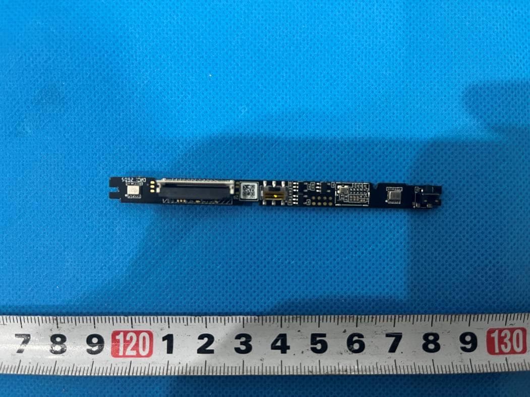
ROWR2
Apr 22, 202660G Radar module
Equipment Class
FDS - Part 15 Field Disturbance Sensor
ROW-CDW69868500
Mar 12, 2024WiFi Module
Equipment Class
DTS - Digital Transmission System
ROW-CDWU96600A00
Sep 19, 2023Wi-Fi Module
Equipment Class
DTS - Digital Transmission System
ROW-E3ESP3200
Mar 21, 2022WiFi Module
Equipment Class
DTS - Digital Transmission System