RPZMED-1000KEYBOARD
Dobbs-Stanford Corporation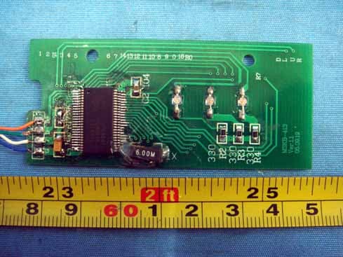
Click to zoom
Application Details
- Equipment Class
- JBP - Part 15 Class B Computing Device Peripheral
- Date of Grant
- Jan 24, 2006
- Application Purpose
- Original Equipment
- Date of Application
- Jan 24, 2006
- Equipment Note
- KEYBOARD
- Company
- Dobbs-Stanford Corporation
- Country
- United States
Documents & Files
Document Text
Text extracted from the exhibit documents filed with the FCC. Open a document above to read the original.
Users Manual
Manual NOTE: This equipment has been tested and found to comply with the limits for a Class B digital device, pursuant to part 15 of the FCC Rules. These limits are designed to provide reasonable protection against harmful interference in a residential installation. This equipment generates, uses and can radiate radio frequency energy and, if not installed and used in accordance with the instructions, may cause harmful interference to radio communications. However, there is no guarantee that interference will not occur in a particular installation. If this equipment does cause harmful interference to radio or television reception, which can be determined by turning the equipment off and on, the user is encouraged to try to correct the interference by one or more of the following measures: - Reorient or relocate the receiving antenna. - Increase the separation between the equipment and receiver. -Connect the equipment into an outlet on a circuit different from that to which the receiver is connected. -Consult the dealer or an experienced radio/TV technician for help. FCC Note: THE MANUFACTURER IS NOT RESPONSIBLE FOR ANY RADIO OR TV INTERFERENCE CAUSED BY UNAUTHORIZED MODIFICATIONS TO THIS EQUIPMENT. SUCH MODIFICATIONS COULD VOID THE USER'S AUTHORITY TO OPERATE THE EQUIPMENT.
External Photos
EUT - Front View EUT - Back View
ID Label/Location Info
FCC ID Label Location This device complies with Part 15 of the FCC Rules. Operation is subject to the following two conditions:(1) this device may not cause harmful interference, and (2) this device must accept any interference received, including interference that may cause undesired operation The Label must not be a stick-on paper. The Label on these products must be permanently affixed to the product and readily visible at the time of purchase and must last the expected lifetime of the equipment not be readily detachable. Proposed Label Location on EUT EUT Bottom View/proposed FCC Mark Location This device complies with Part 15 of the FCC Rules. Operation is subject to the following two conditions: 1. This device may not cause harmful interference, and 2. This device must accept any interference received, including interference that may cause undesired operation.
ID Label/Location Info
FCC ID Label Sample for Model MED-1000 FCC ID: RPZMED-1000 Made in China This device complies with Part 15 of the FCC Rules. Operation is subject to the following two conditions: 1. This device may not cause harmful interference, and 2. This device must accept any interference received, including interference that may cause undesired operation.
Internal Photos
PCB - Solder View PCB - Component View
Operational Description
5Use the scroll in the keyboard can process the mouse function
Schematics
1 2 34 ABCD 4 3 2 1 D CBA Title Number Revision Size A4 Date: 20-Jan-2006 Sheet of File: \\Linda\FCC ID\XMD\MSKEY.DDB Drawn By: 1 48 2 47 3 46 4 45 5 44 6 43 7 42 8 41 9 40 10 39 11 38 12 37 13 36 14 35 15 34 16 33 17 32 18 31 19 30 20 29 21 28 22 27 23 26 24 25 D+D-P37P35P33P31P27P25P23P21P17P15P13P11NCNCP07P05P03P01NCNCVPPVSS XTL XTLNCNCP00P02P04P06NCNCP10P12P14P16P20P22P24P26P30P32P34P36VSSVCC U1 CY7C63413_SSOP 48PIN C1C0C2C4C6C8C10C12C14 R0R2R4R6 C16 CAPS X1Y1 C3C5C7C9C11C13C15 R1R3R5 R7 NUM SCR X2Y2 D1NUM LOCKD2CAPS LOCKD3SCROLL LOCK R1 330R R2330RR3330R VCC PortPortPort Y1 6.0MHZ C122UF VCC 1234 J1CON C2 10UF D-VSSVCCD+ VCC R47.5K VCC 1 223 RD2RD 1 223 RD2RD R5100R VCC X1X2Y1Y2 :/ C16. 注 鼠标按键编码器采用 矩阵实现各管腿排列顺序最好以此图为准 MATR.JPG 按键距阵以 为准
Test Report
FCC TEST REPORT FCC ID: : RPZMED-1000 Applicant : DOBBS –STANFORD CORPORATION 2715 Electronic Lane Dallas,TX 75220 United States Equipment Under Test (EUT) : Product Name : Keyboard Model No. : MED-1000, XMD-MK Standards : FCC Part 15 SUBPART B Date of Test : January 06, 2006 Test Engineer : Tiger Su Reviewed By : PERPARED BY: Shenzhen Huatongwei International Inspection Co., Ltd Keji S,12th,Road, Hi-tech Industrial Park, Shenzhen, Guangdong, China FCC Registration Number: 662850 DOBBS- STANFORD CORPORATION FCC ID: RPZMED-1000 2 Test Summary Test Test RequirementTest Method Class / SeverityResult Radiated Emission (30MHz to 1GHz) FCC PART 15, SUBPART B: 2003 ANSI C63.4: 2003 Class B PASS Conducted Emission (150KHz to 30MHz) FCC PART 15, SUBPART B: 2003 ANSI C63.4: 2003 Class B PASS Page 2 of 17 DOBBS- STANFORD CORPORATION FCC ID: RPZMED-1000 3 Contents Page 1 COVER PAGE..........................................................................................................................................................1 2 TEST SUMMARY....................................................................................................................................................2 3 CONTENTS..............................................................................................................................................................3 4 GENERAL INFORMATION..................................................................................................................................4 4.1 CLIENT INFORMATION............................................................................................................................................4 4.2 GENERAL DESCRIPTION OF E.U.T...........................................................................................................................4 4.3 DETAILS OF E.U.T..................................................................................................................................................4 4.4 DESCRIPTION OF SUPPORT UNITS...........................................................................................................................4 4.5 TEST FACILITY........................................................................................................................................................5 4.6 TEST LOCATION......................................................................................................................................................5 4.7 HOST SYSTEM CONFIGURATION DETAILS...............................................................................................................5 4.8 EXTERNAL I/O CABLING LIST AND DETAILS..........................................................................................................5 5 EQUIPMENT USED DURING TEST...................................................................................................................6 5.1 CONDUCTION EMISSIONS, 0.15MHZ TO 30MHZ....................................................................................................7 5.1.1 E.U.T. Operation..........................................................................................................................................7 5.1.2 Measurement Data.......................................................................................................................................7 5.1.3 Conductied Emissions Test Data..................................................................................................................9 5.2 RADIATED EMISSIONS, 30MHZ TO 1GHZ.............................................................................................................10 5.2.1 E.U.T. Operation........................................................................................................................................10 5.2.2 EUT Setup..................................................................................................................................................11 5.2.3 Spectrum Analyzer Setup............................................................................................................................11 5.2.4 Test procedure............................................................................................................................................11 5.2.5 Summary of Test Results............................................................................................................................11 5.2.6 Radiatied Emissions Test Data..................................................................................................................12 5.3 PHOTOGRAPHS - TEST SETUP................................................................................................................................13 5.3.1 Mains Terminals Disturbance Voltage 150KHz To 30MHz.......................................................................13 5.3.2 Radiated Emissions, 30M-1000MHz..........................................................................................................14 5.3.3 EUT - Front View.......................................................................................................................................15 5.3.4 EUT - Back View........................................................................................................................................15 5.3.5 PCB - Solder View......................................................................................................................................16 5.3.6 PCB - Component View..............................................................................................................................16 6 FCC LABEL...........................................................................................................................................................17 Page 3 of 17 DOBBS- STANFORD CORPORATION FCC ID: RPZMED-1000 4 General Information 4.1 …
Text truncated - open the document above for the full version.
Test Setup Photos
Test Setup Photos Conduction Emission Test setup Radiation Emission Test setup
Contact Information
Applicant
Oiling Soon
Test Firm
Shenzhen Huatongwei International Insp. Co., LtdMoffy Yu
Technical Specifications
| # | Rule Parts | Frequency Range | Power Output |
|---|---|---|---|
| 1 | 15B | - | - |
Other Applications from Dobbs-Stanford Corporation
RPZMOU500
Jan 24, 2006MOUSE
Equipment Class
JBP - Part 15 Class B Computing Device Peripheral
RPZSFK1000
May 02, 2005Keyboard
Equipment Class
JBP - Part 15 Class B Computing Device Peripheral
RPZAIR10903108
Dec 22, 2003Keyboard
Equipment Class
JBP - Part 15 Class B Computing Device Peripheral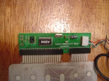
RPZAIR85031033
Dec 22, 2003Keyboard
Equipment Class
JBP - Part 15 Class B Computing Device Peripheral