RSNFLEX2GODual-Band Cellphone Signal Booster
Cellphone-Mate Inc. dba SureCall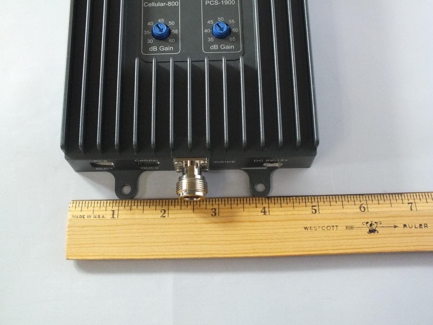
Click to zoom
Application Details
- Equipment Class
- B2W - Part 20 Wideband Consumer Booster (CMRS)
- Date of Grant
- Feb 24, 2014
- Application Purpose
- Original Equipment
- Date of Application
- Jan 16, 2014
- Equipment Note
- Dual-Band Cellphone Signal Booster
- Frequency Range
- 1930.00000000 - 1990.00000000
- Country
- United States
Documents & Files
Document Text
Text extracted from the exhibit documents filed with the FCC. Open a document above to read the original.
Users Manual
Dual-Band Wireless Adjustable Cellular Booster / Kit 3G Vehicle Cell Booster & Kit FLEX 2GO (CM-FLEX2GO) User Guide FLEX 2GO Kit for Vehicles INTRODUCTION 2 PRINCIPLES OF OPERATION 2 SURECALL FLEX 2GO PACKAGES 3 FLEX 2GO BOOSTER HARDWARE 4 PACKAGE CONTENTS 5 SITE SELECTION 5 INSTALLATION INSTRUCTIONS 6 TROUBLESHOOTING 9 SPECIFICATIONS 13 SAFETY INFORMATION 14 WARRANTY 15 INTRODUCTION Flex 2G Kit for vehicles (CM-FLEX2GO) SureCall, Inc. Page 2 All rights reserved. Introduction Congratulations on purchasing the SureCall Flex 2Go kit, the finest cellular amplifier available for your vehicle! SureCall adjustable cellular boosters and kits remove the frustration over dropped calls, limited range, and slow data rates by amplifying incoming and outgoing cellular signals in vehicles. The Flex 2Go is designed with leading-edge technologies to detect and amplify weak incoming signals your cellular device would otherwise miss and to broadcast a significantly stronger signal back to the cell tower. This guide contains all the information you need to get your SureCall Flex 2Go booster system up and running. Principles of Operation The SureCall Flex 2Go is a high-quality bidirectional amplifier that boosts cellular signals for cars, motorhomes, and other vehicles. The Flex 2Go works with two antennas: An inside antenna that communicates with your cell phone. An outside antenna that communicates with the cell tower. Signals sent from a cell tower are received by the outside antenna, amplified by the booster and then sent to your phone via the inside antenna. When your phone transmits, the signal is sent to the inside antenna, and then sent to the cell tower via the outside antenna. Some cell signal is required for the Flex 2Go to enhance cellular signal coverage. The weakest cell signal for the Flex 2Go to work is low -100dBm to high -90dBm. dBm is an abbreviation for the power ratio in decibels of the radio power per one milliwatt and indicates cell signal strength. INTRODUCTION Flex 2G Kit for vehicles (CM-FLEX2GO) SureCall, Inc. Page 3 All rights reserved. SureCall Flex 2Go Packages Package Package Contents CM-FLEX2GO 50dB booster with auto shutdown Magnetic mount antenna – CM200 Patch antenna with 12’ cord – CM110W DC car charger (18’cord) – for vehicle use Velcro ® and screw-mounting kit INTRODUCTION Flex 2G Kit for vehicles (CM-FLEX2GO) SureCall, Inc. Page 4 All rights reserved. Flex 2Go Booster Hardware The following figure shows the key hardware components on the Model CM-FLEX2GO cellular booster. Refer to this figure as you install your SureCall Flex 2Go. Outdoor Antenna Connector (not shown) Indoor Antenna Connector Power Connector Digital Interface PCS- 1900 Dial Alert LED Alert LED Cellular-800 Dial Digital Interface PACKAGE CONTENTS Flex 2G Kit for vehicles (CM-FLEX2GO) SureCall, Inc. Page 5 All rights reserved. Package Contents Unpack all package contents, compare them against the package contents list, and check for damage. For missing or damaged items, contact your reseller. Keep the carton and packing material to store the product or if you need to return it. Site Selection For optimum performance, select a location for your booster that: Is under the seat of the vehicle, for example. Is away from excessive heat, direct sunlight, or moisture. Has proper ventilation. INSTALLATION INSTRUCTIONS Flex 2G Kit for vehicles (CM-FLEX2GO) SureCall, Inc. Page 6 All rights reserved. Installation Instructions The Flex 2Go booster kit is suited for installation in a vehicle or motor home. Refer to the figure below when performing the following procedures. Step 1: Connect the Outside Antenna 1. Mount the magnetic antenna in a location that: Is on top of the vehicle. Has at least a 12-inch radius clear of obstructions and other radiating elements, such as a radio antenna. Is at least 4 - 6 feet from the inside antenna. 2. Using the supplied cable, connect the outside antenna to the booster connector marked OUTSIDE. 3. Run the outside antenna cord under front door insulation lining to hide and protect antenna cable. Wrap up any loose cable. 4. Hand tighten the connection. Note: The outside antenna must not be co-located or operating with any other antenna or booster. Step 2: Connect the Inside Antenna 1. Mount the inside antenna so it is: Within 2-3 feet of the cell phone for best results. Mounted on a surface that is at least 4” (10 cm) away from metal. INSTALLATION INSTRUCTIONS Flex 2G Kit for vehicles (CM-FLEX2GO) SureCall, Inc. Page 7 All rights reserved. 2. Using the supplied cable, connect the antenna to the booster connector marked INSIDE (see page 4). 3. Hand tighten the connection. Step 3: Mount the Booster 1. Select a location for your booster, such as under the driver’s seat. Step 4: Connect to DC Power 1. Connect the Power Cord. Connect the DC power cord to the booster before plugging it into the cigarette lighter adapter. Verify that all connections to the booster are tight and secure. 2. Turn the power switch on the lighter adapter to the ON position. The LED light glows, indicating that the booster is ready to use. The booster turns on automatically. The Power LED goes ON to show that the booster is ready for use (see page 4). If the Power LED does not go ON, be sure the DC outlet and adapter are working. INSTALLATION INSTRUCTIONS Flex 2G Kit for vehicles (CM-FLEX2GO) SureCall, Inc. Page 8 All rights reserved. If the red LED goes ON, it is the result of one of two factors. 1. More antenna separation is needed. Most likely, the easiest way to achieve this is to move the magnetic mount antenna farther to the back of vehicle away from the inside patch antenna. 2. Your vehicle is too close to a cell tower If unable to provide more antenna separation and the Alert LEDs flash after the initial activation period, lower the dial above the blinking LED by 5dB (for example, from 50 to 40) and monitor the bars on your cell phone to see whether reception has improved. The b…
Text truncated - open the document above for the full version.
Cover Letter(s)
48346 Milmont Drive Fremont, CA 94538 Phone: 510-770-0469 Fax: 510-996-7250 www.cellphone-mate.com FCC Authorization 18 th November, 2013 FEDERAL COMMUNICATIONS COMMISSIONS Authorization and Evaluation Division 7435 Oakland Mills Road Columbia, MD 21046 Subject: Agent Authorization To Whom It May Concern: We, Cellphone-mate, the undersigned, hereby authorize Compliance Testing, LLC to act on our behalf in all matters relating to application for Equipment authorization, including the signing of all documents relating to these matters. All acts carried out by Compliance Testing, LLC on our behalf shall have the same effect as our own action. We, the undersigned, hereby certify that we are not subject to a denial of federal benefits including FCC benefits, pursuant to Section 5301 of the Anti-Drug Abuse Act of 1988, 21 U.S.C. 853(a). This authorization is valid until further written notice from the applicant. Sincerely yours, Hongtao Zhan, CEO Cellphone-Mate Inc. 1888 365 6283 ext. 301
Cover Letter(s)
Page 1 of 2 FCC ID: RSNFLEX2GO IC ID: N/A CT Project: TCB-p1350026 From: John Erhard Date: December 13, 2013 1. The emissions types listed in the test report and users manual do not match. Please verify and correct as necessary. Cellphone-Mate – User’s Manual has been revised 2. Please add the final amplifier stage supply voltage and current to the block diagram. Both voltage and current is required. Cellphone-Mate – Block Diagram has been revised 3. Replacing resistors of other components as part of a tune up procedure is not allowed. The production product is required to match the schematic. Variations of components in the TX circuit path require separate FCC IDs. Please verify this procedure. Cellphone-Mate – Updated 4. The block diagram does not indicate which frequency bands are used with each of the filter / amplifier paths. Please add a table indicating this information. Cellphone-Mate – Table has been added 5. The block diagram and the schematics do not consistently name the paths, the block diagram call them PCS and CDMA which the schematic calls them PCS and cellular. Please correct. Cellphone-Mate – Documents have been revised to use consistent naming conventions 6. Internal photos are required to have all shields removed. Please remove the shields at the antenna terminals and submit new photos. Cellphone-Mate – Additional photos have been taken 7. External photos showing all sides of the final product are required. Please add additional photos showing the rest of the product. Cellphone-Mate – Additional photos have been taken Page 2 of 2 8. Spectrum analyzer plots throughout the test report do not show the 1:3 RBW / VBW ration required. As this spectrum analyzer only indicates the RBW and a checkbox for VBW please explain how the requirement is met. CT – When the checkbox for the VBW is not checked, the video bandwidth is disabled. Per the manufacturers user manual this is the correct setting for meeting the requirement that the VBW is set to 3x the RBW. The explanation provided below is copied from the Tektronix RSA 5126 Real Time Spectrum Analyzer user’s manual. Page 120 of the RSA 5126 User’s manual “The VBW setting enables/disables the Video Bandwidth filter. VBW is used in traditional swept analyzers to reduce the effect of noise on the displayed signal. The VBW algorithm in the analyzer emulates the VBW filters of traditional swept analyzers. The maximum VBW value is the current RBW setting. The minimum VBW value is 1/10,000 of the RBW setting. VBW is disabled when the Filter shape is set to CISPR. NOTE. If you are following a procedure that says to "set VBW to three times the RBW value or greater", it means that the test should be conducted with no VBW effects. In the analyzer, this condition is met by disabling the VBW function.” 9. Page 38 of the test report has an incorrect limit for the 1850 – 1910 uplink band. Please correct. CT – Limit has been corrected. 10. Page 39 has incorrect noise limits and margins. It also appears that a few of the measurements may be out of compliance. Please correct. CT – The limits have been corrected and new data was recorded. Incorrect limits were used and there was an offset in the spectrum analyzer from the previous test that shifted all the data by ~ 6 dB higher that it actually was. 11. Page 61 of the test report has the downlink restart time limit and measurement units listed as mS; this should be in seconds. CT – Units have been corrected 12. In the MSCL document, there is no limit on MSCL. Please remove and/or explain where this limit is derived. Cellphone-Mate – MSCL document has been revised 13. Please explain where the MSCL space loss is derived. Cellphone-Mate – MSCL Space Loss Explanation document has been supplied 14. In the MPE report please provide the formulas for calculating the non-log values for the antenna and cable numeric values. Cellphone-Mate – Calculations have been added Response by: Greg Corbin & Cellphone-Mate Submitted by: Amanda Reed Date: 12/18/2013
Cover Letter(s)
Page 1 of 1 FCC ID: RSNFLEX2GO IC ID: N/A CT Project: TCB-p1370007 From: John Erhard Date: January 2, 2014 1. Please correct the final amplifier stage supply voltage and current to the block diagram to be the amplified current not the quiescent current. The maximum capable values are required. Cellphone-Mate - Updated Block Diagram has been provided 2. The limit is still in the MSCL document with no explanation. Please explain where this limit originates or remove it from the document. Cellphone-Mate - Updated MSCL document has been provided Response by: Cellphone-Mate Submitted by: Amanda Reed Date: 1/3/2014
Cover Letter(s)
48346 Milmont Drive Fremont, CA 94538 Phone: 510-770-0469 Fax: 510-996-7250 www.cellphone-mate.com FCC Confidential Authorization 20th January, 2014 FEDERAL COMMUNICATIONS COMMISSIONS Authorization and Evaluation Division 7435 Oakland Mills Road Columbia, MD 21046 Subject: Confidentiality Request regarding application for certification of FCC ID: RSNFLEX2GO In accordance with Sections 0.457 and 0.459 of the Commission’s Rules, Cellphone-mate hereby requests long- term confidential treatment of information accompanying this application as outlined below: Block Diagram Schematics Operation Description Parts list The above materials contain proprietary and confidential information not customarily released to the public. The public disclosure of these materials provides unjustified benefits to its competitors in the market. Sincerely, Sincerely Yours, Hongtao Zhan, CEO Cellphone-Mate Inc. 1888 365 6283 ext. 301
External Photos
External Photos Cellphone Mate, LLC FCC ID: RSNFLEX2GO Model: CM Flex2go Page 1 of 8 External Photos Cellphone Mate, LLC FCC ID: RSNFLEX2GO Model: CM Flex2go Page 2 of 8 External Photos Cellphone Mate, LLC FCC ID: RSNFLEX2GO Model: CM Flex2go Page 3 of 8 External Photos Cellphone Mate, LLC FCC ID: RSNFLEX2GO Model: CM Flex2go Page 4 of 8 External Photos Cellphone Mate, LLC FCC ID: RSNFLEX2GO Model: CM Flex2go Page 5 of 8 External Photos Cellphone Mate, LLC FCC ID: RSNFLEX2GO Model: CM Flex2go Page 6 of 8 External Photos Cellphone Mate, LLC FCC ID: RSNFLEX2GO Model: CM Flex2go Page 7 of 8 External Photos Cellphone Mate, LLC FCC ID: RSNFLEX2GO Model: CM Flex2go Page 8 of 8
ID Label/Location Info
2G-3G Mobile Cellular Booster Frequency Band: 824-894 MHz [Cellular Band] 1850-1990 MHz [PCS Band] Gain: 30 - 50dB [ Cellular / PCS ] Maximum Output Power: 1W ERIP FCC ID: RSNFLEX2GO [50dB Dual Band Adjustable] www.surecall.com 1-888-365-MATE [6283] Assembled in China For Personal Use www.surecall.com 1-888-365-MATE [6283] Assembled in China Frequency Band: 824-894 MHz [Cellular Band] 1850-1990 MHz [PCS Band] Gain: 35 - 65dB [ Cellular / PCS ] Maximum Output Power: 1W ERIP FCC ID: RSNFLEXPRO 2G-3G In-Building Cellular Booster [ 65dB Dual Band Adjustable ] For Personal Use
Internal Photos
Internal Photos Cellphone Mate, LLC FCC ID: RSNFLEX2GO Model: CM Flex2go Page 1 of 8 Internal Photos Cellphone Mate, LLC FCC ID: RSNFLEX2GO Model: CM Flex2go Page 2 of 8 Internal Photos Cellphone Mate, LLC FCC ID: RSNFLEX2GO Model: CM Flex2go Page 3 of 8 Internal Photos Cellphone Mate, LLC FCC ID: RSNFLEX2GO Model: CM Flex2go Page 4 of 8 Internal Photos Cellphone Mate, LLC FCC ID: RSNFLEX2GO Model: CM Flex2go Page 5 of 8 Internal Photos Cellphone Mate, LLC FCC ID: RSNFLEX2GO Model: CM Flex2go Page 6 of 8 Internal Photos Cellphone Mate, LLC FCC ID: RSNFLEX2GO Model: CM Flex2go Page 7 of 8 Internal Photos Cellphone Mate, LLC FCC ID: RSNFLEX2GO Model: CM Flex2go Page 8 of 8
RF Exposure Info
1 48346 Milmont Dr., Fremont, CA 94538 Phone: 510-770-0469 Fax: 510-996-7250 www.surecall.com Antenna Kitting Information Flex2go Vehicle Kit Component Prod No. Description Gain/Loss Notes 800MHz 1900MHz Outdoor Antenna CM200 3dBi 5dBi Outdoor Cable CM174-10FT 10Feet 4.3dB 8.8dB Indoor Antenna CM110W 1.1dBi 3dBi Indoor Cable CM174-10FT 10Feet 4.3dB 8.8dB Marine Kit Component Prod No. Description Gain/Loss Notes 800MHz 1900MHz Outdoor Antenna CM288W or Galaxy 5412-P 3dBi 4dBi Outdoor Cable CM240-40FN 40Feet 3.98dB 6.52dB Indoor Antenna CM248W 7dBi 10dBi Indoor Cable CM240-20FN 20Feet 2.29dB 3.56dB Desk top/RV Kit Component Prod No. Description Gain/Loss Notes 800MHz 1900MHz Outdoor Antenna CM288W 3dBi 4dBi Outdoor Cable CM240-40FN 40Feet 3.98dB 6.52dB Indoor Antenna CM120W 1.2dBi 3dBi
RF Exposure Info
EIRP Calculations Flex2go 1 Vehicle Kit: Vehicle Kit Component Outdoor Antenna KIT Antenna:CM200 Cable:CM174 -10FT 10Feet Outdoor Antenna Gain Outdoor Cable Loss At 1900MHz(dBi) At 800MHz(dBi) At 1900MHz(dB) At 800MHz(dB) 5 3 8.8 4.3 Indoor Patch Antenna KIT Antenna:CM110W Cable: CM174 -10FT 10Feet Indoor Antenna Gain Indoor Cable Loss At 1900MHz(dBi) At 800MHz(dBi) At 1900MHz(dB) At 800MHz(dB) 3 1.1 8.8 4.3 EIRP Calculations of Mobile booster Flex2go Pulse GSM Frequency Output Power(dBm) Outdoor Antenna Gain(dBi) Outdoor Cable Loss(dB) EIRP (dBm) Limit (dBm) UL 1850-1915 23.6 5 8.8 19.8 30 UL 824-849 22.0 3 4.3 20.7 30 Frequency Output Power(dBm) Indoor Antenna Gain(dBi) Indoor Cable Loss(dB) EIRP(d Bm) Limit(dB m) DL 1930-1995 -4.7 3 8.8 -10.5 17 DL 869-894 -5.1 1.1 4.3 -8.3 17 4.1MHz AWGN Frequency Output Power(dBm) Outdoor Antenna Gain(dBi) Outdoor Cable Loss(dB) EIRP(d Bm) Limit(dB m) UL 1850-1915 19.6 5 8.8 15.8 30 UL 824-849 20.0 3 4.3 18.7 30 Frequency Output Power(dBm) Indoor Antenna Gain(dBi) Indoor Cable Loss(dB) EIRP(d Bm) Limit(dB m) DL 1930-1995 -6.6 3 8.8 -12.4 17 DL 869-894 -6.5 1.1 4.3 -9.7 17 2 Marine Kit: Marine Kit Component Outdoor Antenna KIT Antenna:CM288W or Galaxy 5412-P Cable:CM240 -40FN 40Feet Outdoor Antenna Gain Outdoor Cable Loss At 1900MHz(dBi) At 800MHz(dBi) At 1900MHz(dB) At 800MHz(dB) 4 3 6.52 3.98 Indoor Panel Antenna KIT Antenna:CM248W Cable:CM240 -20FN 20Feet Indoor Antenna Gain Indoor Cable Loss At 1900MHz(dBi) At 800MHz(dBi) At 1900MHz(dB) At 800MHz(dB) 10 7 3.56 2.29 EIRP Calculations of Mobile booster Flex2go Pulse GSM Frequency Output Power(dBm) Outdoor Antenna Gain(dBi) Outdoor Cable Loss(dB) EIRP (dBm) Limit (dBm) UL 1850-1915 23.6 4 6.52 21.1 30 UL 824-849 22.0 3 3.98 21.0 30 Frequency Output Power(dBm) Outdoor Antenna Gain(dBi) Outdoor Cable Loss(dB) EIRP (dBm) Limit (dBm) DL 1930-1995 -4.7 10 3.56 1.7 17 DL 869-894 -5.1 7 2.29 -0.4 17 4.1MHz AWGN Frequency Output Power(dBm) Outdoor Antenna Gain(dBi) Outdoor Cable Loss(dB) EIRP (dBm) Limit (dBm) UL 1850-1915 19.6 4 6.52 17.1 30 UL 824-849 20.0 3 3.98 19.0 30 Frequency Output Power(dBm) Outdoor Antenna Gain(dBi) Outdoor Cable Loss(dB) EIRP (dBm) Limit (dBm) DL 1930-1995 -6.6 10 3.56 -0.2 17 DL 869-894 -6.5 7 2.29 -1.8 17 3 Desk top/RV kit: Desk top/RV Kit Component Outdoor Antenna KIT Antenna:CM288W Cable:CM240 -40FN 40Feet Outdoor Antenna Gain Outdoor Cable Loss At 1900MHz(dBi) At 800MHz(dBi) At 1900MHz(dB) At 800MHz(dB) 4 3 6.52 3.98 Indoor Right Angle Antenna KIT Antenna:CM120W Cable: NO Indoor Antenna Gain Indoor Cable Loss(connector IL) At 1900MHz(dBi) At 800MHz(dBi) At 1900MHz(dB) At 800MHz(dB) 3 1.2 0.3 0.3 EIRP Calculations of Mobile booster Flex2go Pulse GSM Frequency Output Power (dBm) Outdoor Antenna Gain(dBi) Outdoor Cable Loss(dB) EIRP (dBm) Limit (dBm) UL 1850-1915 23.6 4 6.52 21.1 30 UL 824-849 22.0 3 3.98 21.0 30 Frequency Output Power(dBm) Outdoor Antenna Gain(dBi) Outdoor Cable Loss(dB) EIRP (dBm) Limit (dBm) DL 1930-1995 -4.7 3 0.3 -2.0 17 DL 869-894 -5.1 1.2 0.3 -4.2 17 4.1MHz AWGN Frequency Output Power(dBm) Outdoor Antenna Gain(dBi) Outdoor Cable Loss(dB) EIRP (dBm) Limit (dBm) UL 1850-1915 19.6 4 6.52 17.1 30 UL 824-849 20.0 3 3.98 19.0 30 Frequency Output Power(dBm) Outdoor Antenna Gain(dBi) Outdoor Cable Loss(dB) EIRP (dBm) Limit (dBm) DL 1930-1995 -6.6 3 0.3 -3.9 17 DL 869-894 -6.5 1.2 0.3 -5.6 17
RF Exposure Info
1 FCC§1.1307(b)(1)&§2.1091-RF EXPOSURE 1.1 Applicable Standard According to§1.1310 and §2.1091(Mobile Devices)RF exposure is calculated. Limits for General Population/Uncontrolled Exposure Frequency Range (MHz) Power Density (mW/cm²) Limits for General Population/Uncontrolled Exposure 0.3-1.34 *(100) 1.34-30 *(180/f²) 30-300 0.2 300–1,500 f/1500 1,500–100,000 1 Note: f= frequency in MHz *=Plane-wave equivalent power density 1.2 MPE Prediction 1.2.1 Calculation of MPE at 20 cm distance, Equation from OET Bulletin 65, Edition 97-01 S=PG/4πR² Where: S=power density P=power input to antenna G= maximum power gain of the antenna in the direction of interest relative to an isotropic radiator, subtract antenna’s cable loss, (result is in numeric form) R=distance to the center of radiation of the antenna (20cm in the following calculation) 1.2.2 Calculation formula of G(numeric ) G (numeric)=10 {Maximum Antenna Gain dBi () -Cable LossdB () } 1 10 Where: G(numeric)= Maximum power gain of the antenna in the direction of interest relative to an isotropic radiator, subtract antenna’s cable loss, (result is converted from decibel into numeric form with above equation) 1.3 Test Result 1.3.1 Under the conditions of Vehicle Kit Component(Antenna KIT) Vehicle Kit Component Outdoor Antenna KIT Antenna:CM200 Cable:CM174 -10FT 10Feet Outdoor Antenna Gain Outdoor Cable Loss At 1900MHz(dBi) At 800MHz(dBi) At 1900MHz(dB) At 800MHz(dB) 5 3 8.8 4.3 Indoor Patch Antenna KIT Antenna:CM110W Cable: CM174 -10FT 10Feet Indoor Antenna Gain Indoor Cable Loss At 1900MHz(dBi) At 800MHz(dBi) At 1900MHz(dB) At 800MHz(dB) 3 1.1 8.8 4.3 Cellular Band UL: Maximum peak output power at antenna input terminal(dBm): 22.00 Maximum peak output power at antenna input terminal(mW): 158.49 Prediction distance(cm): 20 Prediction frequency(MHz): 829.82 Maximum Antenna Gain (dBi): 3 Cable Loss(dB): 4.3 G(numeric): 0.74 Power density at predication frequency and distance(mW/cm²): 0.0234 MPE limit for uncontrolled exposure at predication frequency(mW/cm²): 0.5532 Cellular Band DL: Maximum peak output power at antenna input terminal(dBm): -5.10 Maximum peak output power at antenna input terminal(mW): 0.31 Prediction distance(cm): 20 Prediction frequency(MHz): 879.38 Maximum Antenna Gain (dBi): 1.1 Cable Loss(dB): 4.3 G(numeric): 0.48 Power density at predication frequency and distance(mW/cm²): 0.00003 MPE limit for uncontrolled exposure at predication frequency(mW/cm²): 0.5863 PCS Band UL: Maximum peak output power at antenna input terminal(dBm): 23.60 Maximum peak output power at antenna input terminal(mW): 229.09 Prediction distance(cm): 20 Prediction frequency(MHz): 1861.15 Maximum Antenna Gain (dBi): 5 Cable Loss(dB): 8.8 G(numeric): 0.42 Power density at predication frequency and distance(mW/cm²): 0.0190 MPE limit for uncontrolled exposure at predication frequency(mW/cm²): 1.0000 PCS Band DL: Maximum peak output power at antenna input terminal(dBm): -4.70 Maximum peak output power at antenna input terminal(mW): 0.34 Prediction distance(cm): 20 Prediction frequency(MHz): 1960.98 Maximum Antenna Gain (dBi): 3 Cable Loss(dB): 8.8 G(numeric): 0.26 Power density at predication frequency and distance(mW/cm²): 0.00002 MPE limit for uncontrolled exposure at predication frequency(mW/cm²): 1.0000 1.3.2 Under the conditions of Marine Kit Component Component (Antenna KIT) Marine Kit Component Outdoor Antenna KIT Antenna:CM288W or Galaxy 5412-P Cable:CM240 -40FN 40Feet Outdoor Antenna Gain Outdoor Cable Loss At 1900MHz(dBi) At 800MHz(dBi) At 1900MHz(dB) At 800MHz(dB) 4 3 6.52 3.98 Indoor Panel Antenna KIT Antenna:CM248W Cable:CM240 -20FN 20Feet Indoor Antenna Gain Indoor Cable Loss At 1900MHz(dBi) At 800MHz(dBi) At 1900MHz(dB) At 800MHz(dB) 10 7 3.56 2.29 Cellular Band UL: Maximum peak output power at antenna input terminal(dBm): 22.00 Maximum peak output power at antenna input terminal(mW): 158.49 Prediction distance(cm): 20 Prediction frequency(MHz): 829.82 Maximum Antenna Gain (dBi): 3 Cable Loss(dB): 3.98 G(numeric): 0.80 Power density at predication frequency and distance(mW/cm²): 0.0252 MPE limit for uncontrolled exposure at predication frequency(mW/cm²): 0.5532 Cellular Band DL: Maximum peak output power at antenna input terminal(dBm): -5.10 Maximum peak output power at antenna input terminal(mW): 0.31 Prediction distance(cm): 20 Prediction frequency(MHz): 879.38 Maximum Antenna Gain (dBi): 7 Cable Loss(dB): 2.29 G(numeric): 2.96 Power density at predication frequency and distance(mW/cm²): 0.0002 MPE limit for uncontrolled exposure at predication frequency(mW/cm²): 0.5863 PCS Band UL: Maximum peak output power at antenna input terminal(dBm): 23.60 Maximum peak output power at antenna input terminal(mW): 229.09 Prediction distance(cm): 20 Prediction frequency(MHz): 1861.15 Maximum Antenna Gain (dBi): 4 Cable Loss(dB): 6.52 G(numeric): 0.56 Power density at predication frequency and distance(mW/cm²): 0.0255 MPE limit for uncontrolled exposure at predication frequency(mW/cm²): 1.0000 PCS Band DL: Maximum peak output power at antenna input terminal(dBm): -4.70 Maximum peak output power at antenna input terminal(mW): 0.34 Prediction distance(cm): 20 Prediction frequency(MHz): 1960.98 Maximum Antenna Gain (dBi): 10 Cable Loss(dB): 3.56 G(numeric): 4.41 Power density at predication frequency and distance(mW/cm²): 0.0003 MPE limit for uncontrolled exposure at predication frequency(mW/cm²): 1.0000 1.3.3 Under the conditions of Desk top/RV Kit Component (Antenna KIT) Desk top/RV Kit Component Outdoor Antenna KIT Antenna:CM288W Cable:CM240 -40FN 40Feet Outdoor Antenna Gain Outdoor Cable Loss At 1900MHz(dBi) At 800MHz(dBi) At 1900MHz(dB) At 800MHz(dB) 4 3 6.52 3.98 Indoor Right Angle Antenna KIT Antenna:CM120W Cable: NO Indoor Antenna Gain Indoor Cable Loss(Connector IL) At 1900MHz(dBi) At 800MHz(dBi) At 1900MHz(dB) At 800MHz(dB) 3 1.2 0.3 0.3 Cellular Band UL: Maximum peak output power at antenna input terminal(dBm): 22.00 Maximum peak output power at an…
Text truncated - open the document above for the full version.
RF Exposure Info
48346 Milmont Drive Fremont, CA 94538 Phone: 510-770-0469 Fax: 510-996-7250 www.surecall.com 1 Explanation of MSCL Mobile antenna Booster server antenna Mobile Booster MSCL Indoor Cable Loss Path loss Mobile Antenna Gain Indoor Antenna Gain spatial distance=d Figure 1 MSCL= Path loss + Indoor Cable Loss - Mobile Antenna Gain- Indoor Antenna Gain......① 1.1 Decibel version of free-space propagation loss equation Path loss (dB) =20Lgf+20Lgd+32.45 ......② or Path loss (dB) =20Lgf+20LgD-27.55 ......③ f (MHz), d (km), D(m) , d=1000D 1.1.1 Operation Frequency At PCS (1850-1910MHz) f =1850MHz At Cellular (824-849MHz) f =824 MHz 48346 Milmont Drive Fremont, CA 94538 Phone: 510-770-0469 Fax: 510-996-7250 www.surecall.com 1.1.2 Minimum Separation Distances for MSCL base on FCC new rule D (m) Minimum Separation Distances for MSCL Calculation or Measurements D(m) Indoor server antenna types Minimum separation distances D (m) Ceiling Mounted (i.e., Dome-type) Antennas 2.0 Wall Mounted (i.e., Panel or other type) Antennas 1.0 or 2.0* Table Top Antennas 1.0 * Note: Wall Mounted (i.e., Panel or other type) Antennas: Alternatively, if a manufacturer clearly specifies a minimum separation distance to consumer devices in the installation manual or other user documentation provided with the booster, a reasonable minimum separation distance could be up to 6 feet (or 2 meters) horizontally removed from the antenna. In this case, the user would be required to ensure this minimum separation distance for all CMRS devices authorized for use with this booster. 1.2 Mobile Antenna Gain Mobile Antenna Gain=0dBi 1.3 Indoor Cable Loss And Indoor Antenna Gain Indoor Cable Loss and Indoor Antenna Gain are listed in the separate submitted file of Flex2go Antenna Kitting . 48346 Milmont Drive Fremont, CA 94538 Phone: 510-770-0469 Fax: 510-996-7250 www.surecall.com 2 MSCL Calculations Flex2go 2.1 Vehicle Kit : Path loss =20Lgf+20LgD-27.55 Operation Frequency (MHz) f(MHz) D(m) Constant(dB) Path loss(dB) PCS(1850-1910) 1850 0.4 27.55 29.8 Cellular(824-849) 824 0.4 27.55 22.8 MSCL Operation Frequency (MHz) Path loss (dB) Indoor Antenna Gain(dBi) Indoor Cable Loss(dB) MSCL(dB) PCS (1850-1910) 29.8 3 8.8 35.6 Cellular (824-849) 22.8 1.1 4.3 26.0 2.2 Marine Kit: Path loss=20Lgf+20LgD-27.55 Operation Frequency (MHz) f(MHz) D(m) Constant(dB) Path loss(dB) PCS(1850-1910) 1850 0.9 27.55 36.9 Cellular(824-849) 824 0.9 27.55 29.8 MSCL Operation Frequency (MHz) Path loss (dB) Indoor Antenna Gain(dBi) Indoor Cable Loss(dB) MSCL(dB) PCS (1850-1910) 36.9 10 3.56 30.4 Cellular (824-849) 29.8 7 2.29 25.1 2.3 Desk top/RV kit: Path loss=20Lgf+20LgD-27.55 Operation Frequency (MHz) f(MHz) D(m) Constant(dB) Path loss(dB) PCS(1850-1910) 1850 0.6 27.55 33.3 Cellular(824-849) 824 0.6 27.55 26.3 MSCL Operation Frequency (MHz) Path loss (dB) Indoor Antenna Gain(dBi) Indoor Cable Loss(dB) MSCL(dB) PCS (1850-1910) 33.3 3 0.3 30.6 Cellular (824-849) 26.3 1.2 0.3 25.4 48346 Milmont Drive Fremont, CA 94538 Phone: 510-770-0469 Fax: 510-996-7250 www.surecall.com
Test Report
p1370007_FCC_Part 20_Rev 4.0 Page 1 of 70 Test Report Prepared for: Cellphone-Mate Inc. Model: CM Flex2go Description: Dual-Band Cellphone Signal Booster FCC ID: RSNFlex2go To FCC Part 20 Date of Issue: October 16, 2013 On the behalf of the applicant: Cellphone-Mate Inc. 48346 Milmont Drive Fremont, CA 94538 To the attention of: Dennis Findley, Lead Tech Support Ph: (510) 770-0469 Email: [email protected] Prepared By Compliance Testing, LLC 3356 N San Marcos Pl, Suite 107 Chandler, AZ 85225-7176 (866) 311-3268 phone / (480) 926-3598 fax www.compliancetesting.com Project No: p1370007 Greg Corbin Project Test Engineer This report may not be reproduced, except in full, without written permission from Compliance Testing All results contained herein relate only to the sample tested p1370007_FCC_Part 20_Rev 4.0 Page 2 of 70 Test Report Revision History Revision Date Revised By Reason for Revision 1.0 October 16, 2013 Greg Corbin Original Document 2.0 November 21, 2013 Greg Corbin Manufacturer changed MSCL, updated variable gain tables with new MSCL page 46 3.0 December 16, 2013 Greg Corbin Corrected limit on page 38, data error in tables on page 39, and measurements units on page 61. 4.0 January 3, 2014 Greg Corbin Corrected MSCL in the variable gain tables on page 46 to match final MSCL document submitted by manufacturer. p1370007_FCC_Part 20_Rev 4.0 Page 3 of 70 Table of Contents Description Page Standard Test Conditions and Engineering Practices 5 Test Result Summary 6 Authorized Frequency Band 7 Maximum Power and Gain 10 Intermodulation 12 Out-of-Band Emissions 15 Conducted Spurious Emissions 30 Noise Limits 37 Uplink Inactivity 43 Variable Gain 45 Occupied Bandwidth 47 Oscillation Detection 60 Radiated Spurious 68 Test Equipment Utilized 70 p1370007_FCC_Part 20_Rev 4.0 Page 4 of 70 ILAC / A2LA Compliance Testing, LLC, has been accredited in accordance with the recognized International Standard ISO/IEC 17025:2005. This accreditation demonstrates technical competence for a defined scope and the operation of a laboratory quality management system (refer joint ISO-ILAC-IAF Communiqué dated January 2009) The tests results contained within this test report all fall within our scope of accreditation, unless noted below. Please refer to http://www.compliancet…
Text truncated - open the document above for the full version.
Contact Information
Applicant
Dennis Findley(Director of Operations)
Test Firm
Compliance Testing, LLCMichael Schafer
Technical Specifications
| # | Rule Parts | Frequency Range | Power Output | Emission |
|---|---|---|---|---|
| 16 | 24E | 1.93 GHz - 1.99 GHz | 339.00 µW | G7W |
Other Applications from Cellphone-Mate Inc. dba SureCall

RSNF4H-MAX
Jun 29, 2021Dual Enclosure Wideband Consumer booster Roof top unit
Equipment Class
B2W - Part 20 Wideband Consumer Booster (CMRS)
RSNF4H-MAXS
Jun 29, 2021Dual Enclosure Wideband Consumer booster Indoor unit
Equipment Class
B2W - Part 20 Wideband Consumer Booster (CMRS)
RSNPSBG-2BUL
Mar 03, 2021In-building 2-Way Emergency Radio Communication Enhancement booster
Equipment Class
B9B - Part 90 Class B Industrial Booster (non-SMR)
RSNFLARE-DB
Aug 04, 2020Dual Band Booster
Equipment Class
B2W - Part 20 Wideband Consumer Booster (CMRS)
RSNLTE-V
Jun 25, 2020Quad Band Signal Booster
Equipment Class
B2W - Part 20 Wideband Consumer Booster (CMRS)