RSNFORCE-550Consumer Booster
Cellphone-Mate Inc. dba SureCall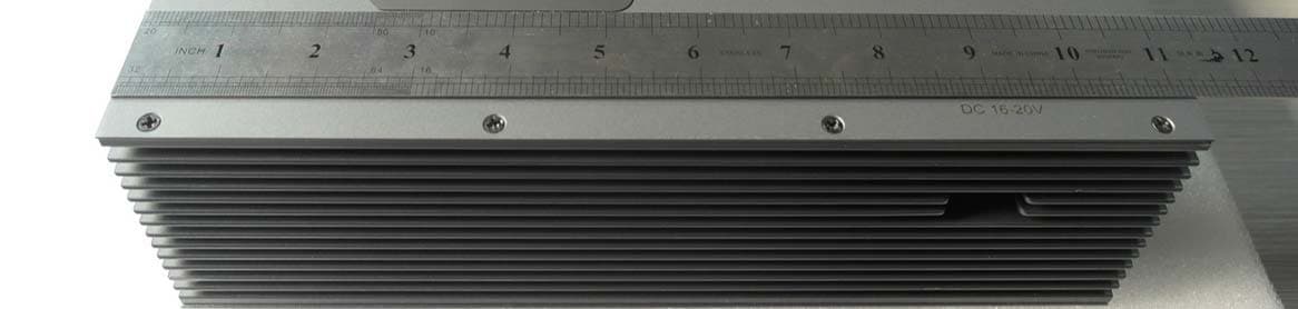
Click to zoom
Application Details
- Equipment Class
- B2W - Part 20 Wideband Consumer Booster (CMRS)
- Date of Grant
- Aug 20, 2014
- Application Purpose
- Original Equipment
- Date of Application
- Aug 03, 2014
- Equipment Note
- Consumer Booster
- Frequency Range
- 2110.00000000 - 2155.00000000
- Country
- United States
Documents & Files
Document Text
Text extracted from the exhibit documents filed with the FCC. Open a document above to read the original.
Users Manual
Force5-50 2G-3G-4G 5-Band Wireless Adjustable Cellular Booster Kit User Guide Introduction Installation Packages Contents Configuring Gain Setting Introduction Troubleshooting Theory of Operation Quick Install Guide Booster Hardware Installation Steps Theory of Operation Safety Information 2 INTRODUCTION Thank you for your purchase of the Force5-50. The Force5-50 5-Band adjustable cellular signal booster removes the frustration over dropped calls, limited range and slow data rates by amplifying incoming and outgoing cellu- lar signals in large watercraft. The Force5-50 enhances 2G, 3G and 4G data reception data for all major US. Carriers. This guide contains all the information you’ll need to get your Force5-50 booster system up and running. If you need any assistance while installing this product please contact tech support at 1-888-365-6283 or email us at: [email protected]. BEFORE USE, you MUST REGISTER THIS DEVICE with your wireless provider and have your provider’s consent. Most wireless providers consent to the use of this device on their network. If you are unsure, contact your provider. How it works The Force5-50 is a high-quality bidirectional signal booster that enhances signals to areas that are prone to weak cellular coverage. Force5-50 works with two or more antennas: • up to four inside antennas that communicate with your cellphone. • an outside antenna that communicates with cellular towers. Signals sent from a cellular tower are received by the outside antenna, ampli- fied by the booster and then broadcast to your phone via the inside antenna. When your phone transmits, the signal is sent to the inside antenna, amplified and then sent to the cell tower via the outside antenna. The signal booster requires a minimum cellular signal of low -100 dBm to high -90 dBm. Signal readings usually appear as a negative number. The stronger the signal, the closer it gets to zero. Signals stronger than -50dB may cause the booster to temporarily shut down. To measure your existing cellular signal on an Apple iPhone, dial *3001#12345# and press Call. In the top-left corner, your dB number appears instead of bars. For Android devices, you can download several apps to measure exact signal strength. In your phone’s App Store, search for “check signal strength” to find a cell signal measurement app. 3 INTRODUCTION Package Contents: Unpack all package contents, compare them against the package contents list, and check for damage. For missing or damaged items, contact your retailer. Keep the carton and packing material to store the product or if you need to return it. The following image shows the key hardware components on the cellular booster. Refer to this image as you install your Force5-50 components. BoosterOutside Antenna with mount Inside Antenna with bracket Cable-20’ and 40’ Phantom Package Contents 50 dB adjustable booster (2) SC174 10 foot cables SC-110W inside antenna SC-200 outside antenna 248W-M inside panel antenna 18V DC power supply Screws not supplied* Please purchase separately. 4 Quick Install Guide Installation The Force5-50 booster kit is specially designed for marine applications. It can also be used for other applications with the right antennas, cables and mounting hardware. Step 1. Connect the SC-200 Outside Antenna The SC-200 is a, full-band antenna, ideal for marine use. Option 1 (Recommended) 1. Choose a mounting location that is as high as possible, free from obstructions and as far as possible from other antennas and sources of RF signal. 2. Before mounting base, drill a hole in the middle of the mounting location wide enough in diameter to allow SC-174 cable with FME connector to go through. 3. Hand-tighten the antenna base to the ferrule. 4. Feed cable, N connector end first, through bottom of base and through hollowferrule. 5. Hand-tighten N connector to outside antenna and antenna to ferrule. 6. Feed cable, FME end first through the drilled hole. 7. Mount base (screws not provided) and hand tighten ferrule to mount base. INSTALLATION 5 Option 2 1. When location of outside antenna has been determined, remove cap from ferrule side hole. 2. Feed FME connector (small end) and cable through side hole on the f shown in the figure below. 3. Feed remainder of cable through ferrule hole until approximately 1” of cable remains. 4. Connect N connector to antenna. 5. Screw antenna onto ferrule, bend cable to prevent cable from twisting. 6. Screw base onto other end of ferrule. 7. Mount base onto location. INSTALLATION 1 2 1 2 FME connector 1 2 N connector 3 6 Step 2. Using the SC-174 cable Use the SC-174 cable FME connector to connect the outside antenna to the boost connector marked OUTSIDE (see page 3). Make sure to not coil additional coax cable that might be left over from installa- tion. Hand tighten the connection. Before installing Indoor Antenna check the table below for optimum coverage. Step 3. Connect the Interior Antenna Option 1: Standard Wireless Usage (Recommended) The supplied SC-110W full-band antenna is a compact directional antenna de- signed to cover 2G, 3G, 4G and WLAN systems for Cellular, PCS, AWS and LTE frequencies. It’s a high-gain indoor antenna suited for places where the signal needs to be broadcast over a wide area. This interior antenna transmits and receives signals to cell phones. 1. Choose location for mounting antenna on vertical surface. Ideal height from the cabin floor (should be approximate height of cell phone users). Note: As you can see from the table above, acquiring the recommended inside and outside antenna separation optimizes coverage significantly. Panel antenna can be vertically installed 6 ft. under outside antenna with the booster at full dB gain. Inside panel antenna should face away from outside antenna. If panel antenna faces outside antenna, the booster will oscillate and go into Auto Shutdown. Required Between Outside and Inside Antenna antenna separation • 50dB 8-10 ft. separation • 47dB 5-7 ft. separation • 44d…
Text truncated - open the document above for the full version.
Cover Letter(s)
48346 Milmont Drive Fremont, CA 94538 Phone: 510-770-0469 Fax: 510-996-7250 www.cellphone-mate.com FCC Confidential Authorization 17 th July, 2014 FEDERAL COMMUNICATIONS COMMISSIONS Authorization and Evaluation Division 7435 Oakland Mills Road Columbia, MD 21046 Subject: Confidentiality Request regarding application for certification of FCC ID: RSNFORCE-550 In accordance with Sections 0.457 and 0.459 of the Commission’s Rules, Cellphone-mate hereby requests long- term confidential treatment of information accompanying this application as outlined below: Block Diagram Schematics Operation Description Parts list The above materials contain proprietary and confidential information not customarily released to the public. The public disclosure of these materials provides unjustified benefits to its competitors in the market. Sincerely, Sincerely Yours, Hongtao Zhan, CEO Cellphone-Mate Inc. 1888 365 6283 ext. 301
Cover Letter(s)
Page 1 of 1 FCC ID: RSNFORCE-550 IC ID: CT Project: p1440011 From: Shawn McMillen Date: 07/28/2014 1-Please note that the FCC ID on the 731 form is incorrect. Should not contain an additional dash. DW- Corrected. 2-The plots provided on pages7 thru 12 in the EMC are very difficult to read. May want to consider reformatting them. MG – We will try to use a higher resolution next time for the plots. In the interim, people have used the zoom function to view these. 3-Page 3 of the user’s manual lists 2 x SC174 10’ cables however the picture shows a 20’ and 40’ cable. Just for noting purposes, no action is necessary. DW-Notified customer. 4-The table on page 13 of the user’s manual lists the maximum gain as being 72dB. Is this correct? DW-Customer fixed. Revised manual saved. CT - Response by: Submitted by: Date:
ID Label/Location Info
Frequency Band: 1850-1915 MHz / 1930-1995 MHz 1710-1755 MHz / 2110-2155 MHz 824-849 MHz / 869-894 MHz 698-716 MHz / 728-746 MHz 776-787 MHz / 746-757 MHz This device complies with part 15 of the FCC Rules. Operation is subject to the following two conditions: (1) This device may not cause harmful interference, and (2) this device must accept any interference received, including interference that may cause undesired operation. F CC ID: RSNFORCE-550 Force5-50 5-Band Linear Signal Booster Maximum Output: 1W EIRP www.surecall.com | 1-888-365-6283 | Assembled in China Maximum Gain: 50dB TM BEFORE USE, you MUST REGISTER THIS DEVICE with your wireless provider and have your provider’s consent. Most wireless providers consent to the use of signal boosters. Some providers may not consent to the use of this device on their network. If you are unsure, contact your provider. You MUST operate this device with approved antennas and cables as speci the manufacturer. Antennas MUST be installed at least 20 cm (8 inches) from any person. You MUST cease operating this device immediately if requested by the FCC or a lic ensed wireless service provider. WARNING. E911 location information may not be provided or may be inaccurate for calls served by using this device. This is a CONSUMER device.
RF Exposure Info
EIRP Calculations Force-550 1 Antenna kits Outdoor Antenna Outdoor Antenna Outdoor Antenna Gain At LTE-A and LTE-V (698-787MHz)(dBi) At 800MHz(dBi) At 1900MHz(dBi) At 1700MHz(dBi) At 2100MHz(dBi) CM200 3 3 5 5 5 CM288W or Galaxy 5412-P 3 3 4 4 4 CM288W 3 3 4 4 4 MAX GAIN 3 3 5 5 5 Outdoor Cable Outdoor Cable Outdoor Cable Loss At LTE-A and LTE-V (698-787MHz)(dBi) At 800MHz(dBi) At 1900MHz(dBi) At 1700MHz(dBi) At 2100MHz(dBi) CM174-10FT 10Feet 3.8 4.3 8.8 6.98 8.96 CM240-40FN 40Feet 3.52 3.98 6.52 6.12 6.92 MIN LOSS 3.52 3.98 6.52 6.12 6.92 Indoor Antenna Indoor Antenna Indoor Antenna Gain At LTE-A and LTE-V (698-787MHz)(dBi) At 800MHz(dBi) At 1900MHz(dBi) At 1700MHz(dBi) At 2100MHz(dBi) CM110W 1.1 1.1 3 3 3 CM248W 7 7 10 10 10 CM120W 1.2 1.2 3 3 3 MAX GAIN 7 7 10 10 10 Indoor Cable Indoor Cable Indoor Cable Loss At LTE-A and LTE-V (698-787MHz)(dBi) At 800MHz(dBi) At 1900MHz(dBi) At 1700MHz(dBi) At 2100MHz(dBi) CM174-10FT 10Feet 3.8 4.3 8.8 6.98 8.96 CM240-20FN 20Feet 2.06 2.29 3.56 3.36 3.76 MIN LOSS 2.06 2.29 3.56 3.36 3.76 2 EIRP EIRP Calculations of Force-550 Pulse GSM Operation Frequency (MHz) Output Power(dBm) Outdoor Antenna Gain(dBi) Outdoor Cable Loss(dB) EIRP(dBm) Limit(dBm) UL 1850-1915 19.5 5 6.52 18.0 30 UL 824-849 17.7 3 3.98 16.7 30 UL 698-716 18.0 3 3.52 17.5 30 UL 776-787 20.1 3 3.52 19.5 30 UL 1710-1755 18.7 5 6.12 17.6 30 Operation Frequency (MHz) Output Power(dBm) Indoor Antenna Gain(dBi) Indoor Cable Loss(dB) EIRP(dBm) Limit(dBm) DL 1930-1995 -8.7 10 3.56 -2.3 17 DL 869-894 -9.2 7 2.06 -4.3 17 DL 728-757 -11.9 7 2.06 -7.0 17 DL 2110-2155 -9.6 10 3.76 -3.4 17 4.1MHz AWGN Operation Frequency (MHz) Output Power(dBm) Outdoor Antenna Gain(dBi) Outdoor Cable Loss(dB) EIRP(dBm) Limit(dBm) UL 1850-1915 19.1 5 6.52 17.5 30 UL 824-849 17.5 3 3.98 16.5 30 UL 698-716 19.1 3 3.52 18.6 30 UL 776-787 19.7 3 3.52 19.2 30 UL 1710-1755 19.3 5 6.12 18.2 30 Operation Frequency (MHz) Output Power(dBm) Indoor Antenna Gain(dBi) Indoor Cable Loss(dB) EIRP(dBm) Limit(dBm) DL 1930-1995 -11.0 10 3.56 -4.5 17 DL 869-894 -10.3 7 2.06 -5.3 17 DL 728-757 -13.3 7 2.06 -8.4 17 DL 2110-2155 -12.5 10 3.76 -6.2 17
RF Exposure Info
1 FCC§1.1307(b)(1)&§2.1091-RF EXPOSURE 1.1 Applicable Standard According to§1.1310 and §2.1091(Mobile Devices)RF exposure is calculated. Limits for General Population/Uncontrolled Exposure Frequency Range (MHz) Power Density (mW/cm²) Limits for General Population/Uncontrolled Exposure 0.3-1.34 *(100) 1.34-30 *(180/f²) 30-300 0.2 300–1,500 f/1500 1,500–100,000 1 Note: f= frequency in MHz *=Plane-wave equivalent power density 1.2 MPE Prediction 1.2.1 Calculation of MPE at 20cm distance, Equation from OET Bulletin 65, Edition 97-01 S=PG/4πR² Where: S=power density P=power input to antenna G= maximum power gain of the antenna in the direction of interest relative to an isotropic radiator, subtract antenna’s cable loss, (result is in numeric form) R=distance to the center of radiation of the antenna (20cm in the following calculation) 1.2.2 Calculation formula of G(numeric ) G (numeric)=10 {Maximum Antenna Gain dBi () -Cable LossdB () } 1 10 Where: G(numeric)= Maximum power gain of the antenna in the direction of interest relative to an isotropic radiator, subtract antenna’s cable loss, (result is converted from decibel into numeric form with above equation) 1.3 Test Result Outdoor Antenna Outdoor Antenna Outdoor Antenna Gain At LTE-A and LTE-V (698-787MHz)(dBi) At 800MHz(dBi) At 1900MHz(dBi) At 1700MHz(dBi) At 2100MHz(dBi) CM200 3 3 5 5 5 CM288W or Galaxy 5412-P 3 3 4 4 4 CM288W 3 3 4 4 4 MAX GAIN 3 3 5 5 5 Outdoor Cable Outdoor Cable Outdoor Cable Loss At LTE-A and LTE-V (698-787MHz)(dBi) At 800MHz(dBi) At 1900MHz(dBi) At 1700MHz(dBi) At 2100MHz(dBi) CM174-10FT 10Feet 3.8 4.3 8.8 6.98 8.96 CM240-40FN 40Feet 3.52 3.98 6.52 6.12 6.92 MIN LOSS 3.52 3.98 6.52 6.12 6.92 Indoor Antenna Indoor Antenna Indoor Antenna Gain At LTE-A and LTE-V (698-787MHz)(dBi) At 800MHz(dBi) At 1900MHz(dBi) At 1700MHz(dBi) At 2100MHz(dBi) CM110W 1.1 1.1 3 3 3 CM248W 7 7 10 10 10 CM120W 1.2 1.2 3 3 3 MAX GAIN 7 7 10 10 10 Indoor Cable Indoor Cable Indoor Cable Loss At LTE-A and LTE-V (698-787MHz)(dBi) At 800MHz(dBi) At 1900MHz(dBi) At 1700MHz(dBi) At 2100MHz(dBi) CM174-10FT 10Feet 3.8 4.3 8.8 6.98 8.96 CM240-20FN 20Feet 2.06 2.29 3.56 3.36 3.76 MIN LOSS 2.06 2.29 3.56 3.36 3.76 LET Band 707 UL: Maximum peak output power at antenna input terminal(dBm): 19.10 Maximum peak output power at antenna input terminal(mW): 81.28 Prediction distance(cm): 20 Prediction frequency(MHz): 710.63 Maximum Antenna Gain (dBi): 3 Cable Loss(dB): 3.52 G(numeric): 0.89 Power density at predication frequency and distance(mW/cm²): 0.0144 MPE limit for uncontrolled exposure at predication frequency(mW/cm²): 0.4738 LTE Band 781 UL: Maximum peak output power at antenna input terminal(dBm): 20.10 Maximum peak output power at antenna input terminal(mW): 102.33 Prediction distance(cm): 20 Prediction frequency(MHz): 785.04 Maximum Antenna Gain (dBi): 3 Cable Loss(dB): 3.52 G(numeric): 0.89 Power density at predication frequency and distance(mW/cm²): 0.0181 MPE limit for uncontrolled exposure at predication frequency(mW/cm²): 0.5234 Cellular Band UL: Maximum peak output power at antenna input terminal(dBm): 17.70 Maximum peak output power at antenna input terminal(mW): 58.88 Prediction distance(cm): 20 Prediction frequency(MHz): 843.48 Maximum Antenna Gain (dBi): 3 Cable Loss(dB): 3.98 G(numeric): 0.80 Power density at predication frequency and distance(mW/cm²): 0.0094 MPE limit for uncontrolled exposure at predication frequency(mW/cm²): 0.5623 PCS Band UL: Maximum peak output power at antenna input terminal(dBm): 19.50 Maximum peak output power at antenna input terminal(mW): 89.13 Prediction distance(cm): 20 Prediction frequency(MHz): 1880.81 Maximum Antenna Gain (dBi): 6.52 Cable Loss(dB): 6.52 G(numeric): 1.00 Power density at predication frequency and distance(mW/cm²): 0.0177 MPE limit for uncontrolled exposure at predication frequency(mW/cm²): 1.0000 AWS Band UL: Maximum peak output power at antenna input terminal(dBm): 19.30 Maximum peak output power at antenna input terminal(mW): 85.11 Prediction distance(cm): 20 Prediction frequency(MHz): 1723.60 Maximum Antenna Gain (dBi): 5 Cable Loss(dB): 6.12 G(numeric): 0.77 Power density at predication frequency and distance(mW/cm²): 0.0131 MPE limit for uncontrolled exposure at predication frequency(mW/cm²): 1.0000 LET Band 742 DL: Maximum peak output power at antenna input terminal(dBm): -11.90 Maximum peak output power at antenna input terminal(mW): 0.06 Prediction distance(cm): 20 Prediction frequency(MHz): 748.00 Maximum Antenna Gain (dBi): 7 Cable Loss(dB): 2.06 G(numeric): 3.12 Power density at predication frequency and distance(mW/cm²): 0.00004 MPE limit for uncontrolled exposure at predication frequency(mW/cm²): 0.4987 Cellular Band DL: Maximum peak output power at antenna input terminal(dBm): -9.20 Maximum peak output power at antenna input terminal(mW): 0.12 Prediction distance(cm): 20 Prediction frequency(MHz): 887.40 Maximum Antenna Gain (dBi): 7 Cable Loss(dB): 2.29 G(numeric): 2.96 Power density at predication frequency and distance(mW/cm²): 0.0001 MPE limit for uncontrolled exposure at predication frequency(mW/cm²): 0.5916 PCS Band DL: Maximum peak output power at antenna input terminal(dBm): -8.70 Maximum peak output power at antenna input terminal(mW): 0.13 Prediction distance(cm): 20 Prediction frequency(MHz): 1971.70 Maximum Antenna Gain (dBi): 10 Cable Loss(dB): 3.56 G(numeric): 4.41 Power density at predication frequency and distance(mW/cm²): 0.0001 MPE limit for uncontrolled exposure at predication frequency(mW/cm²): 1.0000 AWS Band DL: Maximum peak output power at antenna input terminal(dBm): -9.60 Maximum peak output power at antenna input terminal(mW): 0.11 Prediction distance(cm): 20 Prediction frequency(MHz): 2133.60 Maximum Antenna Gain (dBi): 10 Cable Loss(dB): 3.76 G(numeric): 4.21 Power density at predication frequency and distance(mW/cm²): 0.0001 MPE limit for uncontrolled exposure at predication frequency(mW/cm²): 1.0000
RF Exposure Info
48346 Milmont Drive Fremont, CA 94538 Phone: 510-770-0469 Fax: 510-996-7250 www.surecall.com 1 Explanation of MSCL Mobile antenna Booster server antenna Mobile Booster MSCL Indoor Cable Loss Path loss Mobile Antenna Gain Indoor Antenna Gain spatial distance=d Figure 1 MSCL= Path loss + Indoor Cable Loss - Mobile Antenna Gain- Indoor Antenna Gain + Polarity Loss......① 1.1 Decibel version of free-space propagation loss equation: Path loss (dB) =20Lgf+20LgD+32.45 ......② or Path loss (dB) =20Lgf+20Lgd-27.55 ......③ f (MHz), D (m), d (km), D=1000d. 1.1.1 Operation Frequency At PCS (1850-1915) f (MHz) =1850 At Cellular (824-849) f (MHz) =824 At LTE-A (698-716) f (MHz) =698 At LTE-V (776-787) f (MHz) =776 At AWS (2110-2155) f (MHz) =2110 48346 Milmont Drive Fremont, CA 94538 Phone: 510-770-0469 Fax: 510-996-7250 www.surecall.com 1.1.2 Minimum Separation Distances for MSCL Calculation or Measurements d (m) Minimum Separation Distances for MSCL Calculation or Measurements d (m) Indoor server antenna types Minimum Separation Distances d (m) Ceiling Mounted (i.e., Dome-type) Antennas 2 Wall Mounted (i.e., Panel or other type) Antennas 1 Table Top Antennas 1 Note: Wall Mounted (i.e., Panel or other type) Antennas: Alternatively, if a manufacturer clearly specifies a minimum separation distance to consumer devices in the installation manual or other user documentation provided with the booster, a reasonable minimum separation distance could be up to 6 feet (or 2 meters) horizontally removed from the antenna. In this case, the user would be required to ensure this minimum separation distance for all CMRS devices authorized for use with this booster. 1.2 Mobile Antenna Gain Mobile Antenna Gain=0dBi 1.3 Indoor Cable Loss And Indoor Antenna Gain Indoor Cable Loss and Indoor Antenna Gain are listed in the separate submitted file of Force- 550 Antenna Kitting. 1.4 Polarity Loss Polarity Loss dB = 10Log (E1/E2)2 dB = PL dB PL dB= 10Log (E12/ (E1Sin (45deg)) 2) dB = 20Log (1/Sin (45deg)) dB = 3.01dB Where: E1 = Maximum Possible Magnitude of the Electric Field from the Mobile Device. E2 = Magnitude of the electric field from the Mobile device with a 45deg polarity mismatch = E1Sin (г). г =45deg E1 E2 48346 Milmont Drive Fremont, CA 94538 Phone: 510-770-0469 Fax: 510-996-7250 www.surecall.com 2 MSCL Calculations Force-550 Outdoor Antenna Outdoor Antenna Outdoor Antenna Gain At LTE-A and LTE-V (698-787MHz)(dBi) At 800MHz(dBi) At 1900MHz(dBi) At 1700MHz(dBi) At 2100MHz(dBi) CM200 3 3 5 5 5 CM288W or Galaxy 5412-P 3 3 4 4 4 CM288W 3 3 4 4 4 MAX GAIN 3 3 5 5 5 Outdoor Cable Outdoor Cable Outdoor Cable Loss At LTE-A and LTE-V (698-787MHz)(dBi) At 800MHz(dBi) At 1900MHz(dBi) At 1700MHz(dBi) At 2100MHz(dBi) CM174- 10FT 10Feet 3.8 4.3 8.8 6.98 8.96 CM240- 40FN 40Feet 3.52 3.98 6.52 6.12 6.92 MIN LOSS 3.52 3.98 6.52 6.12 6.92 Indoor Antenna Indoor Antenna Indoor Antenna Gain At LTE-A and LTE-V (698-787MHz)(dBi) At 800MHz(dBi) At 1900MHz(dBi) At 1700MHz(dBi) At 2100MHz(dBi) CM110W 1.1 1.1 3 3 3 CM248W 7 7 10 10 10 CM120W 1.2 1.2 3 3 3 MAX GAIN 7 7 10 10 10 48346 Milmont Drive Fremont, CA 94538 Phone: 510-770-0469 Fax: 510-996-7250 www.surecall.com Indoor Cable Indoor Cable Indoor Cable Loss At LTE-A and LTE-V (698-787MHz)(dBi) At 800MHz(dBi) At 1900MHz(dBi) At 1700MHz(dBi) At 2100MHz(dBi) CM174- 10FT 10Feet 3.8 4.3 8.8 6.98 8.96 CM240- 20FN 20Feet 2.06 2.29 3.56 3.36 3.76 MIN LOSS 2.06 2.29 3.56 3.36 3.76 MSCL Calculations of Force-550 MSCL Operation Frequency (MHz) Path loss(dB) Indoor Antenna Gain(dBi) Indoor Cable Loss(dB) Polarity Loss(dB) MSCL (dB) PCS (1850-1915) 37.8 10 3.56 3.0 34.3 Cellular (824-849) 30.8 7 2.29 3.0 29.0 LTE (698-716) 29.3 7 2.06 3.0 27.4 LTE (776-787) 30.2 7 2.06 3.0 28.3 AWS (1710-1755) 37.1 10 3.36 3.0 33.5 Separation Distances (m) 1
Test Report
p1440011_FCC_Part 20_Rev 4.0 Page 1 of 153 Test Report Prepared for: Cellphone-Mate Inc. Model: Force-550 Description: 50db / 5 band FCC ID: RSNFORCE-550 To FCC Part 20 Date of Issue: August 21, 2014 On the behalf of the applicant: Cellphone-Mate Inc. 48346 Milmont Drive Fremont, CA 94538 To the attention of: Hongtao Zhan, CEO Ph: (510) 770-0469 Email: [email protected] Prepared By Compliance Testing, LLC 1724 S. Nevada Way Mesa, AZ 85204 (480) 926-3100 phone / (480) 926-3598 fax www.compliancetesting.com Project No: p1440011 Mike Graffeo Project Test Engineer This report may not be reproduced, except in full, without written permission from Compliance Testing. All results contained herein relate only to the sample tested. p1440011_FCC_Part 20_Rev 4.0 Page 2 of 153 Test Report Revision History Revision Date Revised By Reason for Revision 1.0 June 26, 2014 Mike Graffeo Original Document 2.0 July 7, 2014 Mike Graffeo Fixed typo page 100 2.0 July 8, 2014 Amanda Reed Updated model name & FCC ID 3.0 Aug 18, 2014 Mike Graffeo Updated test result summary table to show compliance to part 20 rules. Updated tables for variable noise limits and variable gain limits. 4.0 Aug 18, 2014 Mike Graffeo Fixed typos in variable gain header and in variable gain data table. p1440011_FCC_Part 20_Rev 4.0 Page 3 of 153 Table of Contents Description Page Standard Test Conditions and Engineering Practices 5 Test Result Summary 6 Authorized Frequency Band 7 Maximum Power and Gain 13 Intermodulation 15 Out-of-Band Emissions 21 Conducted Spurious Emissions 55 Noise Limits 82 Uplink Inactivity 94 Variable Gain 98 Occupied Bandwidth 101 Oscillation Detection 132 Radiated Spurious 150 Test Equipment Utilized 153 p1440011_FCC_Part 20_Rev 4.0 Page 4 of 153 ILAC / A2LA Compliance Testing, LLC, has been accredited in accordance with the recognized International Standard ISO/IEC 17025:2005. This accreditation demonstrates technical competence for a defined scope and the operation of a laboratory quality management system (refer joint ISO-ILAC-IAF Communiqué dated January 2009). The tests results contained within this test report all fall within our scope of accreditation, unless noted below. Please refer to http://www.compliancetesting.com/labscope.html for current scope of accreditation. Testing Certificate Number: 2152.01 FCC Site Reg. #349717 IC Site Reg. #2044A-2 Non-accredited tests contained in this report: N/A p1440011_FCC_Part 20_Rev 4.0 Page 5 of 153 Test and Measurement Data Sub-part 2.1033(c)(14): All tests and measurement data shown were performed in accordance with FCC Rules and Regulations, Part 2, Subpart J and the following individual Parts: 20.21 in conjunction with latest version of KDB 935210. Standard Test Conditions and Engineering Practices Except as noted herein, the following conditions and procedures were observed during the testing: In accordance with ANSI/C63.4-2009, and unless otherwise indicated in the specific measurement results, the ambient temperature of the actual EUT was maintained within the range of 10° to 40°C (50° to 104°F), unless the particular equipment requirements specify testing over a different temperature range. Also, unless otherwise indicated, the humidity levels were in the range of 10% to 90% relative humidity. Environmental Conditions Temp (ºC) Humidity (%) Pressure (mbar) 24.9 – 31.0 33.5 – 63.0 985.5 - 943.0 Measurement results, unless otherwise noted, are worst-case measurements. EUT Description Model: Force-550 Description: 50db / 5 band Firmware: N/A Software: N/A Additional Information: The EUT is a Mobile bi-directional amplifier for the boosting of cellular phone signals and data communication devices. The following frequency bands and emission types are utilized. Frequency Band (MHz) Uplink 698 - 716 776 - 787 824 - 849 1850 - 1915 1710 - 1755 Downlink 728 - 746 746 - 757 869 - 894 1930 - 1995 2110 - 2155 Modulation Type LTE GSM, CDMA, EDGE, HSPA. EVDO, LTE CDMA, HSPA, LTE, EDGE, EVDO Emission Designators CDMA HSPA LTE EVDO EDGE GSM F9W F9W G7D F9W G7W GXW The modulation types and emission designators listed in the tables represent the modulations that the cell phone providers use for each frequency band. GSM, CDMA, and WCDMA represent all the modulation types (phase and amplitude or a combination thereof) utilized within the industry. EDGE, HSPA, LTE etc. are all protocols or multiplexing techniques using the base modulations. EUT Operation during Tests The EUT was in a normal operating condition. Several customer units were utilized during testing. p1440011_FCC_Part 20_Rev 4.0 Page 6 of 153 Test Result Summary Specification Test Name Pass, Fail, N/A Comments 20.21(e)(3) Authorized Frequency Band Pass 20.21(e)(8)(i)(B) 20.21(e)(8)(i)(C) 20.21(e)(8)(i)(D) Maximum Power and Gain Pass 20.21(e)(8)(i)(F) Intermodulation Pass 20.21(e)(8)(i)(E) Out-of-Band Emissions Pass 2.1051 22.917(a) 24.238(a) 27.53(f) Conducted Spurious Emissions Pass 20.21(e)(8)(i)(A) 20.21(e)(8)(I) Noise Limits Pass 20.21(e)(8)(i)(I) Uplink Inactivity Pass 20.21(e)(8)(i)(C)(1) 20.21(e)(8)(i)(H) 20.21(e)(8)(i)(C)(2)(iii) Variable Gain Pass 2.1049 Occupied Bandwidth Pass 20.21(e)(8)(ii)(A) Oscillation Detection Pass 2.1053 Radiated Spurious Pass 20.21(e)(8)(i)(B) Spectrum Block Filtering N/A This only applies to devices utilizing spectrum block filtering p1440011_FCC_Part 20_Rev 4.0 Page 7 of 153 Authorized Frequency Band Name of Test: Authorized Frequency Band Engineer: Mike Graffeo Test Equipment Utilized: i00379 and i00405 Test Date: 6/10/14 Test Procedure The EUT was connected to a spectrum analyzer through an attenuator with the losses being input into the spectrum analyzer as a combination of reference level offset and correction factor as needed to ensure accurate readings. A signal generator was utilized to produce a CW input signal tuned to the center channel of the operational band. The RF input level was increased to a point just prior to the AGC being in control of the power. The …
Text truncated - open the document above for the full version.
Test Setup Photos
Test Setup Photos FCC ID: RSNFORCE-550 RF Conducted #1 RF Conducted #2 RF Radiated #1 RF Radiated #2
Contact Information
Applicant
Dennis Findley(Director of Operations)
Test Firm
Compliance Testing, LLCMichael Schafer
Technical Specifications
| # | Rule Parts | Frequency Range | Power Output | Emission |
|---|---|---|---|---|
| 28 | 27 | 2.11 GHz - 2.15 GHz | 109.00 µW | G7W |
Other Applications from Cellphone-Mate Inc. dba SureCall

RSNF4H-MAX
Jun 29, 2021Dual Enclosure Wideband Consumer booster Roof top unit
Equipment Class
B2W - Part 20 Wideband Consumer Booster (CMRS)
RSNF4H-MAXS
Jun 29, 2021Dual Enclosure Wideband Consumer booster Indoor unit
Equipment Class
B2W - Part 20 Wideband Consumer Booster (CMRS)
RSNPSBG-2BUL
Mar 03, 2021In-building 2-Way Emergency Radio Communication Enhancement booster
Equipment Class
B9B - Part 90 Class B Industrial Booster (non-SMR)
RSNFLARE-DB
Aug 04, 2020Dual Band Booster
Equipment Class
B2W - Part 20 Wideband Consumer Booster (CMRS)
RSNLTE-V
Jun 25, 2020Quad Band Signal Booster
Equipment Class
B2W - Part 20 Wideband Consumer Booster (CMRS)