RTG8708300122Remote Control
Bosch Termotecnologia S.A.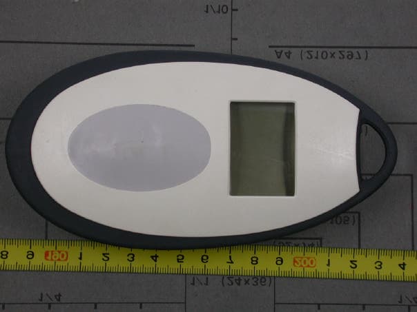
Click to zoom
Application Details
- Equipment Class
- DXT - Part 15 Low Power Transceiver, Rx Verified
- Date of Grant
- Feb 10, 2004
- Application Purpose
- Original Equipment
- Date of Application
- Feb 10, 2004
- Equipment Note
- Remote Control
- Frequency Range
- 903.14400000 - 903.14400000
- Company
- Bosch Termotecnologia S.A.
- Country
- Portugal
Documents & Files
Document Text
Text extracted from the exhibit documents filed with the FCC. Open a document above to read the original.
Users Manual
Bosch Remote Control for GWH-635-ES 6 720 606 990 JS 2 Contents 6 720 606 990 Contents 1Declaration of Conformity FCC 2 2 Remote Control Data 3 3 Parts supplied 3 4 Using the Remote Control 3 5 Maintenance 9 Safety Instructions BRead the following instructions very carefully to ensure perfect operation. BFollow safety instructions. 1 Declaration of Conformity FCC This device meets the requirements of FCC Directives and is compliant with the type-tested sample in the relative FCC test certificate. Caution: the remote control is waterproof and can also be used in the shower . Ne- vertheless, you should ensure it is not immersed in water, for instance in the bathtub . Caution: The remo- te control can be used only in the following countries: United States of America and Canada. 3 Remote Control Data 6 720 606 990 2 Remote Control Data Remote control for temperature adjustment of Bosch water heaters GWH-635-ES. Technical Data: Further Indications: 3 Parts supplied Fig. 1 Parts 1Remote control 2Remote control transceiver PCB 3Support 4PCB’s connection cable 4 Using the Remote Control 4.1 Description of the LCD Fig. 2 Multifunctional LCD 1Displays temperature, error codes and functions 2"Remote control in operation" indication (signal arriving at remote control) 3Device in operation (with burner on) 4Temperature measurement unit (possible in °C and °F) 5Remote control battery level indication (weak signal coming from the remote control) 6Priority function (temperature cannot be modified by other user interface when water is running) 7"Security lock" symbol Battery power supply Alkaline LR 6 2 x 1,5V Frequency915 MHz Type of protection IP X6 Remote control Up to 6 remote controls can be programmed for one single appliance.. 4 Using the Remote Control 6 720 606 990 4.2 Remote control trans- ceiver PCB installation Pre-installation preparation BRemove the plug from the supply socket. BRemove plastic decals on front panel. BUndo two Philips head screws located behind decals. BLift front cover panel upward and remove. BRemove the lower cover from the control box. BRemove the 2 sets of cables from the control box PCB. BUndo connections from both ignition cables. BRemove holding bracket. BRemove control box. Control box is now out of the appliance casing. Remote control transceiver PCB installation BOpen control box top cover (Fig. 3, pos. 1). BRemove the protective cover (Fig. 3, pos. 2) from one face of the support and fix it to the main PCB as shown in Fig. 3. Fig. 3 BRemove the other protective cover and fix the remote control PCB as shown in Fig. 4. Assure that the face of the remote control PCB is against the control box. Warning: For safety reasons, disconnect the power supply to the heater. 5 Using the Remote Control 6 720 606 990 Fig. 4 Support correct position BUsing the supplied cable make the connection between the main PCB and the remote control PCB as shown in Fig. 5. Fig. 5 BClose the control box cover. BRe-assemble: • the control box in the appliance • all connections between the PCB and the appliance • lower cover in the control box • holding bracket • front cover panel. 4.3 Remote Control Activa- tion BMove the main switch on the appliance to the 0 position. BPress and hold key while at the same time turn the main switch to “ON” position (I). LCD shows one number and one rotating digit. The number represents the remote control which is to be registered, the first remote control will be registered with number “0”, the second with number “1” and so on. i Before the remote control will work it will have to be activated, using the procedure described below, and standing in front of the appliance. 6 Using the Remote Control 6 720 606 990 The rotating digit shows that the electronics is expecting a registration. BHold remote control in front of the control panel on the heater and press simultaneously remote control buttons and until the temperature indication is shown on the remote control LCD. BSwitch ON/OFF switch to “OFF” position (0) and then back on (I). BPress buttons and in order to reach requested temperature. New remote control is programmed. 4.4 Hot Water Temperature Adjustment by Remote Control BPress the buttons or on the remote control (Fig. 6, pos. 2) until the required temperature appears on the remote control display (Fig. 6, pos. 1). BWhen the required temperature is defined, turn on the hot water tap. BThe required temperature will flash on the remote control display. BThe flashing will stop when the required temperature is reached (tolerance from selected set point -5 + 3 °K). Fig. 6 Temperature adjustment 4.5 "Program" Button on the Remote Control Memorizing the water temperature with the remote control "Program" button BPress the buttons or on the remote control (Fig. 7, pos. 2), ) until the required temperature appears on the remote control display (Fig. 7, pos. 1). BYou will now be able to memorize this temperature by keeping the "Program" button on the remote 7 Using the Remote Control 6 720 606 990 control (Fig. 7, pos. 3) pressed for 3 seconds. Fig. 7 Memorising water temperature BOnly one temperature can be memorized using the "Program" button on the remote control. BAt this point the remote control will display the memorized temperature . When the hot water tap is turned on, the water heater will supply hot water at the temperature memorized on the remote control. If the temperature was memorized using remote control buttons (it is possible to combine up to six remote controls), it can only be modified whilst hot water is flowing if the same remote control is used again (see chapter 4.6 "Priority Function"). Using the "Program" button (operation with memorized temperature) To operate the equipment with a previously memorized temperature: BPress the "Program" button on the remote control. The remote control display or control panel will now show the previously memorized temperature. When the hot water tap is turned on, the water heater will supply hot water afte…
Text truncated - open the document above for the full version.
Cover Letter(s)
Request for Confidentiality 03 February 2004 PHOENIX TEST-LAB GmbH Königswinkel 10 D32825 Blomberg Germany RE: Certification Application FCC ID: RTG8708300122 Please be advised that the following information is to be held confidential on behalf of Vulcano Termodomésticos S.A.: • Schematics • Block Diagram • Technical Description The application contains technical information which Vulcano Termodomésticos S.A deems to be trade secrets and proprietary. If made public, the information might be used to the disadvantage of the applicant in the market place. Thank you for your attention to this matter.
External Photos
FCC ID: RTG8708300122 External Photos FCC ID: RTG8708300122 External Photos
Internal Photos
FCC ID: RTG8708300122 Internal Photos FCC ID: RTG8708300122 Internal Photos FCC ID: RTG8708300122 Internal Photos
Test Report
EMV-PrüfzentrumEMI/EMC-Testcenter FCC-ID: Test Report No. 58002-30555-1 Page 1 of 17 Pages Straubing, 12 September 2003 T E S T - R E P O R T No. 58002-30555-1 for CELSIUS Remote Controller, Portable Unit Applicant: A. J. Fonseca Lda Test Specification: FCC Code of Federal Regulations, CFR 47, Part 15, Sections 15.209 and 15.249 Note: The test data of this report relate only to the individual item which has been tested. This report shall not be reproduced except in full extent without the written approval of the testing laboratory. EMV-PrüfzentrumEMI/EMC-Testcenter FCC-ID: Test Report No. 58002-30555-1 Page 2 of 17 Pages Table of Contents 1. Administrative Data....................................................................................3 2. Identification of Test Laboratory.................................................................4 3. Summary....................................................................................................5 4. Operation Mode and Configuration of EUT................................................6 5. Measuring Methods...................................................................................7 5.1. Field Strength of Emissions, Prescans in a fully-anechoic Room...................................................................................................7 5.2. Radiated Emission Measurement at Open Area Test Site..................9 6. Photographs Taken During Testing.........................................................10 7. List of Measurements...............................................................................13 8. Referenced Regulations..........................................................................16 Charts taken during testing...............................................................................17 EMV-PrüfzentrumEMI/EMC-Testcenter FCC-ID: Test Report No. 58002-30555-1 Page 3 of 17 Pages 1. Administrative Data Test item (EUT) Type designation CELSIUS Version of EUT: Serial number(s): MB Type of equipment: Remote Controller Parts/accessories: --- FCC-ID: Technical data Frequency range: 902 - 928 MHz Operational frequencies: --- Type of modulation: FM Pulse frequency: N/A Pulse width: N/A Class of emission: 140K0F3D Antenna: Integrated Power supply: 2 x 1.5 V Alakaline Batteries Applicant: (full address) A.J. Fonseca Lda Rua Herois de Mucaba, 32 4470-056 Gueifaes Portugal Contract identification: Verbal Contact person: Mr. Leal Duarte Manufacturer: Applicant Application details Receipt of EUT: 25 August 2003 Date of test: 01 September 2003 Note: EMV-PrüfzentrumEMI/EMC-Testcenter FCC-ID: Test Report No. 58002-30555-1 Page 4 of 17 Pages 2. Identification of Test Laboratory Details of the Test Laboratory Company name: Senton GmbH EMI/EMC Test Center Address: Aeussere Fruehlingstrasse 45 D-94315 Straubing Germany Laboratory Accreditation: DAR-Registration No. TTI-P-G 062/94-01 FCC Test Site registration number 90926 Industry Canada Test site registration: IC 3050 Name for contact purposes: Mr. Johann Roidt Phone: (+49) (0)9421 5522-0 Fax: (+49) (0)9421 5522-99 EMV-PrüfzentrumEMI/EMC-Testcenter FCC-ID: Test Report No. 58002-30555-1 Page 5 of 17 Pages 3. Summary Summary of test results The tested sample complies with the requirements set forth in the Code of Regulations CFR 47, Part 15, Sections 15.207, 15.209 and 15.249 of the Federal Communication Commission (FCC) and the Radio Standards Specification RSS-210 Issue 5, Section 7 (Category I Receiver) of Industry Canada (IC). Personnel involved in this report Laboratory Manager: Mr. Johann Roidt Responsible for testing: Mr. Johann Roidt Responsible for test report: Mr. Johann Roidt EMV-PrüfzentrumEMI/EMC-Testcenter FCC-ID: Test Report No. 58002-30555-1 Page 6 of 17 Pages 4. Operation Mode and Configuration of EUT Operation Mode 1) Continuous TX Configuration of EUT Not applicable List of ports and cables Port Description Classification 1 Cable type Cable length No ports List of devices connected to EUT Item Description Type Designation Serial no. or ID Manufacturer Not applicable 1 Ports shall be classified as ac power, dc power or signal/control port EMV-PrüfzentrumEMI/EMC-Testcenter FCC-ID: Test Report No. 58002-30555-1 Page 7 of 17 Pages 5. Measuring Methods 5.1. Field Strength of Emissions, Prescans in a fully-anechoic Room Rules and Specifications: Sections 15.109, 15.209, 15.245 Guide: ANSI C63.4 1997 Measurement Procedure: Radiated emissions are measured over the frequency range from 30 MHz to maximum frequency as specified in section 15.33. Measurements are made in both the horizontal and vertical planes of polarization in a fully anechoic room using a spectrum analyzer with the detector function set to peak and resolution as well as video bandwidth set to 100 kHz (below 1 GHz) or 1 MHz (above 1 GHz). All tests are performed at a test-distance of 3 meters. Hand-held or body-worn devices are rotated through three orthogonal axes to determine which attitude and configuration produces the highest emission relative to the limit and therefore shall be used for final testing. During the tests the EUT is rotated all around to find the maximum levels of emissions. The cables and equipment were placed and moved within the range of position likely to find their maximum emissions. EUT Fully anechoic chamber 3 m test distance Spectrum Analyzer EMV-PrüfzentrumEMI/EMC-Testcenter FCC-ID: Test Report No. 58002-30555-1 Page 8 of 17 Pages Test instruments used: No. Type Model Serial Number Manufacturer 01 Spectrum Analyzer FSP 30 100063 Rohde & Schwarz 02 Preamplifier CPA9231A 3393 Schaffner 03 Biconical antenna HK 116 829708/006 Rohde & Schwarz 04 Log. periodic antenna 3147 9112-1054 EMCO 05 Horn antenna 3115 9508-4553 EMCO 06 Horn antenna 3160-03 9112-1003 Emco 07 Horn antenna 3160-04 9112-1001 Emco 08 Horn antenna 3160-05 9112-1001 Emco 09 Horn antenna 3160-06 9112-1001 Emco 10 Horn antenna 3160-07 9112-1008 Emco 11 Horn antenna 3160-08 9112-1002 Emco 12 Horn…
Text truncated - open the document above for the full version.
Test Setup Photos
EMV-PrüfzentrumEMI/EMC-Testcenter FCC-ID: Test Report No. 58002-30555-1 Page 11 of 17 Pages Test setup for radiated emission measurement (fully anechoic room) EMV-PrüfzentrumEMI/EMC-Testcenter FCC-ID: Test Report No. 58002-30555-1 Page 12 of 17 Pages
Contact Information
Applicant
Pedro Abrantes(Product certification responsable)
Technical Contact
Senton GmbHJohann Roidt
[email protected]+49 9421 55 22 13
Aeussere Fruehlingstrasse 45 · Straubing · Germany
Non-Technical Contact
Senton GmbHJohann Roidt
[email protected]+49 9421 55 22 13
Test Firm
TUV SUD Product Service GmbH PS-EMC-STRRainer Heller
Technical Specifications
| # | Rule Parts | Frequency Range | Power Output |
|---|---|---|---|
| 1 | 15C | 903.144 MHz - 903.144 MHz | - |
Other Applications from Bosch Termotecnologia S.A.

RTG8708300283
Apr 28, 2009Remote Control Transceiver for Bosch Water Heater
Equipment Class
DXX - Part 15 Low Power Communication Device Transmitter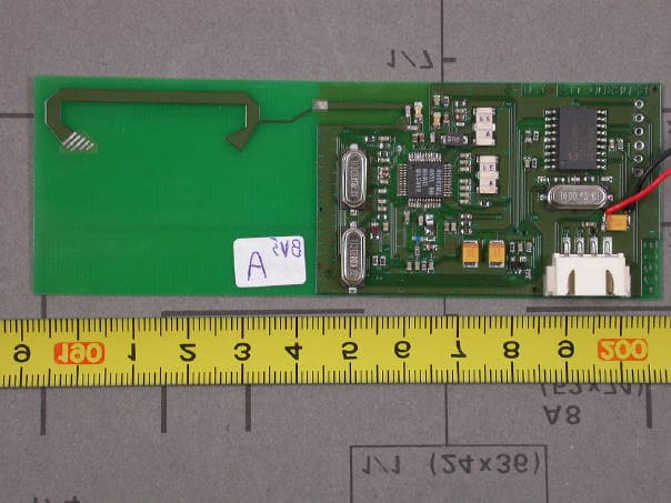
RTG8708300123
Feb 04, 2004Remote Control
Equipment Class
DXT - Part 15 Low Power Transceiver, Rx Verified